Page 1483 of 2643

5A1 – 134IZF 4 HP 16 AUTOMATIC TRANSAXLE
DAEWOO V–121 BL4
DIAGNOSTIC TROUBLE CODE(DTC) P1671
CAN TRANSMIT MESSAGE FAILURE
Circuit Description
The transaxle control module(TCM)is an electronic device
which monitors inputs to control various transaxle func-
tions including shift quality and transaxle sensors,
switches, and components to process for use within its’
control program. Based on this input information, the TCM
controls various transaxle output functions and devices.
Information is transmitted between the TCM and ECM
through the CAN. Information is as follows:
S Engine Malfunction Signal.
S Engine Speed.
S Engine Output Torque Reduction Signal.
S Engine Coolant Temperature.
Conditions for Setting the DTC
S System voltage is too high or too low.
S CAN transmitting wiring harness shortage or open.S TCM or ECM is defective.
S Immediately after the above condition occurs.
Action Taken When The DTC Sets
S The malfunction indicator lamp(MIL) will illuminate.
S The TCM will record operating conditions at the
time the diagnostic fails. This information will be
stored in the Failure Records buffer.
S Adopt Emergency/ Substitute mode and constant
4th gear by hydraulic control.
S After ignition OFF/ON : 3rd gear by hydraulic con-
trol. Possible P, R and N also possible.
Conditions for Clearing the MIL/DTC
S The MIL will turn OFF when the malfunction has
not occurred after three–ignition cycles.
S A history DTC will clear after 40 consecutive warm
up cycles without a fault.
S Using a scan tool can clear history DTCs.
Page 1485 of 2643

5A1 – 136IZF 4 HP 16 AUTOMATIC TRANSAXLE
DAEWOO V–121 BL4
DIAGNOSTIC TROUBLE CODE(DTC) P1672
CAN BUS OFF FAILURE
Circuit Description
The transaxle control module(TCM)is an electronic device
which monitors inputs to control various transaxle func-
tions including shift quality and transaxle sensors,
switches, and components to process for use within its’
control program. Based on this input information, the TCM
controls various transaxle output functions and devices.
Information is transmitted between the TCM and ECM
through the CAN. Information is as follows:
S Engine Malfunction Signal.
S Engine Speed.
S Engine Output Torque Reduction Signal.
S Engine Coolant Temperature.
Conditions for Setting the DTC
S System voltage is too high or too low.
S CAN transmitting wiring harness shortage or open.S TCM or ECM is defective.
S Immediately after the above condition occurs.
Action Taken When The DTC Sets
S The malfunction indicator lamp(MIL) will illuminate.
S The TCM will record operating conditions at the
time the diagnostic fails. This information will be
stored in the Failure Records buffer.
S Adopt Emergency/ Substitute mode and constant
4th gear by hydraulic control.
S After ignition OFF/ON : 3rd gear by hydraulic con-
trol. Possible P, R and N also possible.
Conditions for Clearing the MIL/DTC
S The MIL will turn OFF when the malfunction has
not occurred after three–ignition cycles.
S A history DTC will clear after 40 consecutive warm
up cycles without a fault.
S Using a scan tool can clear history DTCs.
Page 1487 of 2643

5A1 – 138IZF 4 HP 16 AUTOMATIC TRANSAXLE
DAEWOO V–121 BL4
DIAGNOSTIC TROUBLE CODE(DTC) P1673
CAN RECEIVE ECM MESSAGE FAILURE
Circuit Description
The transaxle control module(TCM) is an electronic de-
vice which monitors inputs to control various transaxle
functions including shift quality and transaxle sensors,
switches, and components to process for use within its’
control program. Based on this input information, the TCM
controls various transaxle output functions and devices.
Information is transmitted between the TCM and ECM
through the CAN. Information is as follows:
S Engine Malfunction Signal.
S Engine Speed.
S Engine Output Torque Reduction Signal.
S Engine Coolant Temperature.
Conditions for Setting the DTC
S System voltage is too high or too low.
S CAN transmitting wiring harness shortage or open.S TCM or ECM is defective.
S Immediately after the above condition occurs.
Action Taken When The DTC Sets
S The malfunction indicator lamp(MIL) will illuminate.
S The TCM will record operating conditions at the
time the diagnostic fails. This information will be
stored in the Failure Records buffer.
S Adopt Emergency/ Substitute mode and constant
4th gear by hydraulic control.
S After ignition OFF/ON : 3rd gear by hydraulic con-
trol. Possible P, R and N also possible.
Conditions for Clearing the MIL/DTC
S The MIL will turn OFF when the malfunction has
not occurred after three–ignition cycles.
S A history DTC will clear after 40 consecutive warm
up cycles without a fault.
S Using a scan tool can clear history DTCs.
Page 1552 of 2643
ZF 4 HP 16 AUTOMATIC TRANSAXLE 5A1 – 203
DAEWOO V–121 BL4
CONTROL VALVE BODY ASSEMBLY
Tools Required
DW260–070 Plug Remover/Installer
Removal Procedure
1. Disconnect the negative battery cable.
2. Disconnect the transaxle wiring harness and the
park/neutral position switch electrical connector.
3. Raise and suitably support the vehicle.
4. Remove the engine under cover. Refer to Section
9N, Frame and Underbody.
5. Remove the transaxle fluid drain plug using the
plug remover/installer DW260–070 and drain the
transaxle fluid.
6. Remove the oil pan, oil pan gasket. Refer to ”Oil
Pan, Oil Pan Gasket” in this section.
7. Remove the valve body mounting bolts.
8. Remove the automatic transmission input speed
sensor mounting bolt.
9. Remove the automatic transmission output speed
sensor mounting bolt.
Page 1553 of 2643
5A1 – 204IZF 4 HP 16 AUTOMATIC TRANSAXLE
DAEWOO V–121 BL4
10. Remove the control valve body.
Installation Procedure
1. Install the control valve body and the bolts.
Tighten
Tighten the valve body mounting bolts to 8 NSm (71
lb–in).
2. Install the input speed sensor mounting bolt.
Tighten
Tighten the input speed sensor mounting bolt to 8
NSm (71 lb–in).
3. Install the output speed sensor mounting bolt.
Tighten
Tighten the output speed sensor mounting bolt to 6
NSm (53 lb–in).
4. Install the oil pan and oil pan gasket. Refer to ”Oil
Pan Gasket” in this section.
5. Install the transaxle fluid drain plug using the plug
remove/installer DW260–070.
6. Install the engine under cover. Refer to Section 9N,
Frame and Underbody.
Page 1562 of 2643

ZF 4 HP 16 AUTOMATIC TRANSAXLE 5A1 – 213
DAEWOO V–121 BL4
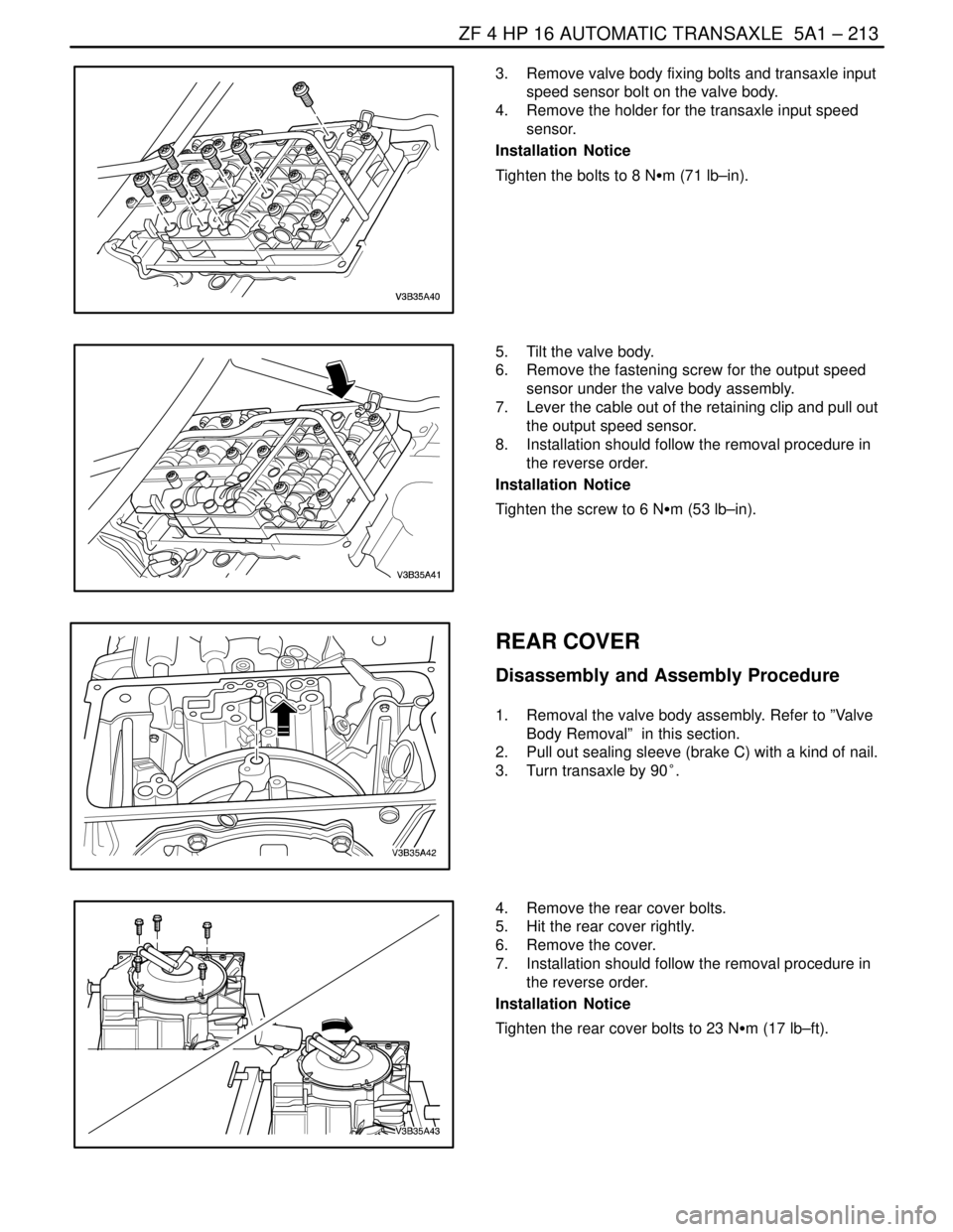
3. Remove valve body fixing bolts and transaxle input
speed sensor bolt on the valve body.
4. Remove the holder for the transaxle input speed
sensor.
Installation Notice
Tighten the bolts to 8 NSm (71 lb–in).
5. Tilt the valve body.
6. Remove the fastening screw for the output speed
sensor under the valve body assembly.
7. Lever the cable out of the retaining clip and pull out
the output speed sensor.
8. Installation should follow the removal procedure in
the reverse order.
Installation Notice
Tighten the screw to 6 NSm (53 lb–in).
REAR COVER
Disassembly and Assembly Procedure
1. Removal the valve body assembly. Refer to ”Valve
Body Removal” in this section.
2. Pull out sealing sleeve (brake C) with a kind of nail.
3. Turn transaxle by 90°.
4. Remove the rear cover bolts.
5. Hit the rear cover rightly.
6. Remove the cover.
7. Installation should follow the removal procedure in
the reverse order.
Installation Notice
Tighten the rear cover bolts to 23 NSm (17 lb–ft).
Page 1566 of 2643
ZF 4 HP 16 AUTOMATIC TRANSAXLE 5A1 – 217
DAEWOO V–121 BL4
17. Press down cup spring(clutch B)with cup spring
press fixture.
18. Remove the split stop ring.
19. Remove the cup spring.
20. Installation should follow the removal procedure in
the reverse order.
Adjustment Notice
Before assembling clutch B/E, setting discs(clutch B/E)
have to measured by below measurement procedure.
CLUTCH B/E MEASUREMENT
PROCEDURE
Tools Required
DW260–090 Clutch B/E(snap ring play, installation space)
Measuring Fixture
Determine Snap Ring Play
1. Put the dial gauge sensor on the clutch B adjusting
ring.
2. Feed compressed air to clutch B via control valves.
3. Set dial gauge to zero.
4. Pressurize clutch E via the control valve and read
measurement value.
5. Repeat measurement twice with disc set turned by
120°.
6. Average measurement values M1, M2, M3.(mea-
surement value is S)
S CALCULATION
S = (M1+M2+M3)/3
S EXAMPLE
– M1 = 0.27mm, M2 = 0.23mm, M3 = 0.25mm
– S = 0.25mm
Page 1567 of 2643

5A1 – 218IZF 4 HP 16 AUTOMATIC TRANSAXLE
DAEWOO V–121 BL4
Tools Required
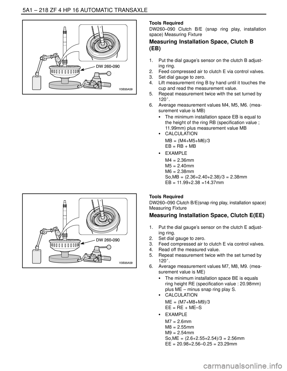
DW260–090 Clutch B/E (snap ring play, installation
space) Measuring Fixture
Measuring Installation Space, Clutch B
(EB)
1. Put the dial gauge’s sensor on the clutch B adjust-
ing ring.
2. Feed compressed air to clutch E via control valves.
3. Set dial gauge to zero.
4. Lift measurement ring B by hand until it touches the
cup and read the measurement value.
5. Repeat measurement twice with the set turned by
120°.
6. Average measurement values M4, M5, M6. (mea-
surement value is MB)
S The minimum installation space EB is equal to
the height of the ring RB (specification value ;
11.99mm) plus measurement value MB
S CALCULATION
MB = (M4+M5+M6)/3
EB = RB + MB
S EXAMPLE
M4 = 2.36mm
M5 = 2.40mm
M6 = 2.38mm
So,MB = (2.36+2.40+2.38)/3 = 2.38mm
EB = 11.99+2.38 =14.37mm
Tools Required
DW260–090 Clutch B/E(snap ring play, installation space)
Measuring Fixture
Measuring Installation Space, Clutch E(EE)
1. Put the dial gauge’s sensor on the clutch E adjust-
ing ring.
2. Set dial gauge to zero.
3. Feed compressed air to clutch E via control valves.
4. Read off the measured value.
5. Repeat measurement twice with the set turned by
120°.
6. Average measurement values M7, M8, M9. (mea-
surement value is ME)
S The minimum installation space BE is equals
ring height RE (specification value : 20.98mm)
plus ME – minus snap ring play S.
S CALCULATION
ME = (M7+M8+M9)/3
EE = RE + ME–S
S EXAMPLE
M7 = 2.6mm
M8 = 2.55mm
M9 = 2.54mm
So,ME = (2.6+2.55+2.54)/3 = 2.56mm
EE = 20.98+2.56–0.25 = 23.29mm