2004 DAEWOO LACETTI Lamp
[x] Cancel search: LampPage 1999 of 2643

HEATING AND VENTILATION SYSTEM 7A – 25
DAEWOO V–121 BL4
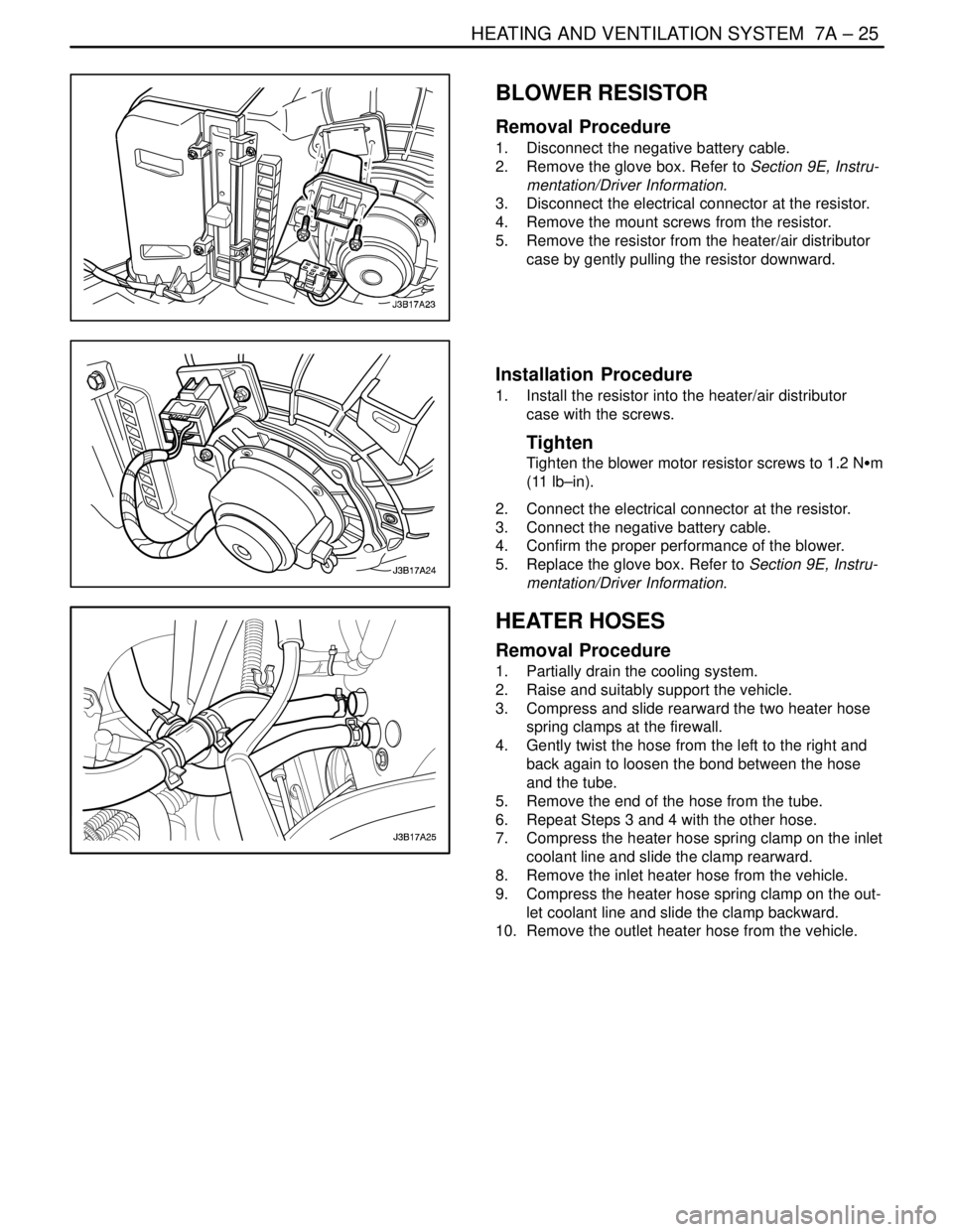
BLOWER RESISTOR
Removal Procedure
1. Disconnect the negative battery cable.
2. Remove the glove box. Refer to Section 9E, Instru-
mentation/Driver Information.
3. Disconnect the electrical connector at the resistor.
4. Remove the mount screws from the resistor.
5. Remove the resistor from the heater/air distributor
case by gently pulling the resistor downward.
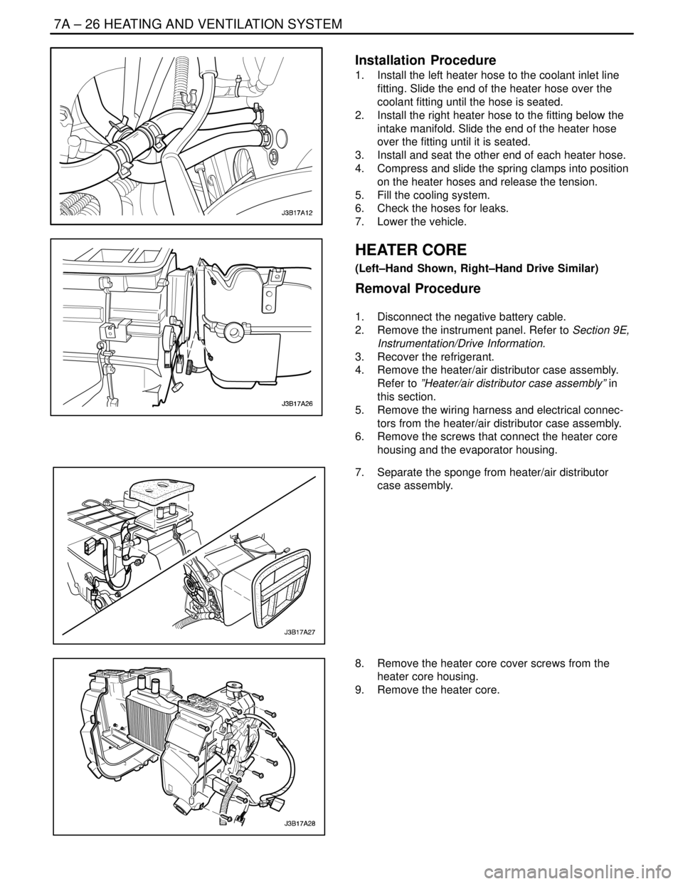
Installation Procedure
1. Install the resistor into the heater/air distributor
case with the screws.
Tighten
Tighten the blower motor resistor screws to 1.2 NSm
(11 lb–in).
2. Connect the electrical connector at the resistor.
3. Connect the negative battery cable.
4. Confirm the proper performance of the blower.
5. Replace the glove box. Refer to Section 9E, Instru-
mentation/Driver Information.
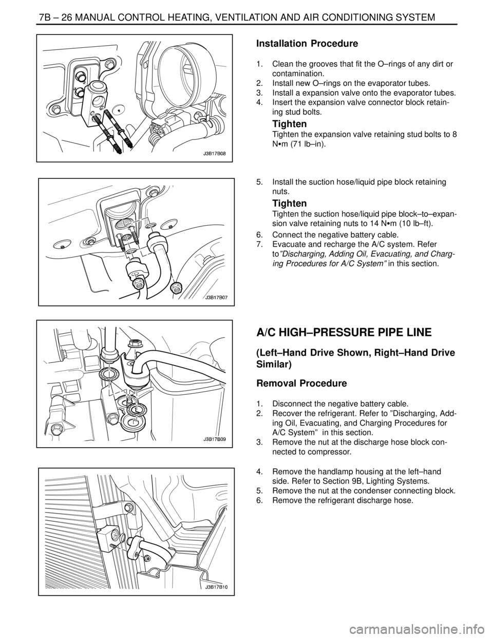
HEATER HOSES
Removal Procedure
1. Partially drain the cooling system.
2. Raise and suitably support the vehicle.
3. Compress and slide rearward the two heater hose
spring clamps at the firewall.
4. Gently twist the hose from the left to the right and
back again to loosen the bond between the hose
and the tube.
5. Remove the end of the hose from the tube.
6. Repeat Steps 3 and 4 with the other hose.
7. Compress the heater hose spring clamp on the inlet
coolant line and slide the clamp rearward.
8. Remove the inlet heater hose from the vehicle.
9. Compress the heater hose spring clamp on the out-
let coolant line and slide the clamp backward.
10. Remove the outlet heater hose from the vehicle.
Page 2000 of 2643

7A – 26IHEATING AND VENTILATION SYSTEM
DAEWOO V–121 BL4
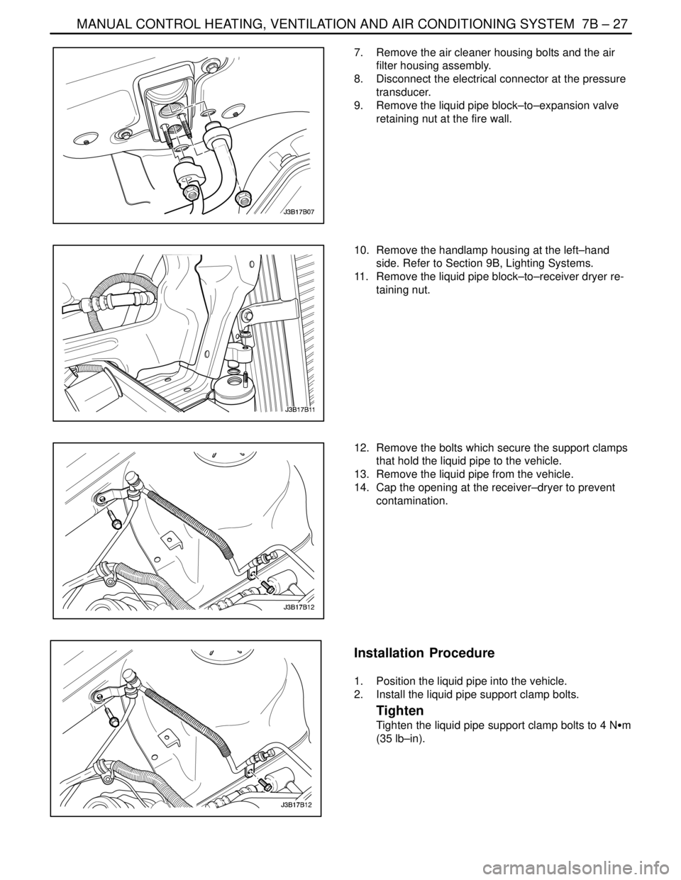
Installation Procedure
1. Install the left heater hose to the coolant inlet line
fitting. Slide the end of the heater hose over the
coolant fitting until the hose is seated.
2. Install the right heater hose to the fitting below the
intake manifold. Slide the end of the heater hose
over the fitting until it is seated.
3. Install and seat the other end of each heater hose.
4. Compress and slide the spring clamps into position
on the heater hoses and release the tension.
5. Fill the cooling system.
6. Check the hoses for leaks.
7. Lower the vehicle.
HEATER CORE
(Left–Hand Shown, Right–Hand Drive Similar)
Removal Procedure
1. Disconnect the negative battery cable.
2. Remove the instrument panel. Refer to Section 9E,
Instrumentation/Drive Information.
3. Recover the refrigerant.
4. Remove the heater/air distributor case assembly.
Refer to ”Heater/air distributor case assembly” in
this section.
5. Remove the wiring harness and electrical connec-
tors from the heater/air distributor case assembly.
6. Remove the screws that connect the heater core
housing and the evaporator housing.
7. Separate the sponge from heater/air distributor
case assembly.
8. Remove the heater core cover screws from the
heater core housing.
9. Remove the heater core.
Page 2002 of 2643

7A – 28IHEATING AND VENTILATION SYSTEM
DAEWOO V–121 BL4
GENERAL DESCRIPTION
AND SYSTEM OPERATION
HEATING AND VENTILATION
SYSTEMS
The base heater system is designed to provide heating,
ventilation, windshield defrosting, side window defogging,
and on some vehicles, heating directly to the rear seat
area.
The heater and fan assembly blower regulates the airflow
from the air inlet for further processing and distribution.
The heater core transfers the heat from the engine coolant
to the inlet air.
The temperature door regulates the amount of the air that
passes through the heater core. The temperature door
also controls the temperature of the air by controlling the
mix of the heated air and the ambient air.
The mode door regulates the flow and the distribution of
the processed air to the heater ducts and to the defroster
ducts.
This console–mounted heating and ventilation panel con-
tains the following:
The Rotary Temperature Control Knob
1. The Rotary Temperature Control Knob
S Actuates by cable.
S Raises the temperature of the air entering the
vehicle by rotation toward the right, or the red
portion of the knob.
2. The Rotary Blower Control Knob
S Turns ON to operate the blower motor at four
speeds.
S Turns OFF to stop the blower.
S Operates completely independently both from
the mode control that regulates the defroster
door and from the temperature control knob.S Changes the fan speed in any mode and at any
temperature setting.
3. The Rotary Mode Control Knob
S Actuates by cable.
S Regulates the air distribution between the wind-
shield, the instrument panel, and the floor vents.
Two Push Knobs
1. The Rear Window Defogger Push Knob
S Controls the rear window defogger.
S Turns ON the rear window defogger when the
push knob is pressed and the indicator lamp is
illuminated.
2. The A/C Push Knob (if the vehicle is equipped with
air conditioning)
S Controls the A/C.
S Turns the A/C ON when the push knob is down.
However, if the blower control knob is OFF, the
A/C system is OFF, regardless of the position of
the A/C knob.
Fresh Air Control Level Or Push Knob
1. The Fresh Air Control Level
S Operates by cable.
S Switches between recirculating passenger
compartment air and bringing outside air into the
passenger compartment.
S Draws in outside air when the lever is moved to
the right.
S Recirculates inside air when the lever is moved
to the left.
2. The Fresh Air Control Push Knob
S Operates by cable.
S Switches between recirculating passenger
compartment air and bringing outside air into the
passenger compartment.
S Draws in outside air when knob is off.
S Recirculates inside air when the knob is down
with the indicator lamp illuminated.
Page 2004 of 2643

7B – 2IMANUAL CONTROL HEATING, VENTILATION AND AIR CONDITIONING SYSTEM
DAEWOO V–121 BL4
SPECIFICATIONS
GENERAL SPECIFICATIONS
ApplicationUnitDescription
Compressor–V5
Receiver–Dryer–AL R/DRIER
RefrigerantType–R–134a System
Capacityg640±20 (RHD : 680±20)
Refrigerant Oil in A/C SystemType–Union Carbide 488 PAG OIL
Capacitycc (ml)220
Evaporator Capacity (Airflow rate 8.7 kg/min)Kcal/h6000±10%
FASTENER TIGHTENING SPECIFICATIONS
ApplicationNSmLb–FtLb–In
Pressure Transducer7–62
Expansion Valve Stud Bolts8–71
Liquid Pipe Support Clamp Bolts4–35
Liquid Pipe Block–to–Receiver Dryer Retaining Nut1410–
Liquid Pipe Block–to–Expansion Valve Retaining Nut1410–
Refrigerant Discharge Hose Block–to–Condenser Retaining Nut1612–
Refrigerant Discharge Hose Block–to–Compressor Retaining Nut3324–
Evaporator Core Cover Screws1.2–11
Heater Core Housing–to–Evaporator Housing Retaining Screws1.2–11
Suction Hose Block–to–Compressor Retaining Nut3324–
Suction Hose Support Clamp–to–Longitudinal Member Bolt8–71
Suction Hose Support Clamp–to–Engine Bracket Bolt (1.4D, 1.6D only)4–35
Suction Hose Support Clamp–to–Engine Bracket Bolt (1.8D, 2.0D only)1410–
Suction Hose Block–to–Expansion Valve Retaining Nut1410–
(Receiver Dryer) Band Clamp Bolt5–44
Receiver Dryer–to–Condenser Pipe Block Bolt5–44
Upper Compressor–to–Bracket Mounting Bolts (1.4D, 1.6D only)2518–
Lower Compressor–to–Bracket Mounting Bolts (1.4D, 1.6D only)4533–
Front Compressor–to–Bracket Mounting Bolts (1.8D, 2.0D only)3526–
Rear Compressor–to–Bracket Mounting Bolts (1.8D, 2.0D only)2015–
Condenser Mount Bolts4–35
(Compressor) Clutch Plate and Hub Assembly Retaining Nut1713–
(Compressor) Through Bolts10–89
Page 2014 of 2643

7B – 12IMANUAL CONTROL HEATING, VENTILATION AND AIR CONDITIONING SYSTEM
DAEWOO V–121 BL4
V5 SYSTEM AIR CONDITIONING DIAGNOSIS
INSUFFICIENT COOLING DIAGNOSIS
Test Description
The numbers below refer to steps on the diagnostic table.
13. See the Important below.
32. See the Important below.Important : Perform this test under garage conditions with
the air temperature at 21–32°C (70–90°F), and no sun
load. Follow this test carefully for accurate results.
Important : Perform this test exactly as described to ob-
tain accurate results.
Step
ActionValue(s)YesNo
1Record the customer’s complaint.
Can you verify the customer’s complaint?–Go to Step 2System OK
21. Check the A/C fuse.
2. Check the blower fan operation.
3. Check the engine cooling fan operation.
4. Check the A/C compressor belt.
5. Check the A/C condenser for restricted airflow.
6. Check the clutch coil connection.
7. Repair or replace any components as needed.
8. Check the discharge air temperature with the
A/C turned ON.
Is the discharge air temperature normal?At least 7°C
(12°F) below
ambient air
temperatureSystem OKGo to Step 3
31. Turn the ignition switch to LOCK.
2. Connect the high– and the low–pressure
gauges.
Are both pressures within the value specified?69–345 kPa
(10–50 psi)Go to Step 4Go to Step 5
41. Check the A/C system for leaks.
2. Repair any refrigerant leaks as needed.
3. Recover, evacuate, and recharge the A/C sys-
tem.
4. Observe the two pressure gauges.
Are both pressures above the value specified?345 kPa
(50 psi)Go to Step 7–
5Observe the two pressure gauges.
Are both pressures below the value specified?69 kPa
(10 psi)Go to Step 6Go to Step 7
61. Add 0.45 kg (1 pound) of refrigerant R–134a.
2. Check the A/C system for leaks.
3. Repair any refrigerant leaks, as needed.
4. Recover, evacuate, and recharge the A/C sys-
tem.
5. Observe the two pressure gauges.
Are both pressures above the value specified?345 kPa
(50 psi)Go to Step 7–
71. Start the engine and allow it to run at idle.
2. Set the A/C controls to the following positions:
S The A/C switch to the ON.
S The fresh air control switch to fresh air (in-
dicator lamp OFF).
S The blower motor to 4.
S The temperature to full cold.
Does the A/C compressor clutch engage?–Go to Step 8Go to Step 10
Page 2017 of 2643

MANUAL CONTROL HEATING, VENTILATION AND AIR CONDITIONING SYSTEM 7B – 15
DAEWOO V–121 BL4
StepNo Yes Value(s) Action
241. Start the engine.
2. Observe the low–side pressure gauge while
running the engine between 3,000 and 3,800
rpm.
Does the low–side pressure rise rapidly?–Go to Step 32Go to Step 25
251. Recover the A/C system refrigerant.
2. Replace the A/C compressor.
3. Evacuate and recharge the A/C system.
Is the compressor functioning normally?–Go to Step 13–
26Check the low–side pressure.
Is the low–side pressure within the specified value?172–241 kPa
(25–35 psi)Go to Step 27Go to Step 32
27Feel the high–side pipe leading up to the expansion
valve connecting block.
Is the pipe cold before the connecting block?–Go to Step 28Go to Step 29
281. Check for a restriction in the high–side pipe
before the expansion valve.
2. Repair or replace the high–side pipe.
Is the pipe performing normally?–Go to Step 13–
29Add the specified amount of refrigerant to the A/C
system.
Does the cooling performance improve?0.40 kg
(14 ounces)Go to Step 30Go to Step 31
301. Check the A/C system for leaks.
2. Repair any refrigerant leaks, as needed.
3. Evacuate and recharge the A/C system.
4. Check the A/C system for leaks.
Is the system free from leaks?–Go to Step 13–
311. Recover the refrigerant.
2. Check the expansion valve for obstructions.
3. Repair or replace the expansion valve, as re-
quired.
4. Evacuate and recharge the system.
5. Check the A/C system for leaks.
Is the system free from leaks?–Go to Step 13–
321. Run the engine for 5 minutes at 2,000 rpm.
2. Set the A/C controls to the following positions:
S The A/C switch to the ON position.
S The fresh air control switch to recirculate
(indicator lamp ON).
S The blower motor to 1.
S The temperature to full cold.
3. Close all of the vehicle’s windows and doors.
4. Open the vehicle hood.
Is the low–side pressure within the specified value?172–241 kPa
(25–35 psi)Go to Step 13Go to Step 33
331. Recover the A/C system refrigerant.
2. Replace the A/C compressor control valve.
3. Evacuate and recharge the A/C system.
4. Check the A/C system for leaks.
Is the system free from leaks?–Go to Step 13–
Page 2028 of 2643

7B – 26IMANUAL CONTROL HEATING, VENTILATION AND AIR CONDITIONING SYSTEM
DAEWOO V–121 BL4
Installation Procedure
1. Clean the grooves that fit the O–rings of any dirt or
contamination.
2. Install new O–rings on the evaporator tubes.
3. Install a expansion valve onto the evaporator tubes.
4. Insert the expansion valve connector block retain-
ing stud bolts.
Tighten
Tighten the expansion valve retaining stud bolts to 8
NSm (71 lb–in).
5. Install the suction hose/liquid pipe block retaining
nuts.
Tighten
Tighten the suction hose/liquid pipe block–to–expan-
sion valve retaining nuts to 14 NSm (10 lb–ft).
6. Connect the negative battery cable.
7. Evacuate and recharge the A/C system. Refer
to”Discharging, Adding Oil, Evacuating, and Charg-
ing Procedures for A/C System” in this section.
A/C HIGH–PRESSURE PIPE LINE
(Left–Hand Drive Shown, Right–Hand Drive
Similar)
Removal Procedure
1. Disconnect the negative battery cable.
2. Recover the refrigerant. Refer to ”Discharging, Add-
ing Oil, Evacuating, and Charging Procedures for
A/C System” in this section.
3. Remove the nut at the discharge hose block con-
nected to compressor.
4. Remove the handlamp housing at the left–hand
side. Refer to Section 9B, Lighting Systems.
5. Remove the nut at the condenser connecting block.
6. Remove the refrigerant discharge hose.
Page 2029 of 2643

MANUAL CONTROL HEATING, VENTILATION AND AIR CONDITIONING SYSTEM 7B – 27
DAEWOO V–121 BL4
7. Remove the air cleaner housing bolts and the air
filter housing assembly.
8. Disconnect the electrical connector at the pressure
transducer.
9. Remove the liquid pipe block–to–expansion valve
retaining nut at the fire wall.
10. Remove the handlamp housing at the left–hand
side. Refer to Section 9B, Lighting Systems.
11. Remove the liquid pipe block–to–receiver dryer re-
taining nut.
12. Remove the bolts which secure the support clamps
that hold the liquid pipe to the vehicle.
13. Remove the liquid pipe from the vehicle.
14. Cap the opening at the receiver–dryer to prevent
contamination.
Installation Procedure
1. Position the liquid pipe into the vehicle.
2. Install the liquid pipe support clamp bolts.
Tighten
Tighten the liquid pipe support clamp bolts to 4 NSm
(35 lb–in).