Page 1942 of 2643
POWER STEERING GEAR 6C – 25
DAEWOO V–121 BL4
5. Install the cylinder end dust boot retaining clamps
with the installer KM–J–22610.
6. Install the tie rod end boot retaining clamps.
7. Reposition the adjusting nut to the marks on the
inner tie rod and install the outer tie rod by twisting
it onto the inner tie rod.
8. Perform a front toe adjustment. Refer to Section
2B, Wheel Alignment.
9. Tighten the adjusting nut.
Tighten
Tighten the outer tie rod adjusting nut to 64 NSm (47
lb–ft).
10. Install the rack bearing assembly into the rack and
pinion steering assembly. Refer to ”Rack Bearing”
in this section.
11. Install the valve and pinion assembly into the rack
and pinion steering assembly. Refer to ”Valve and
Pinion” in this section.
12. Install the rack and pinion steering assembly into
the vehicle. Refer to ”Rack and Pinion Assembly”
in this section.
Page 1954 of 2643
POWER STEERING GEAR 6C – 37
DAEWOO V–121 BL4
[Vehicle Speed – Actuator Current Relation]
SOLENOID RESISTANCE
13 W
The control module is installed on the right side of the au-
dio and can be accessible after the glove box is removed.
It receives signals from the vehicle speed sensor and the
steering wheel rotation sensor and processes them to de-
cide proper fluid flow through the actuator.
It also has a self–diagnosis. If it detects any malfunction,
it starts default mode, which is basically actuator full open
for light steering effort.
TERMINALCOLORFUNCTION
1SBActuator Low
2VActuator High
3BWSteering Wheel Sensor Ground
4–Not used
5GrSteering Wheel Sensor 5V ref.
6GWVSS
7–Not Used
8PIGN ON
9BrWarning Lamp
10BWGround
11–Not Used
12–Not Used
13LDiagnosis
14SBSteering Wheel Sensor Signal
Page 1955 of 2643

SECTION : 6E
STEERING WHEEL AND COLUMN
CAUTION : Disconnect the negative battery cable before removing or installing any electrical unit or when a tool
or equipment could easily come in contact with exposed electrical terminals. Disconnecting this cable will help
prevent personal injury and damage to the vehicle. The ignition must also be in LOCK unless otherwise noted.
TABLE OF CONTENTS
SPECIFICATIONS6E–1 . . . . . . . . . . . . . . . . . . . . . . . . . .
Fastener Tightening Specifications 6E–1. . . . . . . . . . .
SPECIAL TOOLS6E–2 . . . . . . . . . . . . . . . . . . . . . . . . . . .
Special Tools Table 6E–2. . . . . . . . . . . . . . . . . . . . . . . .
DIAGNOSIS6E–2 . . . . . . . . . . . . . . . . . . . . . . . . . . . . . . . .
Steering Column Diagnosis 6E–2. . . . . . . . . . . . . . . . .
MAINTENANCE AND REPAIR6E–8 . . . . . . . . . . . . . . .
ON–VEHICLE SERVICE 6E–8. . . . . . . . . . . . . . . . . . . . .
Headlamp/Turn Signal Switch and Lever 6E–8. . . . . .
Wiper Switch and Lever 6E–9. . . . . . . . . . . . . . . . . . . . Steering Wheel Rotation Sensor 6E–10. . . . . . . . . . . .
Steering Wheel Without SIR 6E–11. . . . . . . . . . . . . . . .
Steering Wheel With SIR 6E–13. . . . . . . . . . . . . . . . . .
Ignition Lock Cylinder and Switch 6E–13. . . . . . . . . . .
Steering Column 6E–15. . . . . . . . . . . . . . . . . . . . . . . . . .
UNIT REPAIR 6E–19. . . . . . . . . . . . . . . . . . . . . . . . . . . . .
Tilt Steering Column 6E–19. . . . . . . . . . . . . . . . . . . . . .
GENERAL DESCRIPTION AND SYSTEM
OPERATION6E–20 . . . . . . . . . . . . . . . . . . . . . . . . . . . . .
Steering Wheel and Column 6E–20. . . . . . . . . . . . . . . .
Ignition Key Reminder 6E–20. . . . . . . . . . . . . . . . . . . . .
SPECIFICATIONS
FASTENER TIGHTENING SPECIFICATIONS
ApplicationNSmLb–FtLb–In
Ignition Switch Housing Shear Bolts11–97
Ignition Switch Retaining Screw2.5–22
Steering Column Jacket Assembly Front Bracket Bolts2216–
Steering Column Jacket Assembly Rear Bracket Nuts2216–
Steering Shaft Universal Joint Pinch Bolt2518–
Steering Wheel Horn Cap Screws4.5–40
Steering Wheel Nut3828–
Steering Wheel Rotation Sensor Retaining Screw2–18
Support Housing Screws1612–
Turn Signal Switch Housing Screws3–27
Upper and Lower Steering Column Cover Panel Screws2.5–22
Page 1962 of 2643
6E – 8ISTEERING WHEEL AND COLUMN
DAEWOO V–121 BL4
MAINTENANCE AND REPAIR
ON–VEHICLE SERVICE
HEADLAMP/TURN SIGNAL SWITCH
AND LEVER
(Left–Hand Drive Shown, Right–Hand Dirve
Similar)
Removal Procedure
1. Disconnect the negative battery cable.
2. Remove the upper and the lower steering column
cover panel screws.
3. Remove the upper and the lower steering column
cover panels.
4. Remove the turn signal switch by pushing the tabs
on the top and the bottom of the switch housing.
5. Disconnect the electrical connections from the turn
signal switch.
Installation Procedure
1. Connect the electrical connections to the turn signal
switch.
2. Install the turn signal switch by snapping it into the
switch housing.
Page 1985 of 2643

HEATING AND VENTILATION SYSTEM 7A – 11
DAEWOO V–121 BL4
StepNo Yes Value(s) Action
211. Disconnect the resistor block connector.
2. Connect one lead of a self–powered test light
to any single lead on the resistor block. Use
the other lead to probe each of the other two
terminals.
Does the test light illuminate on all terminals?–Go to Step 23Go to Step 22
22Replace the resistor block.
Is the repair complete?–System OK–
231. Turn the ignition to LOCK.
2. Disconnect the connector from the resistor
block.
3. Connect a jumper lead from the positive termi-
nal on the battery to any wire terminal in the
connector.
4. Use a 12–volt test light to check for voltage
from the corresponding wire on the blower
speed switch.
5. Repeat the same test on the other wires.
Does the lamp light on all three wires?–Go to Step 25Go to Step 24
24Replace the blower speed switch.
Is the repair complete?–System OK–
25Repair the open in the affected wire.
Is the repair complete?–System OK–
IMPROPER AIR DELIVERY OR NO MODE SHIFT
This procedure provides a test of all functions of the heater/defroster unit.
1. Warm up the vehicle.
2. Keep the engine running.
3. Perform the tests outlined in the table below and look for the results indicated.
CONTROL SETTINGS
CORRECT RESULTS
Mode
KnobTe m p
Contro
lBlower
Motor
SwitchBlower
SpeedPower
Vent
OutletFloor
OutletDefrost
OutletSide
Window
Outlet
VentColdOffOffNo
AirflowNo
AirflowNo
AirflowNo
Airflow
VentCold4HighAmbient
AirflowNo
AirflowNo
AirflowNo
Airflow
FloorCold to
Hot4HighNo
AirflowCold to Hot
AirflowMinimum
Cold to Hot
AirflowMinimum
Cold to Hot
Airflow
De-
frosterCold to
Hot4HighNo
AirflowMinimum
Cold to Hot
AirflowCold to Hot
AirflowMinimum
Cold to Hot
Airflow
If any of these settings does not produce the correct results, perform the following diagnostic procedure.
Page 1988 of 2643

7A – 14IHEATING AND VENTILATION SYSTEM
DAEWOO V–121 BL4
StepNo Yes Value(s) Action
71. Check the temperature door travel, the cable,
and the linkage.
2. Adjust to full cold.
3. Check for full hot.
Is the repair complete?–System OK–
8Adjust or repair the floor/defroster and/or the vent/
floor mode.
Is the repair complete?–System OK–
9In the vent position, is the problem objectionable
bleed?–Go to Step 10Go to Step 15
101. Check the system case for leaks.
2. Check the floor outlet attachment.
Are there problems?–Go to Step 11Go to Step 12
11Repair the system case or the floor outlet attach-
ment as required.
Is the repair complete?–System OKGo to Step 12
121. Turn the ignition switch OFF.
2. Turn the temperature control knob to full hot,
then rapidly to full cold.
Do you hear the door slam just before you reach the
end of the control travel?–Go to Step 13Go to Step 14
13Adjust the vent door to vent more.
Is the repair complete?–System OK–
141. Check the temperature door travel, the cables,
and the linkage.
2. Verify that the temperature door goes to full
cold.
3. Check the temperature door for full hot.
Is the temperature door travel correct?–System OK–
151. Set the fresh air/recirculating air control to
fresh air (indicator lamp off).
2. Set the temperature control to full cold.
3. Start the vehicle and allow the engine to warm
up.
4. Measure the air temperature at the blower in-
let, or cowl, and at the vent air outlet inside the
vehicle.
Is the outlet air more than 5°C (41°F) warmer than
the inlet air?–Go to Step 16System OK
161. Check for hot air leaks from the engine
compartment to the blower inlet.
2. Repair, as needed.
Is the repair complete?–System OK–
Page 1995 of 2643

HEATING AND VENTILATION SYSTEM 7A – 21
DAEWOO V–121 BL4
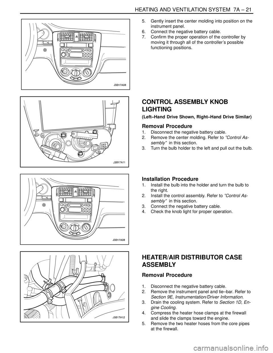
5. Gently insert the center molding into position on the
instrument panel.
6. Connect the negative battery cable.
7. Confirm the proper operation of the controller by
moving it through all of the controller’s possible
functioning positions.
CONTROL ASSEMBLY KNOB
LIGHTING
(Left–Hand Drive Shown, Right–Hand Drive Similar)
Removal Procedure
1. Disconnect the negative battery cable.
2. Remove the center molding. Refer to ”Control As-
sembly” in this section.
3. Turn the bulb holder to the left and pull out the bulb.
Installation Procedure
1. Install the bulb into the holder and turn the bulb to
the right.
2. Install the control assembly. Refer to ”Control As-
sembly” in this section.
3. Connect the negative battery cable.
4. Check the knob light for proper operation.
HEATER/AIR DISTRIBUTOR CASE
ASSEMBLY
Removal Procedure
1. Disconnect the negative battery cable.
2. Remove the instrument panel and tie–bar. Refer to
Section 9E, Instrumentation/Driver Information.
3. Drain the cooling system. Refer to Section 1D, En-
gine Cooling.
4. Compress the heater hose clamps at the firewall
and slide the clamps toward the engine.
5. Remove the two heater hoses from the core pipes
at the firewall.
Page 1997 of 2643

HEATING AND VENTILATION SYSTEM 7A – 23
DAEWOO V–121 BL4
Tighten
Tighten the heater/air distributor case assembly
screws to 4 NSm (35 lb–in).
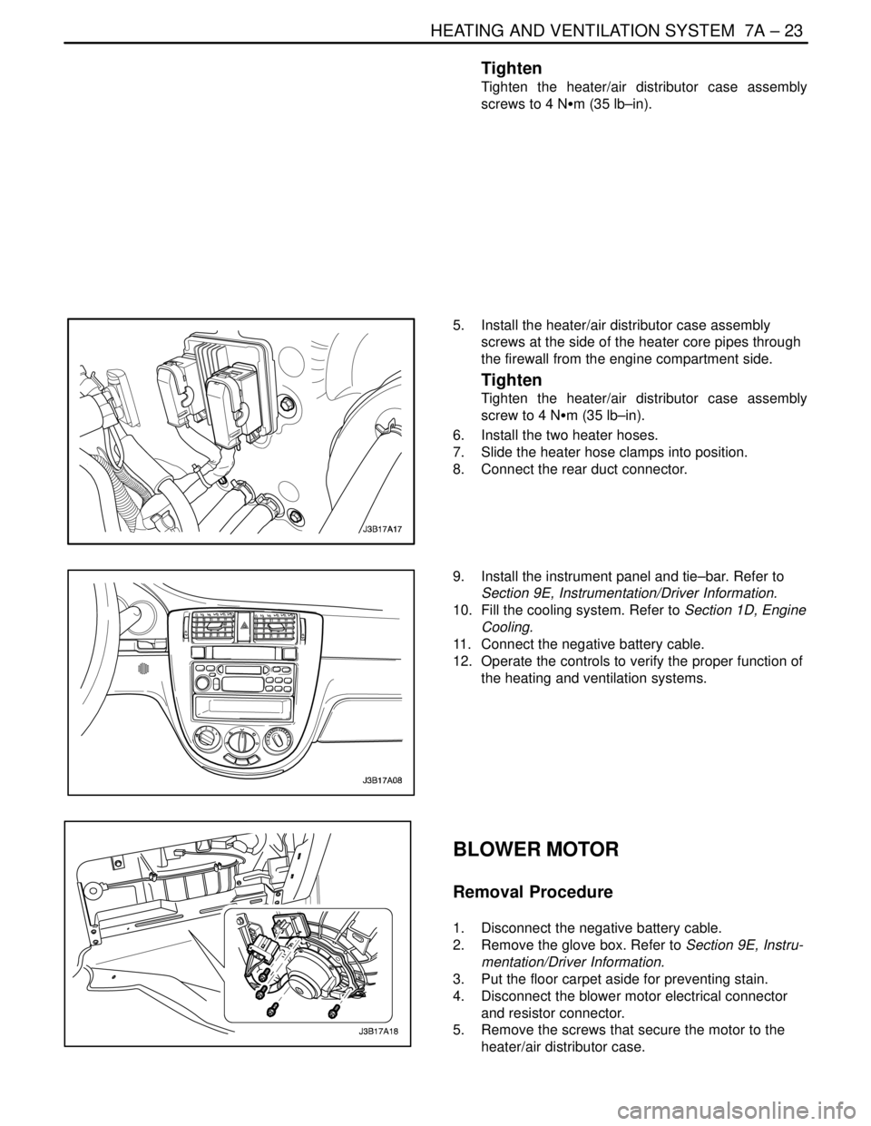
5. Install the heater/air distributor case assembly
screws at the side of the heater core pipes through
the firewall from the engine compartment side.
Tighten
Tighten the heater/air distributor case assembly
screw to 4 NSm (35 lb–in).
6. Install the two heater hoses.
7. Slide the heater hose clamps into position.
8. Connect the rear duct connector.
9. Install the instrument panel and tie–bar. Refer to
Section 9E, Instrumentation/Driver Information.
10. Fill the cooling system. Refer to Section 1D, Engine
Cooling.
11. Connect the negative battery cable.
12. Operate the controls to verify the proper function of
the heating and ventilation systems.
BLOWER MOTOR
Removal Procedure
1. Disconnect the negative battery cable.
2. Remove the glove box. Refer to Section 9E, Instru-
mentation/Driver Information.
3. Put the floor carpet aside for preventing stain.
4. Disconnect the blower motor electrical connector
and resistor connector.
5. Remove the screws that secure the motor to the
heater/air distributor case.