Page 2030 of 2643
7B – 28IMANUAL CONTROL HEATING, VENTILATION AND AIR CONDITIONING SYSTEM
DAEWOO V–121 BL4
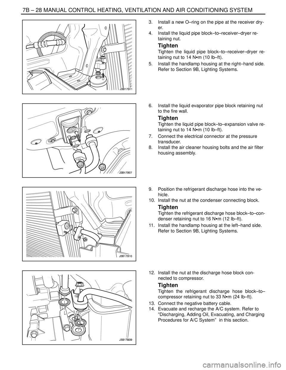
3. Install a new O–ring on the pipe at the receiver dry-
er.
4. Install the liquid pipe block–to–receiver–dryer re-
taining nut.
Tighten
Tighten the liquid pipe block–to–receiver–dryer re-
taining nut to 14 NSm (10 lb–ft).
5. Install the handlamp housing at the right–hand side.
Refer to Section 9B, Lighting Systems.
6. Install the liquid evaporator pipe block retaining nut
to the fire wall.
Tighten
Tighten the liquid pipe block–to–expansion valve re-
taining nut to 14 NSm (10 lb–ft).
7. Connect the electrical connector at the pressure
transducer.
8. Install the air cleaner housing bolts and the air filter
housing assembly.
9. Position the refrigerant discharge hose into the ve-
hicle.
10. Install the nut at the condenser connecting block.
Tighten
Tighten the refrigerant discharge hose block–to–con-
denser retaining nut to 16 NSm (12 lb–ft).
11. Install the handlamp housing at the left–hand side.
Refer to Section 9B, Lighting Systems.
12. Install the nut at the discharge hose block con-
nected to compressor.
Tighten
Tighten the refrigerant discharge hose block–to–
compressor retaining nut to 33 NSm (24 lb–ft).
13. Connect the negative battery cable.
14. Evacuate and recharge the A/C system. Refer to
”Discharging, Adding Oil, Evacuating, and Charging
Procedures for A/C System” in this section.
Page 2032 of 2643
7B – 30IMANUAL CONTROL HEATING, VENTILATION AND AIR CONDITIONING SYSTEM
DAEWOO V–121 BL4
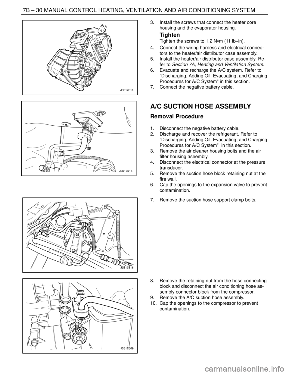
3. Install the screws that connect the heater core
housing and the evaporator housing.
Tighten
Tighten the screws to 1.2 NSm (11 lb–in).
4. Connect the wiring harness and electrical connec-
tors to the heater/air distributor case assembly.
5. Install the heater/air distributor case assembly. Re-
fer to Section 7A, Heating and Ventilation System.
6. Evacuate and recharge the A/C system. Refer to
”Discharging, Adding Oil, Evacuating, and Charging
Procedures for A/C System” in this section.
7. Connect the negative battery cable.
A/C SUCTION HOSE ASSEMBLY
Removal Procedure
1. Disconnect the negative battery cable.
2. Discharge and recover the refrigerant. Refer to
”Discharging, Adding Oil, Evacuating, and Charging
Procedures for A/C System” in this section.
3. Remove the air cleaner housing bolts and the air
filter housing aseembly.
4. Disconnect the elsctrical connector at the pressure
transducer.
5. Remove the suction hose block retaining nut at the
fire wall.
6. Cap the openings to the expansion valve to prevent
contamination.
7. Remove the suction hose support clamp bolts.
8. Remove the retaining nut from the hose connecting
block and disconnect the air conditioning hose as-
sembly connector block from the compressor.
9. Remove the A/C suction hose assembly.
10. Cap the openings to the compressor to prevent
contamination.
Page 2033 of 2643
MANUAL CONTROL HEATING, VENTILATION AND AIR CONDITIONING SYSTEM 7B – 31
DAEWOO V–121 BL4
Installation Procedure
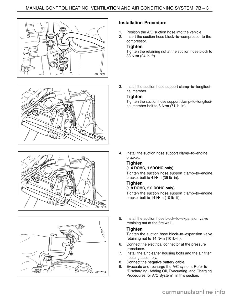
1. Position the A/C suction hose into the vehicle.
2. Insert the suction hose block–to–compressor to the
compressor.
Tighten
Tighten the retaining nut at the suction hose block to
33 NSm (24 lb–ft).
3. Install the suction hose support clamp–to–longitudi-
nal member.
Tighten
Tighten the suction hose support clamp–to–longitudi-
nal member bolt to 8 NSm (71 lb–in).
4. Install the suction hose support clamp–to–engine
bracket.
Tighten
(1.4 DOHC, 1.6DOHC only)
Tighten the suction hose support clamp–to–engine
bracket bolt to 4 NSm (35 lb–in).
Tighten
(1.8 DOHC, 2.0 DOHC only)
Tighten the suction hose support clamp–to–engine
bracket bolt to 14 NSm (10 lb–ft).
5. Install the suction hose block–to–expansion valve
retaining nut at the fire wall.
Tighten
Tighten the suction hose block–to–expansion valve
retaining nut to 14 NSm (10 lb–ft).
6. Connect the electrical connector at the pressure
transducer.
7. Install the air cleaner housing bolts and the air filter
housing assembly.
8. Connect the negative battery cable.
9. Evacuate and recharge the A/C system. Refer to
”Discharging, Adding Oil, Evacuating, and Charging
Procedures for A/C System” in this section.
Page 2034 of 2643
7B – 32IMANUAL CONTROL HEATING, VENTILATION AND AIR CONDITIONING SYSTEM
DAEWOO V–121 BL4
A/C DISCHARGE
HOSE–COMPRESSOR TO
CONDENSER
Removal Procedure
1. Disconnect the negative battery cable.
2. Recover the refrigerant. Refer to ”Discharging, Add-
ing Oil, Evacuating, and Charging Procedures for
A/C System” in this section.
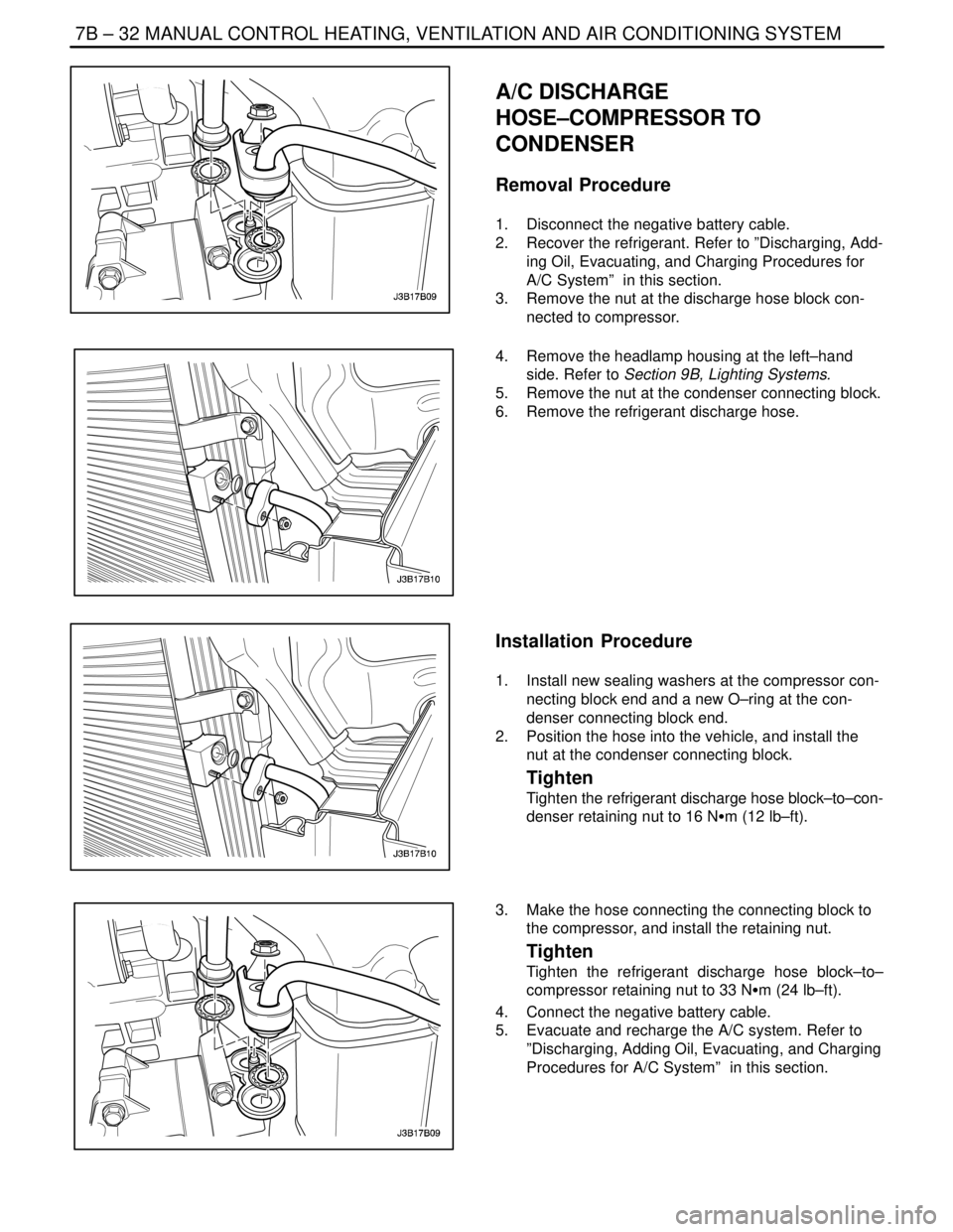
3. Remove the nut at the discharge hose block con-
nected to compressor.
4. Remove the headlamp housing at the left–hand
side. Refer to Section 9B, Lighting Systems.
5. Remove the nut at the condenser connecting block.
6. Remove the refrigerant discharge hose.
Installation Procedure
1. Install new sealing washers at the compressor con-
necting block end and a new O–ring at the con-
denser connecting block end.
2. Position the hose into the vehicle, and install the
nut at the condenser connecting block.
Tighten
Tighten the refrigerant discharge hose block–to–con-
denser retaining nut to 16 NSm (12 lb–ft).
3. Make the hose connecting the connecting block to
the compressor, and install the retaining nut.
Tighten
Tighten the refrigerant discharge hose block–to–
compressor retaining nut to 33 NSm (24 lb–ft).
4. Connect the negative battery cable.
5. Evacuate and recharge the A/C system. Refer to
”Discharging, Adding Oil, Evacuating, and Charging
Procedures for A/C System” in this section.
Page 2035 of 2643
MANUAL CONTROL HEATING, VENTILATION AND AIR CONDITIONING SYSTEM 7B – 33
DAEWOO V–121 BL4
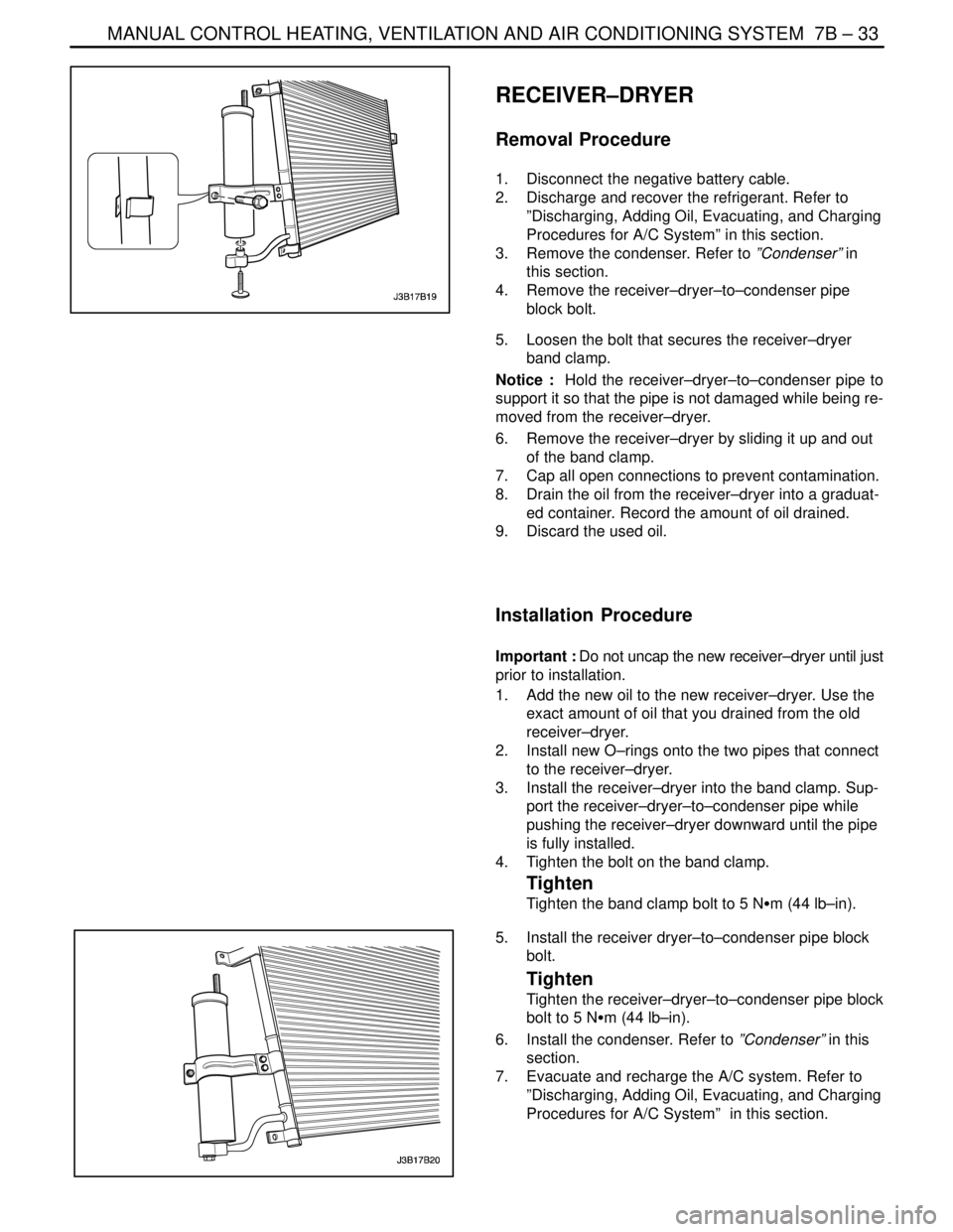
RECEIVER–DRYER
Removal Procedure
1. Disconnect the negative battery cable.
2. Discharge and recover the refrigerant. Refer to
”Discharging, Adding Oil, Evacuating, and Charging
Procedures for A/C System” in this section.
3. Remove the condenser. Refer to ”Condenser” in
this section.
4. Remove the receiver–dryer–to–condenser pipe
block bolt.
5. Loosen the bolt that secures the receiver–dryer
band clamp.
Notice : Hold the receiver–dryer–to–condenser pipe to
support it so that the pipe is not damaged while being re-
moved from the receiver–dryer.
6. Remove the receiver–dryer by sliding it up and out
of the band clamp.
7. Cap all open connections to prevent contamination.
8. Drain the oil from the receiver–dryer into a graduat-
ed container. Record the amount of oil drained.
9. Discard the used oil.
Installation Procedure
Important : Do not uncap the new receiver–dryer until just
prior to installation.
1. Add the new oil to the new receiver–dryer. Use the
exact amount of oil that you drained from the old
receiver–dryer.
2. Install new O–rings onto the two pipes that connect
to the receiver–dryer.
3. Install the receiver–dryer into the band clamp. Sup-
port the receiver–dryer–to–condenser pipe while
pushing the receiver–dryer downward until the pipe
is fully installed.
4. Tighten the bolt on the band clamp.
Tighten
Tighten the band clamp bolt to 5 NSm (44 lb–in).
5. Install the receiver dryer–to–condenser pipe block
bolt.
Tighten
Tighten the receiver–dryer–to–condenser pipe block
bolt to 5 NSm (44 lb–in).
6. Install the condenser. Refer to ”Condenser” in this
section.
7. Evacuate and recharge the A/C system. Refer to
”Discharging, Adding Oil, Evacuating, and Charging
Procedures for A/C System” in this section.
Page 2037 of 2643
MANUAL CONTROL HEATING, VENTILATION AND AIR CONDITIONING SYSTEM 7B – 35
DAEWOO V–121 BL4
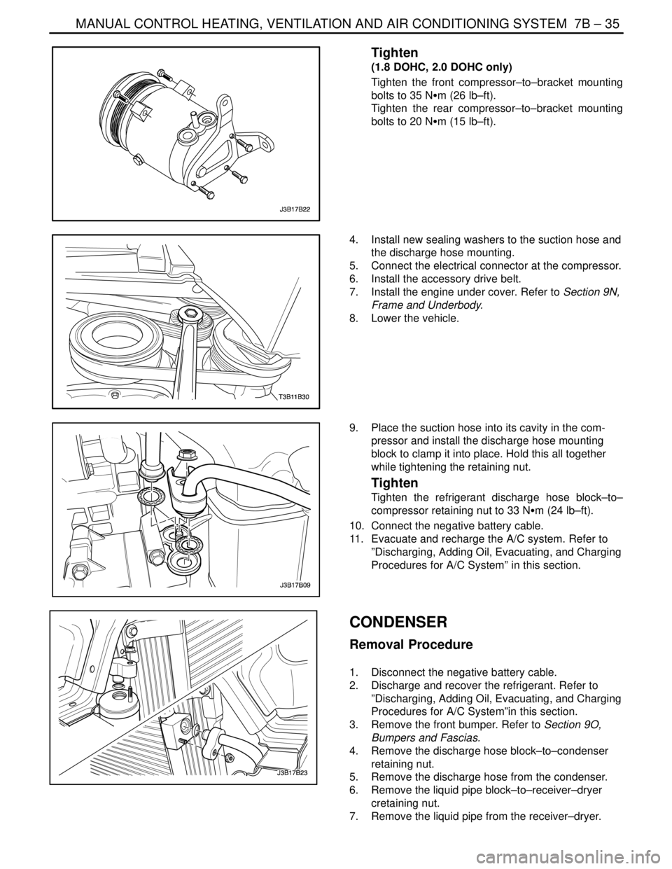
Tighten
(1.8 DOHC, 2.0 DOHC only)
Tighten the front compressor–to–bracket mounting
bolts to 35 NSm (26 lb–ft).
Tighten the rear compressor–to–bracket mounting
bolts to 20 NSm (15 lb–ft).
4. Install new sealing washers to the suction hose and
the discharge hose mounting.
5. Connect the electrical connector at the compressor.
6. Install the accessory drive belt.
7. Install the engine under cover. Refer to Section 9N,
Frame and Underbody.
8. Lower the vehicle.
9. Place the suction hose into its cavity in the com-
pressor and install the discharge hose mounting
block to clamp it into place. Hold this all together
while tightening the retaining nut.
Tighten
Tighten the refrigerant discharge hose block–to–
compressor retaining nut to 33 NSm (24 lb–ft).
10. Connect the negative battery cable.
11. Evacuate and recharge the A/C system. Refer to
”Discharging, Adding Oil, Evacuating, and Charging
Procedures for A/C System” in this section.
CONDENSER
Removal Procedure
1. Disconnect the negative battery cable.
2. Discharge and recover the refrigerant. Refer to
”Discharging, Adding Oil, Evacuating, and Charging
Procedures for A/C System”in this section.
3. Remove the front bumper. Refer to Section 9O,
Bumpers and Fascias.
4. Remove the discharge hose block–to–condenser
retaining nut.
5. Remove the discharge hose from the condenser.
6. Remove the liquid pipe block–to–receiver–dryer
cretaining nut.
7. Remove the liquid pipe from the receiver–dryer.
Page 2062 of 2643
AUTOMATIC TEMPERATURE CONTROL HEATING, VENTILATION, AND AIR CONDITIONING SYSTEM 7D – 7
DAEWOO V–121 BL4
CONTROLLER DOES NOT ILLUMINATE WHEN LIGHT
SWITCH IS ON
StepActionValue(s)YesNo
1Check other instrumentation lights.
Are those lights also off?–Go to Section
9E, Instrumen-
tation/Driver In-
formationGo to Step 2
21. Remove the controller.
2. Check the voltage between terminals A3 and
A4 of the controller connector.
Is the voltage within the specified value?11–14 vGo to Step 4Go to Step 3
3Repair the wiring harness between splice S204 and
controller connector terminal A4 or between splice
S203 and controller connector terminal A3.
Is the repair complete?–System OK–
4Check the illumination lamps.
Is one burned out?–Go to Step 5Go to Step 6
5Replace the burned out illumination lamp.
Is the repair complete?–System OK–
Page 2098 of 2643

SEAT BELTS 8A – 3
DAEWOO V–121 BL4
DIAGNOSIS
DRIVER SEAT BELT WARNING
Seat Belt Warning Lamp Does Not Turn On at Any Time
StepActionValue(s)YesNo
1Check the seat belt warning fuse F4.
Is fuse F4 blown?–Go to Step 2Go to Step 3
21. Check for a short circuit and repair if neces-
sary.
2. Replace the fuse.
Is the repair complete?–System OK–
31. Turn the ignition ON.
2. Check the voltage at fuse F4.
Is the voltage equal to the specified value?11–14 vGo to Step 5Go to Step 4
4Repair the open power supply circuit for fuse F4.
Is the repair complete?–System OK–
51. Disconnect the seat belt switch connector (lo-
cated under the driver’s seat).
2. Connect a jumper between the terminals on the
harness side of the seat belt switch connector.
3. Turn the ignition ON.
Does the seat belt warning lamp turn on?–Go to Step 6Go to Step 7
6Replace the seat belt switch.
Is the repair complete?–System OK–
71. Remove the instrument cluster.
2. Check the seat belt warning lamp bulb.
Is the bulb OK?–Go to Step 9Go to Step 8
8Replace the warning lamp bulb.
Is the repair complete?–System OK–
9Repair the open circuit between instrument cluster
terminal A11 and ground.
Is the repair complete?–System OK–