Page 1897 of 2643
5C – 10ICLUTCH
DAEWOO V–121 BL4
Installation Procedure
1. Coat the spline on the clutch disc with multi–pur-
pose grease.
2. Align the pressure plate and the clutch disc onto
the flywheel using the clutch arbor J–42474.
3. Install the pressure plate bolts.
Tighten
Tighten the bolts to 15 NSm (11 lb–ft).
4. Remove the clutch arbor J–42474.
5. Install the transaxle into the vehicle. Refer to Sec-
tion 5B, Five–Speed Manual Transaxle.
6. Connect the negative battery cable.
CLUTCH MASTER CYLINDER
ASSEMBLY
Removal Procedure
Before disconnecting the reservoir tank hose, remove the
clutch/brake fluid from the reservoir tank.
1. Remove the locking clip.
2. Remove the push rod fixing pin and push rod.
3. Disconnect the hose clamp on the master cylinder.
4. Disconnect the master cylinder hose.
5. Remove the master cylinder pipe.
Page 1898 of 2643
CLUTCH 5C – 11
DAEWOO V–121 BL4
6. Remove the clutch master cylinder nuts.
7. Remove the clutch master cylinder.
Installation Procedure
1. Install the clutch master cylinder and clutch master
cylinder nuts.
Tighten
Tighten the clutch master cylinder nuts to 22 NSm (16
lb–ft).
2. Install the master cylinder pipe.
3. Connect the master cylinder hose.
4. Connect the hose clamp on the master cylinder.
Page 1905 of 2643

6A – 4IPOWER STEERING SYSTEM
DAEWOO V–121 BL4
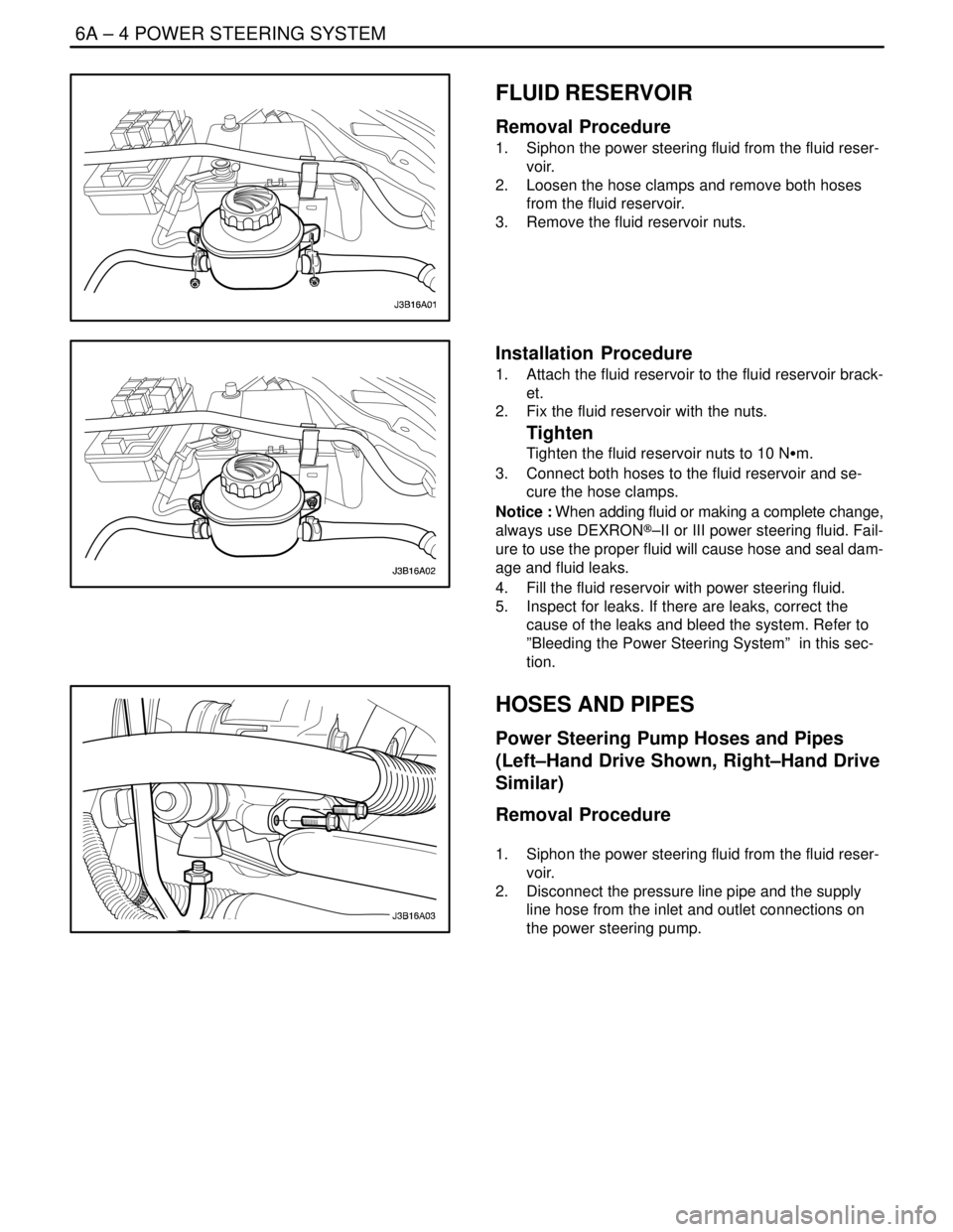
FLUID RESERVOIR
Removal Procedure
1. Siphon the power steering fluid from the fluid reser-
voir.
2. Loosen the hose clamps and remove both hoses
from the fluid reservoir.
3. Remove the fluid reservoir nuts.
Installation Procedure
1. Attach the fluid reservoir to the fluid reservoir brack-
et.
2. Fix the fluid reservoir with the nuts.
Tighten
Tighten the fluid reservoir nuts to 10 NSm.
3. Connect both hoses to the fluid reservoir and se-
cure the hose clamps.
Notice : When adding fluid or making a complete change,
always use DEXRON®–II or III power steering fluid. Fail-
ure to use the proper fluid will cause hose and seal dam-
age and fluid leaks.
4. Fill the fluid reservoir with power steering fluid.
5. Inspect for leaks. If there are leaks, correct the
cause of the leaks and bleed the system. Refer to
”Bleeding the Power Steering System” in this sec-
tion.
HOSES AND PIPES
Power Steering Pump Hoses and Pipes
(Left–Hand Drive Shown, Right–Hand Drive
Similar)
Removal Procedure
1. Siphon the power steering fluid from the fluid reser-
voir.
2. Disconnect the pressure line pipe and the supply
line hose from the inlet and outlet connections on
the power steering pump.
Page 1926 of 2643

POWER STEERING GEAR 6C – 9
DAEWOO V–121 BL4
StepNo Yes Value(s) Action
23Repair the open, short to ground, short to B+, or poor
terminal contact between terminal 14 of the SSPS
control module connector and terminal 2 of the
steering wheel rotation sensor connector.
Is the repair complete?–System OK–
241. Turn the ignition OFF.
2. Connect the SSPS control module.
3. Connect the steering wheel rotation sensor.
4. Turn the ignition ON.
5. Backprobe with a voltmeter from terminal 5 on
the control module connector to the ground.
6. Rotate the steering wheel quickly in both direc-
tions.
Does the voltage show an increase and decrease
from the specified value?� 3 VGo to Step 25Go to Step 26
25Replace the SSPS control module.
Is the repair complete?–System OK–
26Replace the steering wheel rotation sensor.
Is the repair complete?–System OK–
SPEED SENSITIVE POWER STEERING SYSTEM
OPERATING WITH DECREASED ASSIST AT ALL TIMES
StepActionValue(s)YesNo
1Check the speedometer.
Is speedometer inoperative?–Go to
Section5,
TransaxleGo to Step 2
2Disconnect the EVO solenoid actuator at the power
steering pump.
Is the symptom still present?–Go to
Section 6A,
Power Steering
SystemGo to Step 3
3Replace the speed sensitive poser steering (SSPS)
control module.
Is repair complete?–System OK–
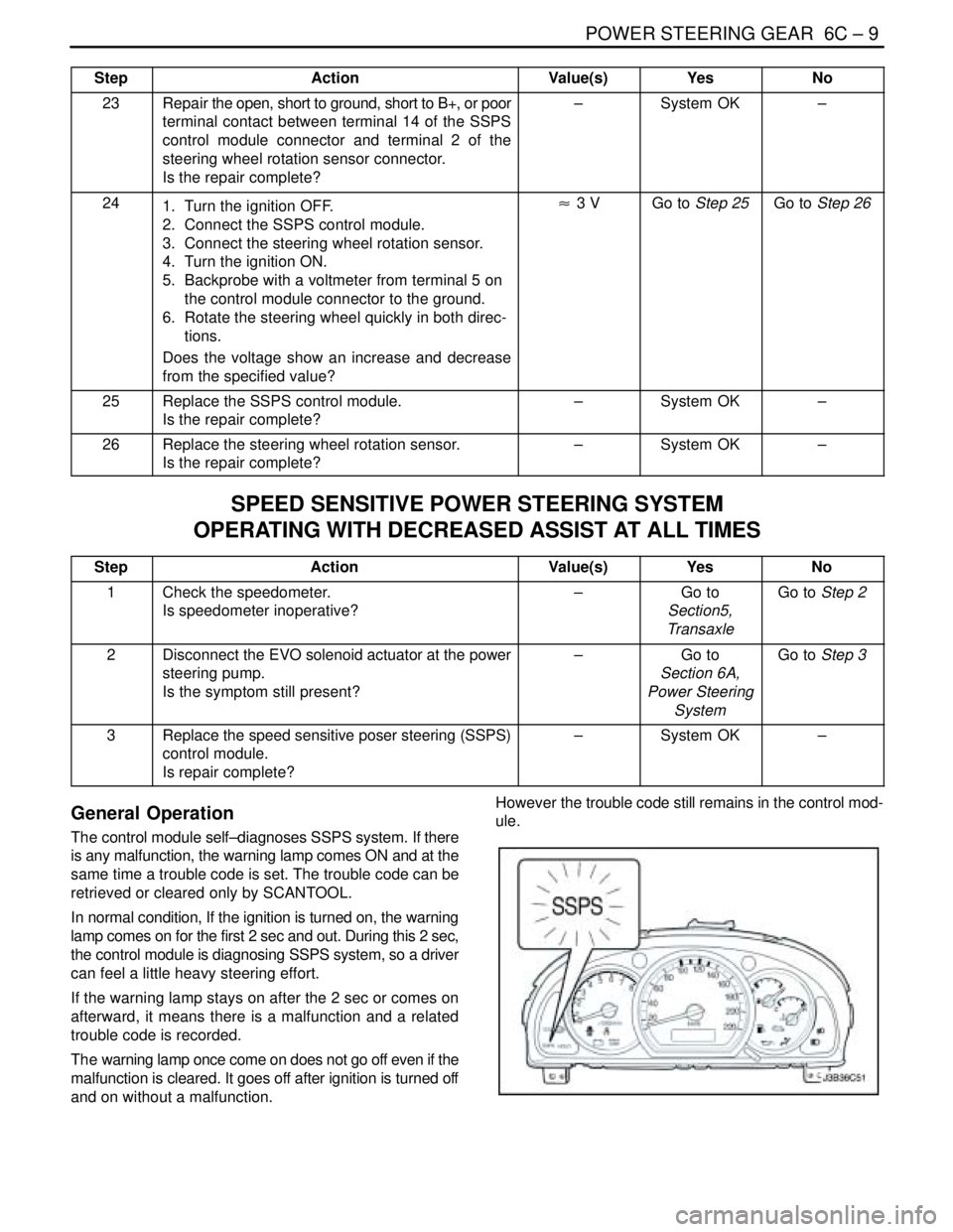
General Operation
The control module self–diagnoses SSPS system. If there
is any malfunction, the warning lamp comes ON and at the
same time a trouble code is set. The trouble code can be
retrieved or cleared only by SCANTOOL.
In normal condition, If the ignition is turned on, the warning
lamp comes on for the first 2 sec and out. During this 2 sec,
the control module is diagnosing SSPS system, so a driver
can feel a little heavy steering effort.
If the warning lamp stays on after the 2 sec or comes on
afterward, it means there is a malfunction and a related
trouble code is recorded.
The warning lamp once come on does not go off even if the
malfunction is cleared. It goes off after ignition is turned off
and on without a malfunction.However the trouble code still remains in the control mod-
ule.
Page 1927 of 2643
6C – 10IPOWER STEERING GEAR
DAEWOO V–121 BL4
Trouble Code
DTCTroubleDefault Action
01Actuator circuit open
02Actuator HI to LO short
03Actuator circuit short to B+
04Actuator HI short to GroundWarning lamp ON, Actuator Off
05Actuator LO short to Ground
06Steering Wheel Speed Sensor Open
07Steering Wheel Speed Sensor short to 5V
08Battey Voltage Out of Range (9~16 V)
Page 1932 of 2643

POWER STEERING GEAR 6C – 15
DAEWOO V–121 BL4
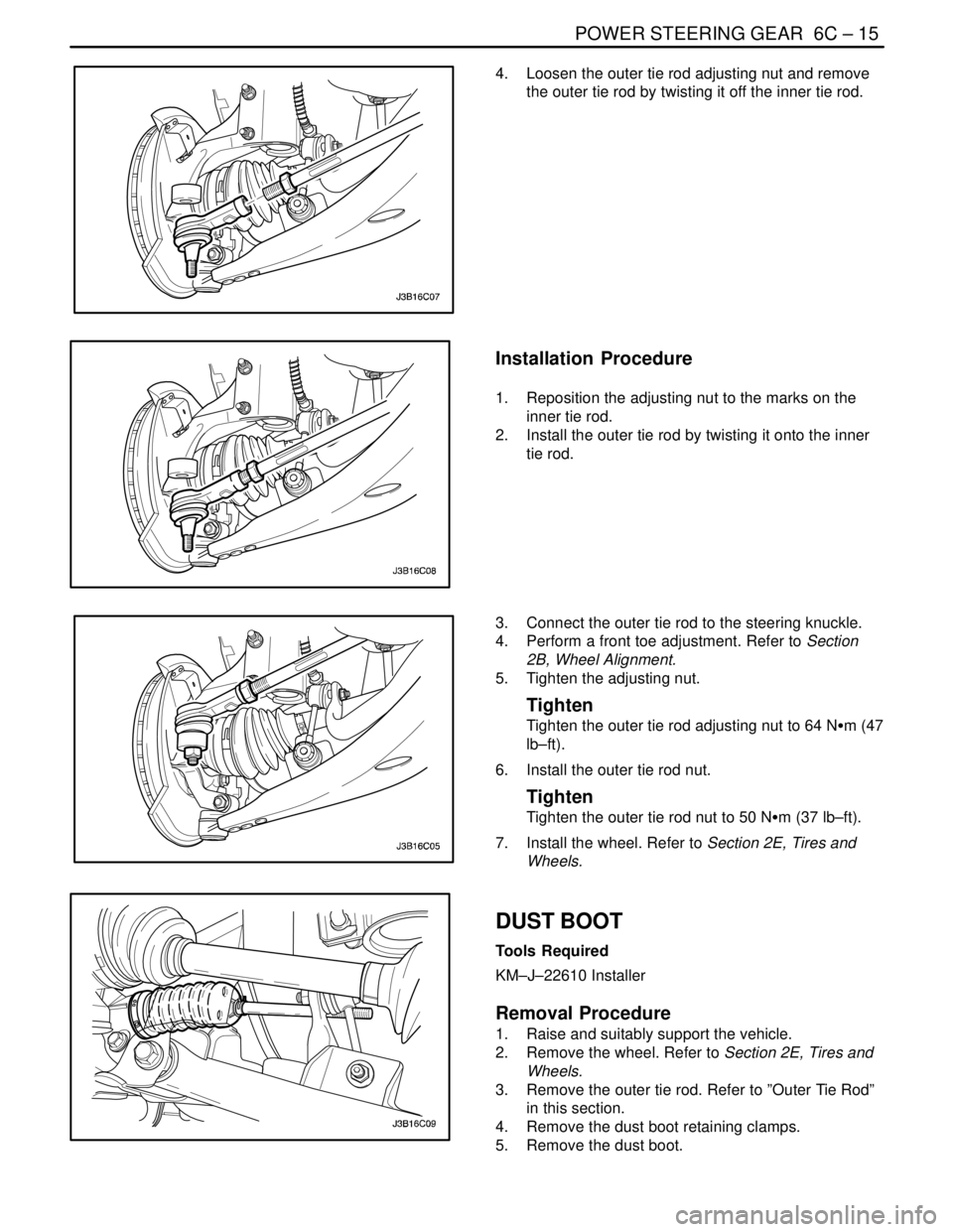
4. Loosen the outer tie rod adjusting nut and remove
the outer tie rod by twisting it off the inner tie rod.
Installation Procedure
1. Reposition the adjusting nut to the marks on the
inner tie rod.
2. Install the outer tie rod by twisting it onto the inner
tie rod.
3. Connect the outer tie rod to the steering knuckle.
4. Perform a front toe adjustment. Refer to Section
2B, Wheel Alignment.
5. Tighten the adjusting nut.
Tighten
Tighten the outer tie rod adjusting nut to 64 NSm (47
lb–ft).
6. Install the outer tie rod nut.
Tighten
Tighten the outer tie rod nut to 50 NSm (37 lb–ft).
7. Install the wheel. Refer to Section 2E, Tires and
Wheels.
DUST BOOT
Tools Required
KM–J–22610 Installer
Removal Procedure
1. Raise and suitably support the vehicle.
2. Remove the wheel. Refer to Section 2E, Tires and
Wheels.
3. Remove the outer tie rod. Refer to ”Outer Tie Rod”
in this section.
4. Remove the dust boot retaining clamps.
5. Remove the dust boot.
Page 1933 of 2643
6C – 16IPOWER STEERING GEAR
DAEWOO V–121 BL4
Installation Procedure
1. Install the dust boot.
2. Install the tie rod end dust boot retaining clamp.
Install the cylinder end dust boot retaining clamp
with the installer KM–J–22610.
3. Install the outer tie rod. Refer to ”Outer Tie Rod” in
this section.
4. Install the wheel. Refer to Section 2E, Tires and
Wheels.
5. Lower the vehicle.
STRAIGHT–AHEAD CHECK
After all the necessary operations on the steering gear are
completed (removing and installing, disassembling and
assembling), check the exact straight–ahead position of
the steering in each case.
With the vehicle on the floor, place the steering wheel in
the straight–ahead position. Mark the centerline of both
tires on the floor. Turn the steering wheel all the way to the
right and mark the new centerline of both tires on the floor.
Page 1939 of 2643
6C – 22IPOWER STEERING GEAR
DAEWOO V–121 BL4
UNIT REPAIR
RACK AND PINION
Tools Required
KM–J–22610 Installer
Disassembly Procedure
1. Remove the rack and pinion steering assembly
from the vehicle. Refer to ”Rack and Pinion Assem-
bly” in this section.
2. Remove the valve and pinion assembly from the
rack and pinion steering assembly. Refer to ”Valve
and Pinion” in this section.
3. Remove the rack bearing assembly from the rack
and pinion steering assembly. Refer to ”Rack Bear-
ing” in this section.
4. Mark the threads on the inner tie rod to aid in re-
positioning the adjusting nut.
5. Loosen the adjusting nut and remove the outer tie
rod nut and the adjusting nut.
6. Remove the dust boot retaining clamps.
7. Remove the dust boot.