Page 1702 of 2643
5A2 – 112IAISIN AUTOMATIC TRANSAXLE
DAEWOO V–121 BL4
7. Disconnect the input shaft speed (ISS) sensor elec-
trical connector.
8. Disconnect the output shaft speed (OSS) sensor
electrical connector.
9. Disconnect the Transmission Range (TR) Switch
electrical connector.
10. Disconnect the transaxle electrical connector.
11. Remove the service hall cover.
12. Remove the three torque converter bolts.
13. Remove the damping block connection nut and
bolt.
14. Remove the rear mounting bracket bolts and rear
mounting bracket.
15. Remove the three upper transaxle mounting brack-
et bolts.
Page 1705 of 2643
AISIN AUTOMATIC TRANSAXLE 5A2 – 115
DAEWOO V–121 BL4
5. Install the rear mounting bracket bolts and the
bracket.
Tighten
Tighten the rear mounting bracket bolts to 60 NSm (44
Ib–ft).
6. Install the damping block connection nut and bolt.
Tighten
Tighten the damping block connection nut and bolt to
80 NSm (59 Ib–ft).
7. Install the torque converter bolts.
Tighten
Tighten the torque converter bolts to 45 NSm (33 Ib–
ft).
8. Install the service hall cover.
9. Connect the transaxle electrical connector.
10. Connect the TR switch electrical connector.
11. Connect the OSS sensor electrical connector.
12. Connect the ISS sensor electrical connector.
13. Remove engine support fixture DW110–060.
14. Connect the shift control cable into the transaxle.
Refer to ”Shift Control Cable” in this section.
Page 1731 of 2643
AISIN AUTOMATIC TRANSAXLE 5A2 – 141
DAEWOO V–121 BL4
20. Install the differential gear to the transaxle case.
21. Install the transaxle housing and tighten the 16
bolts of the transaxle housing temporarily.
22. Tighten 8 or 9 bolts out of 16 bolts of the transaxle
housing completely.
Tighten
Tighten the bolt to 29 NSm (22 lb–ft).
23. Using differential preload adapter DW240–130, turn
the differential gear assembly right and left 2 or 3
times to allow the bearing settle.
24. Using differential preload adapter DW240–130 and
small torque wrench, measure the preload of the
differential gear.
Notice : Note down the measured valve.
Page 1732 of 2643
5A2 – 142IAISIN AUTOMATIC TRANSAXLE
DAEWOO V–121 BL4
25. Remove the transaxle housing and install the
counter driven gear.
26. Install the transaxle housing and tighten the 16
bolts of the transaxle housing temporarily.
27. Tighten the bolts of the transaxle housing in the
same manner as in step 22.
Tighten
Tighten the bolts to 29 NSm (22 lb–in).
28. Using differential preload adapter DW240–130, turn
the differential gear assembly right and left 2 or 3
times to allow the bearing settle.
29. Using differential preload adapter DW240–130 and
a small torque wrench, measure the preload of the
differential gear. From this valve deduct the valve
measured in step 23. This is the preload of the
counter driven gear.
S Preload:
New bearing: 0.33–0.76 NSm (3.21–6.77 lb–in)
Used bearing: 0.17–0.38 NSm (1.48–3.39 lb–in)
Page 1739 of 2643
AISIN AUTOMATIC TRANSAXLE 5A2 – 149
DAEWOO V–121 BL4
54. Using a small torque wrench, while turning to count-
er drive gear 100 turn per minute and measure the
preload.
Notice : When the preload is smaller than the specifica-
tion, tighten the nut more and adjust the preload. Preload:
0.05–0.35 NSm (0.43–3.12 lb–in)
Tighten
Tighten the nut to 29 NSm (22 lb–ft) or less.
55. Stake the nut.
56. Install the planetary gear to the transaxle case.
57. Coat the planetary carrier thrust washer with petro-
leum jelly and install it onto the planetary gear.
58. Install the No.2 one–way clutch to the transaxle
case.
Page 1756 of 2643
5A2 – 166IAISIN AUTOMATIC TRANSAXLE
DAEWOO V–121 BL4
138. Install the control lever, washer and nut.
Tighten
Tighten the nut to 12 NSm (106 lb–in).
139. Install the torque converter to the transaxle.
140. Measure the installation depth of the torque
converter. Standard value: 11.1 mm
If the measured value is beyond the standard
value, readjust the torque converter within the
specified value.
Page 1805 of 2643

AISIN AUTOMATIC TRANSAXLE 5A2 – 215
DAEWOO V–121 BL4
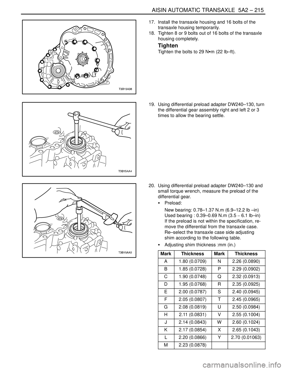
17. Install the transaxle housing and 16 bolts of the
transaxle housing temporarily.
18. Tighten 8 or 9 bolts out of 16 bolts of the transaxle
housing completely.
Tighten
Tighten the bolts to 29 NSm (22 lb–ft).
19. Using differential preload adapter DW240–130, turn
the differential gear assembly right and left 2 or 3
times to allow the bearing settle.
20. Using differential preload adapter DW240–130 and
small torque wrench, measure the preload of the
differential gear.
S Preload:
New bearing: 0.78–1.37 N.m (6.9–12.2 lb –in)
Used bearing : 0.39–0.69 N.m (3.5 � 6.1 lb–in)
If the preload is not within the specification, re-
move the differential from the transaxle case.
Re–select the transaxle case side adjusting
shim according to the following table.
S Adjusting shim thickness :mm (in.)
Mark
ThicknessMarkThickness
A1.80 (0.0709)N2.26 (0.0890)
B1.85 (0.0728)P2.29 (0.0902)
C1.90 (0.0748)Q2.32 (0.0913)
D1.95 (0.0768)R2.35 (0.0925)
E2.00 (0.0787)S2.40 (0.0945)
F2.05 (0.0807)T2.45 (0.0965)
G2.08 (0.0819)U2.50 (0.0984)
H2.11 (0.0831)V2.55 (0.1004)
J2.14 (0.0843)W2.60 (0.1024)
K2.17 (0.0854)X2.65 (0.1043)
L2.20 (0.0866)Y2.70 (0.01063)
M2.23 (0.0878)
Page 1808 of 2643

5A2 – 218IAISIN AUTOMATIC TRANSAXLE
DAEWOO V–121 BL4
GENERAL DESCRIPTION
AND SYSTEM OPERATION
TRANSAXLE DESCRIPTION
The new automatic transmission is an electronically con-
trolled 4–speed automatic transmission with Lock–up
mechanism.
The transmission is mainly composed of the torque con-
verter with lock up clutch, newly developed 4–speed plan-
etary gear unit, the hydraulic control system and the elec-
tric control system.
ELECTRONICAL COMPONENTS
Transmission Control Module (TCM)
The TCM primarily controls shift points and lockup en-
gagement. It is located on the driver side under the instru-
ment panel.
The transmission is controlled by an electronic shift sys-
tem. The Transmission Control Module (TCM) processes
input signals. From the information received, the TCM
controls the transmission hydraulic system.
The electronic shift system consists of the following :
S Transmission control module (TCM)
S Shift solenoids (SS1 and SS2)
S Pressure control solenoid (PCS)
S Lockup solenoid
S Input shaft speed (ISS) sensor
S Output shaft speed (OSS) sensor
S Transmission Fluid Temperature (TFT) sensor
S Transmission Range (TR) Switch
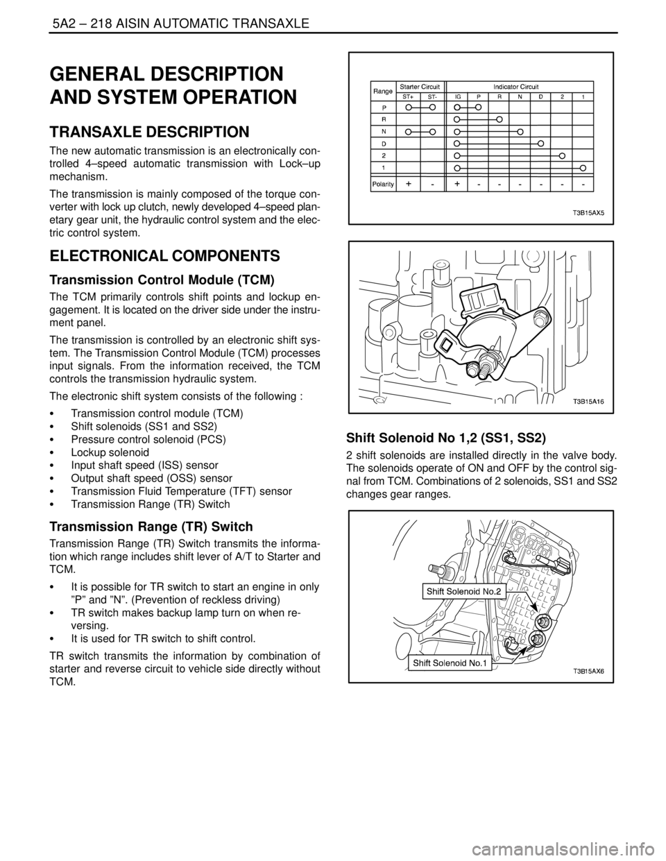
Transmission Range (TR) Switch
Transmission Range (TR) Switch transmits the informa-
tion which range includes shift lever of A/T to Starter and
TCM.
S It is possible for TR switch to start an engine in only
”P” and ”N”. (Prevention of reckless driving)
S TR switch makes backup lamp turn on when re-
versing.
S It is used for TR switch to shift control.
TR switch transmits the information by combination of
starter and reverse circuit to vehicle side directly without
TCM.
Shift Solenoid No 1,2 (SS1, SS2)
2 shift solenoids are installed directly in the valve body.
The solenoids operate of ON and OFF by the control sig-
nal from TCM. Combinations of 2 solenoids, SS1 and SS2
changes gear ranges.