2004 DAEWOO LACETTI torque
[x] Cancel search: torquePage 2021 of 2643

MANUAL CONTROL HEATING, VENTILATION AND AIR CONDITIONING SYSTEM 7B – 19
DAEWOO V–121 BL4
MAINTENANCE AND REPAIR
ON–VEHICLE SERVICE
GENERAL A/C SYSTEM SERVICE PROCEDURES
O–RING REPLACEMENT
Important : Even though O–rings may look identical, it is
extremely important that only recommended service re-
placement air conditioning O–rings be used or excessive
leakage of refrigerant may occur.
Important : Always slip the O–ring onto the flange tube to
ensure proper locating and sealing.
Install new Daewoo–approved service replacement air
conditioning (A/C) O–rings whenever a joint or a fitting is
disassembled, except when the O–rings are provided on
new components.
When replacing O–rings on an A/C component or a joint
connection, the fitting design should be identified to en-
sure installation of the correct air conditioning service re-
placement O–ring. Some joint connections and compo-
nents will implement a ”captured” O–ring design fitting that
uses a groove to retain the O–ring. Others do not have a
groove and use a ”non–captured” or ”standard” O–ring.
Assembly and tightening procedures are the same for
both designs, but the O–rings are different.
Notice : Before installation, verify that both O–rings and
fittings have not been nicked or deformed. Deformed or
nicked parts must be replaced. Failure to use the proper
service replacement parts and procedures may result in
excessive refrigerant leakage.
HANDLING REFRIGERANT
CAUTION : Always work in a well–ventilated area and
avoid breathing any refrigerant fumes. If you have dif-
ficulty with breathing, seek medical attention immedi-
ately. If refrigerant comes in contact with any part of
your body, flush the exposed area with water. If a rash
or pain develops, seek medical attention.
Air conditioning systems contain refrigerant. This is a
chemical mixture which requires special handling proce-
dures to avoid personal injury.
Always wear goggles and wrap a clean cloth around the
fittings, the valves and the connections when performing
work that involves opening the refrigerant system. Do not
weld or steam clean on or near any vehicle–installed air
conditioning lines or components.
All refrigerant drums are shipped with a heavy metal screw
cap. The purpose of the cap is to protect the valve and the
safety plug from damage. It is good practice to replace the
cap after each use of the drum.If it is necessary to transport or carry any container of re-
frigerant in a vehicle, do not carry it in the passenger
compartment.
HANDLING OF REFRIGERANT LINES
AND FITTINGS
Notice : Using too low or too high torque when tightening
a fitting can result in loose joints or deformed joint parts.
Both conditions can result in refrigerant leakage.
S Keep all metal tubing lines free of dents or kinks.
Any line restrictions will cause the loss of system
capacity.
S Never bend a flexible hose line to a radius of less
than four times the diameter of the hose.
S Never allow a flexible hose line to come within 65
mm (2–1/2 inches) of the exhaust manifold.
S Inspect flexible hose lines regularly for leaks or
brittleness.
S Replace flexible hose lines with new lines if you find
signs of deterioration or leaking.
S Discharge all refrigerant of the refrigeration system
before disconnecting any fitting in the refrigeration
system.
S Proceed very cautiously regardless of the gauge
readings.
CAUTION : Keep your face and your hands away from
the fitting so that you will not be injured if there hap-
pens to be liquid refrigerant in the line.
S Open the fittings very slowly.
S If you notice pressure when you loosen a fitting,
allow the pressure to bleed off as described under
”Discharging, Adding Oil, Evacuating, and Charging
Procedures for A/C System” in this section.
S Cap or tape any refrigerant line immediately after it
is opened. This will prevent the entrance of mois-
ture and dirt, which can cause internal compressor
wear or plugged lines in the condenser, the evapo-
rator core, the expansion valve, or the compressor
inlet screens.
Important : Use two proper wrenches to connect the O–
ring fittings.
S Back up the opposing fitting to prevent distortion of
the connecting lines or the components.
S Back up both the swagged fitting on the flexible
hose connections and the coupling to which it is
attached with two wrenches to prevent turning the
fitting and damaging the ground seat.
S Keep the O–rings and the seats in perfect condi-
tion. A burr or a piece of dirt may cause a refriger-
ant leak.
Page 2050 of 2643
7B – 48IMANUAL CONTROL HEATING, VENTILATION AND AIR CONDITIONING SYSTEM
DAEWOO V–121 BL4
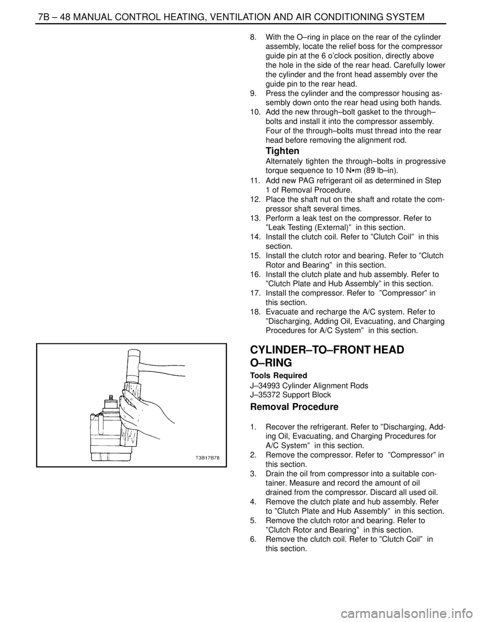
8. With the O–ring in place on the rear of the cylinder
assembly, locate the relief boss for the compressor
guide pin at the 6 o’clock position, directly above
the hole in the side of the rear head. Carefully lower
the cylinder and the front head assembly over the
guide pin to the rear head.
9. Press the cylinder and the compressor housing as-
sembly down onto the rear head using both hands.
10. Add the new through–bolt gasket to the through–
bolts and install it into the compressor assembly.
Four of the through–bolts must thread into the rear
head before removing the alignment rod.
Tighten
Alternately tighten the through–bolts in progressive
torque sequence to 10 NSm (89 lb–in).
11. Add new PAG refrigerant oil as determined in Step
1 of Removal Procedure.
12. Place the shaft nut on the shaft and rotate the com-
pressor shaft several times.
13. Perform a leak test on the compressor. Refer to
”Leak Testing (External)” in this section.
14. Install the clutch coil. Refer to ”Clutch Coil” in this
section.
15. Install the clutch rotor and bearing. Refer to ”Clutch
Rotor and Bearing” in this section.
16. Install the clutch plate and hub assembly. Refer to
”Clutch Plate and Hub Assembly” in this section.
17. Install the compressor. Refer to ”Compressor” in
this section.
18. Evacuate and recharge the A/C system. Refer to
”Discharging, Adding Oil, Evacuating, and Charging
Procedures for A/C System” in this section.
CYLINDER–TO–FRONT HEAD
O–RING
Tools Required
J–34993 Cylinder Alignment Rods
J–35372 Support Block
Removal Procedure
1. Recover the refrigerant. Refer to ”Discharging, Add-
ing Oil, Evacuating, and Charging Procedures for
A/C System” in this section.
2. Remove the compressor. Refer to ”Compressor” in
this section.
3. Drain the oil from compressor into a suitable con-
tainer. Measure and record the amount of oil
drained from the compressor. Discard all used oil.
4. Remove the clutch plate and hub assembly. Refer
to ”Clutch Plate and Hub Assembly” in this section.
5. Remove the clutch rotor and bearing. Refer to
”Clutch Rotor and Bearing” in this section.
6. Remove the clutch coil. Refer to ”Clutch Coil” in
this section.
Page 2051 of 2643
MANUAL CONTROL HEATING, VENTILATION AND AIR CONDITIONING SYSTEM 7B – 49
DAEWOO V–121 BL4
7. Remove and discard the shaft seal parts. Refer to
”Shaft Seal Replacement” in this section.
8. Remove the compressor through–bolts. Remove
and discard the gaskets.
9. Using a wooden block and a plastic–headed ham-
mer, tap the compressor housing at the mounting
locations to disengage the housing from the com-
pressor cylinder.
Important : Note the assembly sequence of the thrust
washer and bearing for ease of assembly.
10. Remove the thrust washer and the bearing.
11. Remove and discard the compressor housing–to–
cylinder O–ring.
Installation Procedure
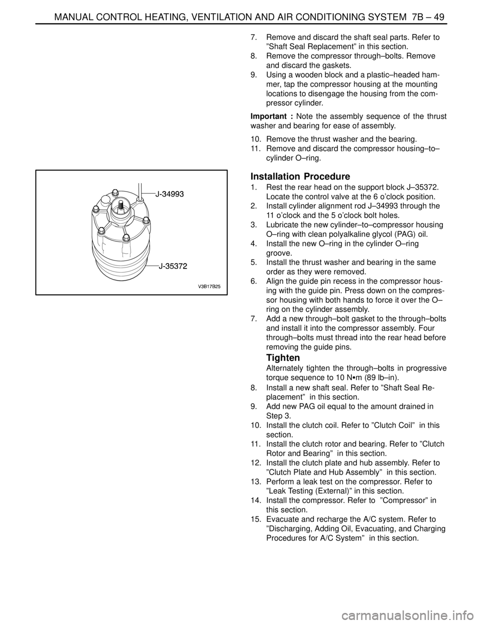
1. Rest the rear head on the support block J–35372.
Locate the control valve at the 6 o’clock position.
2. Install cylinder alignment rod J–34993 through the
11 o’clock and the 5 o’clock bolt holes.
3. Lubricate the new cylinder–to–compressor housing
O–ring with clean polyalkaline glycol (PAG) oil.
4. Install the new O–ring in the cylinder O–ring
groove.
5. Install the thrust washer and bearing in the same
order as they were removed.
6. Align the guide pin recess in the compressor hous-
ing with the guide pin. Press down on the compres-
sor housing with both hands to force it over the O–
ring on the cylinder assembly.
7. Add a new through–bolt gasket to the through–bolts
and install it into the compressor assembly. Four
through–bolts must thread into the rear head before
removing the guide pins.
Tighten
Alternately tighten the through–bolts in progressive
torque sequence to 10 NSm (89 lb–in).
8. Install a new shaft seal. Refer to ”Shaft Seal Re-
placement” in this section.
9. Add new PAG oil equal to the amount drained in
Step 3.
10. Install the clutch coil. Refer to ”Clutch Coil” in this
section.
11. Install the clutch rotor and bearing. Refer to ”Clutch
Rotor and Bearing” in this section.
12. Install the clutch plate and hub assembly. Refer to
”Clutch Plate and Hub Assembly” in this section.
13. Perform a leak test on the compressor. Refer to
”Leak Testing (External)” in this section.
14. Install the compressor. Refer to ”Compressor” in
this section.
15. Evacuate and recharge the A/C system. Refer to
”Discharging, Adding Oil, Evacuating, and Charging
Procedures for A/C System” in this section.
Page 2195 of 2643
SUPPLEMENTAL INFLATABLE RESTRAINTS (SIR) 8B – 91
DAEWOO V–121 BL4
Important : If the vehicle interior has been exposed to ex-
tensive water intrusion such as water leaks, driving
through high water, flooding or other causes, then the
SDM and SDM connector may need to be replaced. With
the ignition OFF, inspect the area of SDM, including the
carpet. If any significant soaking or evidence of previous
soaking is detected, the water must be removed, the water
damage repaired and the SDM and SDM connector must
be replaced. Before attempting any of these repairs, the
SRS must be disabled. Refer to ”Disabling the SIR” in this
section.
Removal and Installation Procedure
1. Disable the supplemental inflatable restraints(SIR).
Refer to ”Disabling the SIR” in this section.
2. Remove the floor console. Refer to section 9G, In-
terior Trim.
3. Remove the connector position assurance lock,
which is tethered to SDM connector.
4. Disconnect the SDM electrical connector.
5. Remove the SDM mounting bolts.
6. Remove the SDM.
7. Install the removed parts in the reverse order.
Installation Notice
Tightening torque of SDM mounting bolts is 10 NSm
(89 lb–in).
Enable the SIR. Refer to”Enabling the SIR”
in this section.
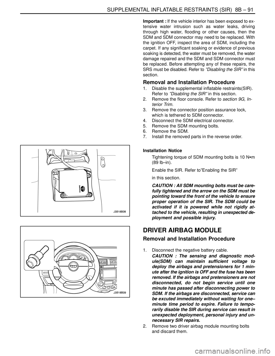
CAUTION : All SDM mounting bolts must be care-
fully tightened and the arrow on the SDM must be
pointing toward the front of the vehicle to ensure
proper operation of the SIR. The SDM could be
activated if it is powered while not rigidly at-
tached to the vehicle, resulting in unexpected de-
ployment and possible injury.
0
DRIVER AIRBAG MODULE
Removal and Installation Procedure
1. Disconnect the negative battery cable.
CAUTION : The sensing and diagnostic mod-
ule(SDM) can maintain sufficient voltage to
deploy the airbags and pretensioners for 1 min-
ute after the ignition is OFF and the fuse has been
removed. If the airbags and pretensioners are not
disconnected, do not begin service until one
minute has passed after disconnecting power to
SDM. If the airbags are disconnected, service can
be excuted immediately without waiting for one–
minute time period to expire. Failure to tempo-
rarily disable the SIR during service can result in
unexpected deployment, personal injury and un-
necessary SIR repairs.
2. Remove two driver airbag module mounting bolts
and discard them.
Page 2196 of 2643

8B – 92ISUPPLEMENTAL INFLATABLE RESTRAINTS (SIR)
DAEWOO V–121 BL4
3. Remove the connector from the driver airbag mod-
ule.
4. Remove the driver airbag module.
CAUTION : When handling an airbag module, al-
ways keep the top the unit facing upward. This
leaves room for the airbag to expand if the mod-
ule unexpectedly deploys. Without room for ex-
pansion, a module suddenly propelled toward a
person or object can cause injury or vehicle dam-
age.
5. Installation should follow the removal procedure in
the reverse order.
Installation Notice
Tightening torque of the driver airbag module mount-
ing bolt is 8 NSm (71 lb–in).
CLOCK SPRING
Removal and Installation Procedure
CAUTION : The sensing and diagnostic mod-
ule(SDM) can maintain sufficient voltage to
deploy the airbags and pretensioners for 1 min-
ute after the ignition is OFF and the fuse has been
removed. If the airbags and pretensioners are not
disconnected, do not begin service until one
minute has passed after disconnecting power to
SDM. If the airbags are disconnected, service can
be excuted immediately without waiting for one–
minute time period to expire. Failure to tempo-
rarily disable the SIR during service can result in
unexpected deployment, personal injury and un-
necessary SIR repairs.
1. Disconnect the negative battery cable.
2. Remove the driver airbag module. Refer to ”Driver
airbag module” in this section.
3. Remove the steering wheel. Refer to Section 6E,
Steering Wheel and Column.
4. Remove the screws from the upper and lower
steering column covers. And remove the covers.
Page 2197 of 2643
SUPPLEMENTAL INFLATABLE RESTRAINTS (SIR) 8B – 93
DAEWOO V–121 BL4
5. Remove the driver side knee bolster or instrument
panel lower cover.
6. Disconnect the driver airbag, horn and connectors
from the lower steering column.
7. Remove the screws and discard them.
8. Remove the clock spring from the steering shaft.
9. Installation should follow the removal procedure in
the reverse order. Refer to ”Clock Spring Align-
ment” in this section for alignment.
Tightening torque of the clock spring screw is 3 NSm
(27 lb–in).
CAUTION : If the clock spring is not properly
aligned, the steering wheel may not be able to ro-
tate completely during a turn. Restricted turning
ability can cause the vehicle to crash. Improper
alignment of the clock spring also may make the
SIR inoperative, preventing the airbag from de-
ploying during crash. Both of the out comes can
result in injury.
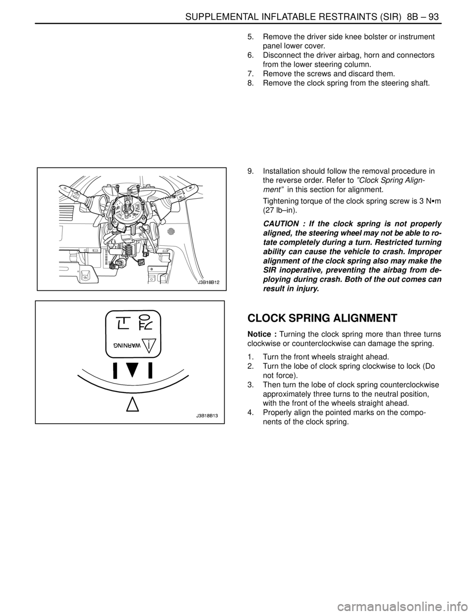
CLOCK SPRING ALIGNMENT
Notice : Turning the clock spring more than three turns
clockwise or counterclockwise can damage the spring.
1. Turn the front wheels straight ahead.
2. Turn the lobe of clock spring clockwise to lock (Do
not force).
3. Then turn the lobe of clock spring counterclockwise
approximately three turns to the neutral position,
with the front of the wheels straight ahead.
4. Properly align the pointed marks on the compo-
nents of the clock spring.
Page 2198 of 2643
8B – 94ISUPPLEMENTAL INFLATABLE RESTRAINTS (SIR)
DAEWOO V–121 BL4
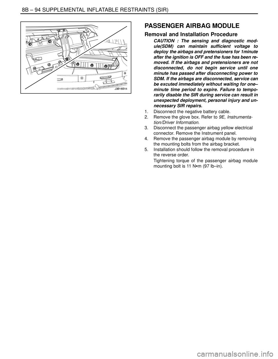
PASSENGER AIRBAG MODULE
Removal and Installation Procedure
CAUTION : The sensing and diagnostic mod-
ule(SDM) can maintain sufficient voltage to
deploy the airbags and pretensioners for 1minute
after the ignition is OFF and the fuse has been re-
moved. If the airbags and pretensioners are not
disconnected, do not begin service until one
minute has passed after disconnecting power to
SDM. If the airbags are disconnected, service can
be excuted immediately without waiting for one–
minute time period to expire. Failure to tempo-
rarily disable the SIR during service can result in
unexpected deployment, personal injury and un-
necessary SIR repairs.
1. Disconnect the negative battery cable.
2. Remove the glove box. Refer to 9E, Instrumenta-
tion/Driver Information.
3. Disconnect the passenger airbag yellow electrical
connector. Remove the Instrument panel.
4. Remove the passenger airbag module by removing
the mounting bolts from the airbag bracket.
5. Installation should follow the removal procedure in
the reverse order.
Tightening torque of the passenger airbag module
mounting bolt is 11 NSm (97 lb–in).
Page 2199 of 2643
SUPPLEMENTAL INFLATABLE RESTRAINTS (SIR) 8B – 95
DAEWOO V–121 BL4
SIDE AIRBAG SENSOR
Removal and Installation Procedure
CAUTION : The sensing and diagnostic mod-
ule(SDM) can maintain sufficient voltage to
deploy the airbags and pretensioners for 1minute
after the ignition is OFF and the fuse has been re-
moved. If the airbags and pretensioners are not
disconnected, do not begin service until one
minute has passed after disconnecting power to
SDM. If the airbags are disconnected, service can
be executed immediately without waiting for
one–minute time period to expire. Failure to tem-
porarily disable the SIR during service can result
in unexpected deployment, personal injury and
unnecessary SIR repairs.
1. Disconnect the negative battery cable.
2. Remove the trim from B pillar.
3. Remove the side airbag sensor mounting bolts.
4. Remove the side airbag sensor.
5. Installation should follow the removal procedure in
the reverse order.
Tightening torque of the side airbag sensor mounting
bolts is 8 NSm (71 lb–in).
FRONT SEAT BELT PRETENSIONER
For removal and installation, refer to Section 8A, Seat
Belts.
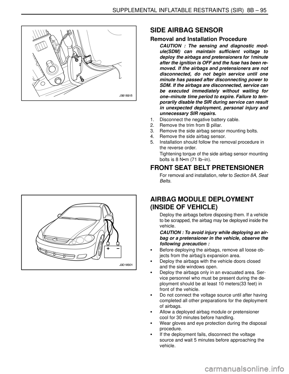
AIRBAG MODULE DEPLOYMENT
(INSIDE OF VEHICLE)
Deploy the airbags before disposing them. If a vehicle
to be scrapped, the airbag may be deployed inside the
vehicle.
CAUTION : To avoid injury while deploying an air-
bag or a pretensioner in the vehicle, observe the
following precaution :
S Before deploying the airbags, remove all loose ob-
jects from the airbag’s expansion area.
S Deploy the airbags with the vehicle doors closed
and the side windows open.
S Deploy the airbags only in an evacuated area. Ser-
vice personnel who must be present during the de-
ployment should be at least 10 meters(33 feet) in
front of the vehicle.
S Do not connect the voltage source until after having
completed all other preparations for the deployment
of airbags.
S Allow a deployed airbag module or pretensioner
cool for 30 minutes before handling.
S Wear gloves and eye protection during the disposal
procedure.
S If the deployment fails, disconnect the voltage
source and wait 5 minutes before approaching the
vehicle.