2004 DAEWOO LACETTI torque
[x] Cancel search: torquePage 1809 of 2643

AISIN AUTOMATIC TRANSAXLE 5A2 – 219
DAEWOO V–121 BL4
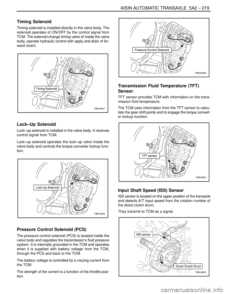
Timing Solenoid
Timing solenoid is installed directly in the valve body. The
solenoid operates of ON/OFF by the control signal from
TCM. The solenoid change timing valve of inside the valve
body, operate hydraulic control with apply and drain of for-
ward clutch.
Lock–Up Solenoid
Lock–up solenoid is installed in the valve body. It recieves
control signal from TCM.
Lock–up solenoid operates the lock–up valve inside the
valve body and controls the torque converter lockup func-
tion.
Pressure Control Solenoid (PCS)
The pressure control solenoid (PCS) is located inside the
valve body and regulates the transmission’s fluid pressure
system. It is internally grounded in the TCM and operates
when it is supplied with battery voltage from the TCM,
through the PCS and back to the TCM.
The battery voltage is controlled by a varying current from
the TCM.
The strength of the current is a function of the throttle posi-
tion.
Transmission Fluid Temperature (TFT)
Sensor
TFT sensor provides TCM with information on the trans-
mission fluid temperature.
The TCM uses information from the TFT sensor to calcu-
late the gear shift points and to engage the torque convert-
er lockup function.
Input Shaft Speed (ISS) Sensor
ISS sensor is located on the upper position of the transaxle
and detects A/T input speed from the rotation number of
the direct clutch drum.
They transmit to TCM as a signal.
Page 1811 of 2643

AISIN AUTOMATIC TRANSAXLE 5A2 – 221
DAEWOO V–121 BL4
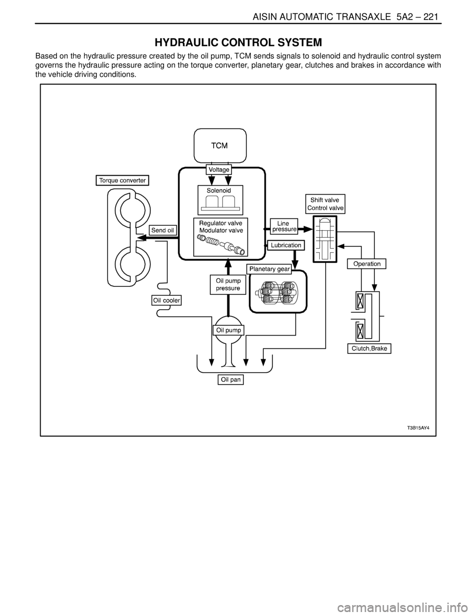
HYDRAULIC CONTROL SYSTEM
Based on the hydraulic pressure created by the oil pump, TCM sends signals to solenoid and hydraulic control system
governs the hydraulic pressure acting on the torque converter, planetary gear, clutches and brakes in accordance with
the vehicle driving conditions.
Page 1903 of 2643

6A – 2IPOWER STEERING SYSTEM
DAEWOO V–121 BL4
DIAGNOSIS
POWER STEERING SYSTEM
PRESSURE TEST
Tools Required
KM–354–B Pressure Test Gauge Kit
Check the fluid pressure as follows to determine whether
the trouble is in the pump or the gear unit.
Test Procedure
1. Check the power steering fluid level and the power
steering pump belt tension. Refer to ”Checking and
Adding Fluid” in this section and Section 6B, Power
Steering Pump.
2. Disconnect the high pressure line at the pump. Use
a small container to catch any fluid.
3. Connect the hose of the pressure test gauge kit
KM–354–B to the power steering pressure hose
from the power steering pump.
4. Place the gear selector lever in PARK (automatic
transaxle–equipped vehicles) or NEUTRAL (manual
transaxle–equipped vehicles). Set the parking
brake.
5. Open the gauge valve fully.
6. Start the engine and let it idle.
7. Turn the steering wheel from lock to lock several
times to warm the fluid to operating temperature.
8. Increase the engine speed to 1,500 rpm.
Notice : The power steering pump could be damaged if
the valve is fully closed for more than 5 seconds.
9. Close the gauge valve fully, and read the pressure.
The pump pressure with the valve closed should be
between 8,330 kPa to 8,820 kPa (1,208 psi to
1,279 psi). With electronic variable orifice, the pres-
sure should be between 8,500 kPa to 8,960 kPa
(1,233 psi to 1,299 psi).
10. Immediately open the gauge valve fully.
11. Turn the steering wheel all the way to the left and
the right. If the pressure is within the specified lim-
its, the problem is not in the pump. Check the pow-
er steering gear for leaks.
POWER STEERING SYSTEM LEAK
TEST
General Procedure
Inspect the following:
S The fluid reservoir for overfill.
S Fluid for aeration and overflow.
S The hoses for loose connections.
S The torsion bar, stub shaft and adjuster seals for
leaks.
S The component sealing surfaces for damage.
Important : Verify the exact point of the leak. The point
from which the fluid is dripping is not necessarily the point
at which the system is leaking. When service is required,
clean the leak area upon disassembly, replace the leaking
seal, check the component sealing surfaces for damage
and reset the torque bolt to specifications, where required.
External Leak Check
The purpose of this procedure is to pinpoint the location of
the leak. In some cases, the leak can be easily located, but
seepage–type leaks may be harder to find. To locate seep-
age leaks, use the following method:
1. With the engine off, wipe dry the complete power
steering system.
2. Check the power steering fluid level in the pump’s
reservoir. Adjust the fluid level as necessary. Refer
to ”Checking and Adding Fluid” in this section.
Notice : Do not hold the steering wheel at a stop for any
length of time as this can damage the power steering
pump.
3. Start the engine. Turn the steering wheel counter-
clockwise and clockwise from stop to stop several
times.
4. Find the exact area of the leak and repair it.
Page 1946 of 2643

POWER STEERING GEAR 6C – 29
DAEWOO V–121 BL4
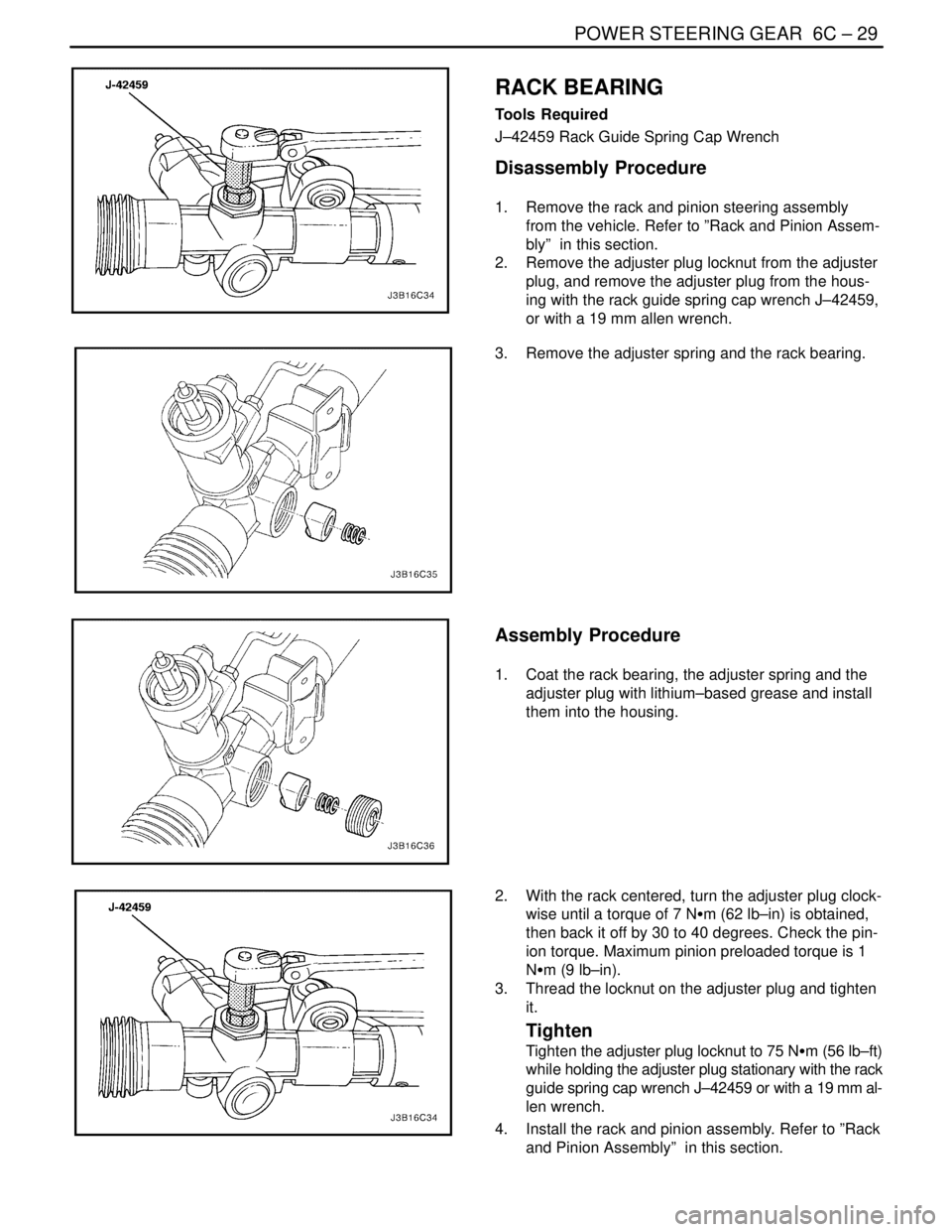
RACK BEARING
Tools Required
J–42459 Rack Guide Spring Cap Wrench
Disassembly Procedure
1. Remove the rack and pinion steering assembly
from the vehicle. Refer to ”Rack and Pinion Assem-
bly” in this section.
2. Remove the adjuster plug locknut from the adjuster
plug, and remove the adjuster plug from the hous-
ing with the rack guide spring cap wrench J–42459,
or with a 19 mm allen wrench.
3. Remove the adjuster spring and the rack bearing.
Assembly Procedure
1. Coat the rack bearing, the adjuster spring and the
adjuster plug with lithium–based grease and install
them into the housing.
2. With the rack centered, turn the adjuster plug clock-
wise until a torque of 7 NSm (62 lb–in) is obtained,
then back it off by 30 to 40 degrees. Check the pin-
ion torque. Maximum pinion preloaded torque is 1
NSm (9 lb–in).
3. Thread the locknut on the adjuster plug and tighten
it.
Tighten
Tighten the adjuster plug locknut to 75 NSm (56 lb–ft)
while holding the adjuster plug stationary with the rack
guide spring cap wrench J–42459 or with a 19 mm al-
len wrench.
4. Install the rack and pinion assembly. Refer to ”Rack
and Pinion Assembly” in this section.
Page 1947 of 2643

6C – 30IPOWER STEERING GEAR
DAEWOO V–121 BL4
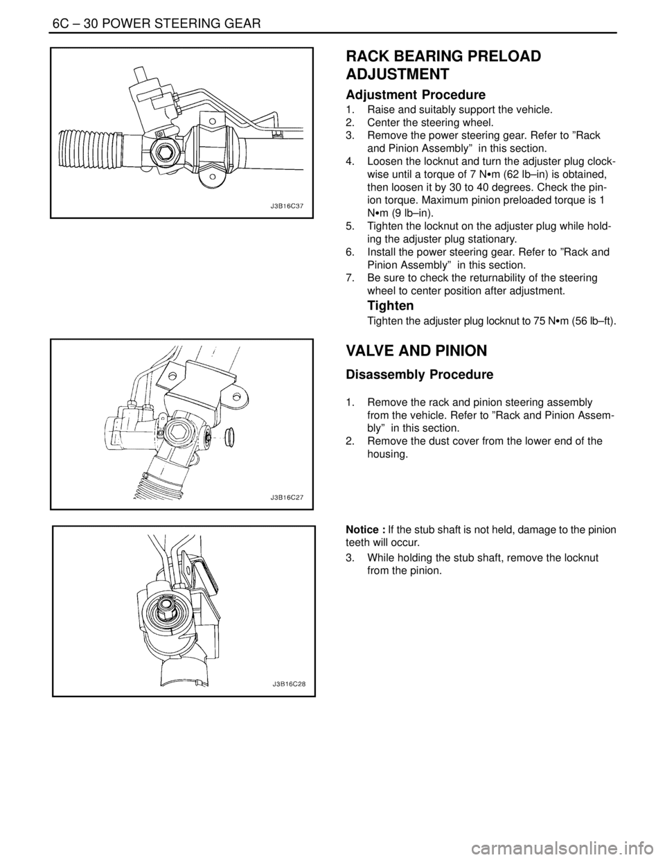
RACK BEARING PRELOAD
ADJUSTMENT
Adjustment Procedure
1. Raise and suitably support the vehicle.
2. Center the steering wheel.
3. Remove the power steering gear. Refer to ”Rack
and Pinion Assembly” in this section.
4. Loosen the locknut and turn the adjuster plug clock-
wise until a torque of 7 NSm (62 lb–in) is obtained,
then loosen it by 30 to 40 degrees. Check the pin-
ion torque. Maximum pinion preloaded torque is 1
NSm (9 lb–in).
5. Tighten the locknut on the adjuster plug while hold-
ing the adjuster plug stationary.
6. Install the power steering gear. Refer to ”Rack and
Pinion Assembly” in this section.
7. Be sure to check the returnability of the steering
wheel to center position after adjustment.
Tighten
Tighten the adjuster plug locknut to 75 NSm (56 lb–ft).
VALVE AND PINION
Disassembly Procedure
1. Remove the rack and pinion steering assembly
from the vehicle. Refer to ”Rack and Pinion Assem-
bly” in this section.
2. Remove the dust cover from the lower end of the
housing.
Notice : If the stub shaft is not held, damage to the pinion
teeth will occur.
3. While holding the stub shaft, remove the locknut
from the pinion.
Page 1950 of 2643

POWER STEERING GEAR 6C – 33
DAEWOO V–121 BL4
GENERAL DESCRIPTION
AND SYSTEM OPERATION
POWER RACK AND PINION
The power rack and pinion steering system has a rotary
control valve that directs hydraulic fluid coming from the
hydraulic pump to one side or the other side of the rack pis-
ton. The integral rack piston is attached to the rack. The
rack piston converts hydraulic pressure to a linear force
that moves the rack left or right. That force is then trans-
mitted through the tie rods to the steering knuckles, which
turn the wheels.
If power rack and pinion steering is not available, manual
rack and pinion control is used; however, with this system,
more steering effort is required. The movement of the
steering wheel is transferred to the pinion. The rotary
movement of the pinion is then transferred through the pin-
ion threads, which mesh with teeth on the rack, thereby
causing the rack to move in a linear direction.
A vane–type of hydraulic pump provides hydraulic pres-
sure for both steering systems.
SPEED SENSITIVE POWER
STEERING SYSTEM
The speed sensitive power steering (SSPS) system varies
the driver effort required to steer as the vehicle speed
changes. At low speeds, the system provides maximum
power assist for easy turning and parking maneuvers. At
higher speeds, the steering power is reduced to provide
the driver with firmer steering and directional stability. The
SSPS system accomplishes this by reducing the amount
of power steering fluid flow from the power steering pump
to the power steering gear as the vehicle speed increases.
When the vehicle is stationary, the SSPS system provides
maximum fluid flow to the steering gear. As the vehicle
speed increases, the fluid flow to the steering gear is de-
creased.
Control Module
The SSPS control module processes the vehicle speed in-
formation from the engine control module (ECM) and uses
the steering wheel rotation sensor to provide a control sig-
nal to the electronic variable orifice (EVO) actuator located
on the power steering pump.
Electronic Variable Orifice (EVO) Actuator
The electronic variable orifice (EVO) actuator is located on
the power steering pump and contains a solenoid– oper-
ated pintle valve. Fluid leaving the pump passes through
an orifice in the actuator tip. When the EVO actuator is
powered by the SSPS control module, the pintle moves
into the orifice and reduces the power steering fluid flow.As the vehicle speed increases, current from the SSPS
control module increases, and the pintle blocks more and
more of the orifice.
Steering Wheel Rotation Sensor
The steering wheel rotation sensor is located at the end of
the steering column housing and is used to send a signal
to the controller when abrupt or evasive steering maneu-
vers are needed.
Power Steering Pressure Hose
SSPS vehicles have a specific pressure hose assembly
which includes an in–line check valve in the rack and pin-
ion assembly. This reduces the amount of steering wheel
”kick” when driving over irregular road surfaces while oper-
ating at speeds with reduced flow rate and pressure.
Power Rack and Pinion
Except for differences in valve machining, the design of
the SSPS power rack and pinion assembly is the same as
for the a non–SSPS system. The steering wheel move-
ment is transferred to the pinion via the intermediate shaft.
The pinion moves the rack left or right through meshing the
pinion and the rack teeth. The force is then transmitted
through the tie rods and steering knuckle to steer the
wheels.
The power rack and pinion steering system has a rotary
control valve which directs the hydraulic fluid from the
power steering pump to one side or the other side of the
rack piston. The piston is attached to the rack and uses hy-
draulic pressure to move the rack left or right. The rotary
control valve regulates the degree of assist by responding
to the driver’s torque input.
If hydraulic assist is not available, manual control is main-
tained. However, under this condition, more steering effort
is required.
Power Steering Pump
The standard vane–type pump, which provides hydraulic
pressure for the system, incorporates a special discharge
fitting to hold the EVO actuator.
System Operation
System operation originates with input from the vehicle
speed sensor via the engine control module to the SSPS
control module. The SSPS control module sends a signal
to the SSPS actuator to vary the rate of fluid flow output
by the power steering pump.
Circuit Operation
The SSPS system uses inputs from the speed sensor and
steering wheel rotation sensor to the SSPS controller to
determine the desired amount of power steering assist.
The SSPS control module constantly compares the
amount of current flowing through the EVO actuator to the
desired current it has calculated. The EVO actuator has a
pintle that moves in and out of an orifice, regulating power
Page 1974 of 2643

6E – 20ISTEERING WHEEL AND COLUMN
DAEWOO V–121 BL4
GENERAL DESCRIPTION
AND SYSTEM OPERATION
STEERING WHEEL AND COLUMN
CAUTION : To ensure the energy–absorbing action of
the steering column, it is important to use only the
specified screws, bolts, and nuts, tightened to the
specified torque.
In addition to the steering function, the steering column
provides safety and security.
The energy–absorbing column is designed to compress in
a front–end collision to lessen the chance of driver injury.
The ignition switch and the lock are mounted on the col-
umn, allowing the ignition and steering operations to be
locked to inhibit theft of the car.
The column levers trigger the turn signals, the headlight
beams, and the windshield washer and wipers.The tilt steering column uses telescopic function to allow
the steering wheel to tilt up and down in and out. This en-
ables the driver to adjust the steering wheel to a comfort-
able position.
Notice : Apply a thin coat of lithium grease to all friction
points when reassembling.
The column may be disassembled and reassembled easi-
ly.IGNITION KEY REMINDER
The ignition key reminder alerts the driver that the key is
still in the ignition when the driver attempts to exit the ve-
hicle.
An internal switch in the ignition lock cylinder supplies bat-
tery voltage to the reminder chime module when all of the
following conditions are true:
S The key is in the ignition switch.
S The ignition is OFF.
S The driver’s door is open.
For information on removal and installation of the reminder
chime module, refer to Section 9E, Instrumentation/Driver
Information.
Page 2013 of 2643

MANUAL CONTROL HEATING, VENTILATION AND AIR CONDITIONING SYSTEM 7B – 11
DAEWOO V–121 BL4
LEAK TESTING REFRIGERANT
SYSTEM
Test for leaks whenever you suspect a refrigerant leak in
the system. You should also test for leaks whenever you
perform a service operation which results in disturbing the
lines or the connections. Leaks are commonly found at the
refrigerant fittings or at the connections. Leaks are com-
monly caused by the following problems:
S Improper torque.
S Damaged O–ring seals.
S Dirt or lint on the O–ring seals.
Liquid Leak Detectors
Use a liquid leak detector solution on locations such as fit-
tings. Apply the solution to the area in question with the
swab that is supplied with the solution. Look for bubbles
to appear. This will indicate the existence and the location
of any leak.
For areas where this is not practical, such as sections of
the evaporator and the condenser, an electronic leak de-
tector is more useful.
Electronic Leak Detectors
Follow the manufacturer’s instructions for calibration, op-
eration, and maintenance of an electronic leak detector.
Battery condition is especially important to the accuracy
of a portable model. Set the detector to R–134a before be-
ginning the test.
Notice : Electronic leak detectors are sensitive to wind-
shield washing solutions, solvents and cleaners, and cer-
tain vehicle adhesives. Surfaces must be clean to prevent
false readings. Make sure that all surfaces are dry to pre-
vent damage to the detector.
General Testing Instructions
1. Follow the entire path of the refrigerant system.
2. Completely circle each joint at 25 to 50 mm (1 to 2
inches) per second.
3. Hold the probe tip within 6 mm (1/4 inch) of the sur-
face.4. Do not block the air intake.
5. The audible tone changes from 1 to 2 clicks per
second into a solid alarm if there is a leak. Adjust
the balance control to maintain 1 to 2 clicks per
second.
6. Test all of the following areas, even after one leak
has been confirmed:
S Evaporator inlet and outlet.
S Receiver–drier inlet and outlet.
S Condenser inlet and outlet.
S Brazed and welded areas.
S Damaged areas.
S Hose couplings.
S Compressor rear head.
S All fittings and joints.
Testing Service Ports/Access Valves
The sealing caps provide protection for the service ports.
Make sure that these caps are not missing or loose. Al-
ways use the correct cap for each port.
Testing the Evaporator Core
Leaks in the evaporator core are difficult to find. Test the
evaporator core using the following procedure:
1. Run the blower fan at the maximum speed setting
for at least 15 minutes.
2. Turn the blower OFF.
3. Wait for 10 minutes.
4. Remove the blower motor resistor. Refer to Section
7A, Heating and Ventilation System.
5. Insert the leak detector probe as close as possible
to the evaporator core. The detector will indicate a
leak with a solid alarm.
6. Use a flashlight to search for refrigerant oil on the
core surface.
Testing the Compressor Shaft Seal
1. Blow shop air behind and in front of the compressor
clutch/pulley for at least 15 seconds.
2. Wait 1 to 2 minutes.
3. Probe the area in front of the pulley. If the detector
emits a solid alarm, there is a leak.