Page 1535 of 2643

5A1 – 186IZF 4 HP 16 AUTOMATIC TRANSAXLE
DAEWOO V–121 BL4
RangePark/
Neutr
alRever
seD321
GearNR1st2nd3rd4th1st2nd3rd1st2nd1st
Solenoid Valve
1ONON/
OFFON/
OFFON/
OFFON/
OFFON/
OFFON/
OFFON/
OFFON/
OFFON/
OFFON/
OFFON/
OFF
Solenoid Valve
2ONONONOFFOFFOFFONOFFOFFONOFFON
Line Pressure
Control Sole-
noid Valve 3
(EDS 3)OFFOFFOFFONON/
OFFON/
OFFOFFONON/
OFFOFFONOFF
Line Pressure
Control Sole-
noid Valve 4
(EDS 4)ONOFFONONONOFFONONONONONON
Line Pressure
Control Sole-
noid Valve 5
(EDS 5)OFFOFFONONOFFOFFONONOFFONONON
Line Pressure
Control Sole-
noid Valve 6
(EDS 6)ONOFFONONONOFFONONONONONON
Brake BAAAAAAAA
Brake CH
Brake DH
Clutch EAAAAAA
Brake FHHHHHHH
Lock–up
ClutchA
A = Applied
H = Holding
ON = The solenoid is energized.
OFF = The solenoid is de–energized.
** = Manual Second–Third gear is only available above approximately 100 km/h (62 mph).
*** = Manual First–Second gear is only available above approximately 60 km/h (37 mph).
Note : Manual First–Third gear is also possible at high vehicle speed as a safety feature.
DIAGNOSTIC TROUBLE CODE(DTC) P1885
3–1 SHIFT MALFUNCTION
Circuit Description
The special feature of 4HP 16 Auto Transaxle is that it op-
erates without freewheels. Shifting between individual
gears takes place by means of overlapping clutch engage-
ment and release.
The advantage of overlap shifting are as follows:
– The transaxle can be of more compact design
and is lighter on account of the absence of free-
wheels and the lower number of shift elements.– Lower drag losses, i.e. higher efficiency.
– Lower peak torque acting on the components and
driveline.
However, overlap shifting necessitates high–performance
hardware and software, and precision engine signals.
Conditions for Setting the DTC
S Transmission oil temperature is greater than –10°C
(14°F).
S Selector lever is not in N(Neutral), P(Park) position.
S System voltage is greater than 9 volts.
Page 1537 of 2643

5A1 – 188IZF 4 HP 16 AUTOMATIC TRANSAXLE
DAEWOO V–121 BL4
RangePark/
Neutr
alRever
seD321
GearNR1st2nd3rd4th1st2nd3rd1st2nd1st
Solenoid Valve
1ONON/
OFFON/
OFFON/
OFFON/
OFFON/
OFFON/
OFFON/
OFFON/
OFFON/
OFFON/
OFFON/
OFF
Solenoid Valve
2ONONONOFFOFFOFFONOFFOFFONOFFON
Line Pressure
Control Sole-
noid Valve 3
(EDS 3)OFFOFFOFFONON/
OFFON/
OFFOFFONON/
OFFOFFONOFF
Line Pressure
Control Sole-
noid Valve 4
(EDS 4)ONOFFONONONOFFONONONONONON
Line Pressure
Control Sole-
noid Valve 5
(EDS 5)OFFOFFONONOFFOFFONONOFFONONON
Line Pressure
Control Sole-
noid Valve 6
(EDS 6)ONOFFONONONOFFONONONONONON
Brake BAAAAAAAA
Brake CH
Brake DH
Clutch EAAAAAA
Brake FHHHHHHH
Lock–up
ClutchA
A = Applied
H = Holding
ON = The solenoid is energized.
OFF = The solenoid is de–energized.
** = Manual Second–Third gear is only available above approximately 100 km/h (62 mph).
*** = Manual First–Second gear is only available above approximately 60 km/h (37 mph).
Note : Manual First–Third gear is also possible at high vehicle speed as a safety feature.
DIAGNOSTIC TROUBLE CODE(DTC) P1886
4–2 SHIFT MALFUNCTION
Circuit Description
The special feature of 4HP 16 Auto Transaxle is that it op-
erates without freewheels. Shifting between individual
gears takes place by means of overlapping clutch engage-
ment and release.
The advantage of overlap shifting are as follows:
– The transaxle can be of more compact design
and is lighter on account of the absence of free-
wheels and the lower number of shift elements.– Lower drag losses, i.e. higher efficiency.
– Lower peak torque acting on the components and
driveline.
However, overlap shifting necessitates high–performance
hardware and software, and precision engine signals.
Conditions for Setting the DTC
S Transmission oil temperature is greater than –10°C
(14°F).
S Selector lever is not in N(Neutral), P(Park) position.
S System voltage is greater than 9 volts.
Page 1541 of 2643

5A1 – 192IZF 4 HP 16 AUTOMATIC TRANSAXLE
DAEWOO V–121 BL4
FLUID LEVEL SET AFTER SERVICE
1. Add transaxle fluid through the fill cap hole prior to
adjusting the fluid level. The amount of fluid to add
should be based on the type of service done.
Adjustment Notice
S Use ESSO LT 71141 transaxle fluid only.
S Oil pan removed : 4L (4.2 qt)
S Torque converter removed : 2L (2.1 qt)
S Complete overhaul : 6.7L (7.1qt)
S Drain plug removed : 4L (4.2 qt)
2. Check the transaxle fluid level. Refer to ”Transaxle
Fluid Level Checking Procedure” in this section.
3. Add additional fluid through the fill cap hole in 0.5
liter (0.5 quart) increments until the fluid comes out
through the plug hole.
4. Allow the fluid to finish draining out through the plug
hole, then install the fluid level plug.
5. When the fluid level setting procedure is completed,
wipe any fluid from the transaxle case with a rag or
shop towel. Also, check that the fluid fill cap and the
vent tube are properly installed.
REPAIRING FLUID LEAKS
Locating Leaks
General Method
1. Verify that the leak is transaxle fluid.
2. Thoroughly clean the suspected leak area.
3. Operate the vehicle for about 25 kilometers (15
miles) or until the transaxle reaches normal operat-
ing temperature, 88°C (190°F).
4. Park the vehicle over clean paper or cardboard.
5. Turn the engine off and look for fluid spots on the
paper.
6. Make the necessary repairs to correct the leak.
Powder Method
1. Thoroughly clean the suspected leak area.
2. Apply an aerosol–type powder (foot powder) to the
suspected leak area.
3. Operate the vehicle for about 25 kilometers (15
miles) or until the transaxle reaches normal operat-
ing temperature, 88°C (190°F).
4. Turn the engine off.
5. Inspect the suspected leak area and trace the leak
path through the powder to find the source of the
leak.
6. Make the necessary repairs.
Page 1557 of 2643
5A1 – 208IZF 4 HP 16 AUTOMATIC TRANSAXLE
DAEWOO V–121 BL4
10. Raise and suitably support the vehicle.
11. Drain the transaxle fluid.
12. Remove the oil cooler pipes from the transaxle. Re-
fer to ”Oil Cooler Pipes/Hoses” in this section.
13. Remove the drive axle. Refer to Section 3A, Auto-
matic Drive Axle.
14. Remove the starter motor. Refer to Section 1E, En-
gine Electrical.
15. Remove the torque converter bolts.
16. Support the transaxle.
17. Remove the rear transaxle mounting bracket bolts
(a) and damping block connection bolt and nut (b).
18. Support the transaxle assembly using the transaxle
support fixture DW260–010.
Page 1559 of 2643
5A1 – 210IZF 4 HP 16 AUTOMATIC TRANSAXLE
DAEWOO V–121 BL4
4. Install the rear transaxle mounting bracket bolts (a).
Tighten
Tighten the rear transaxle mounting bracket bolts (a)
to 62 NSm (45 lb–ft).
5. Install the damping block connection bolt and nut
(b).
Tighten
Tighten the damping block connection bolt and nut (b)
to 68 NSm (50 lb–ft).
6. Install the torque converter bolts.
7. Install the starter motor. Refer to Section 1E, En-
gine Electrical.
8. Install the drive axle. Refer to Section 3A, Automat-
ic Drive Axle.
9. Install the oil cooler pipes from the transaxle. Refer
to ”Oil Cooler Pipes/Hoses” in this section.
10. Lower the vehicle.
11. Install the left transaxle mounting bracket. Refer to
”Left Transaxle Mounting Bracket” in this section.
Page 1561 of 2643

5A1 – 212IZF 4 HP 16 AUTOMATIC TRANSAXLE
DAEWOO V–121 BL4
UNIT REPAIR
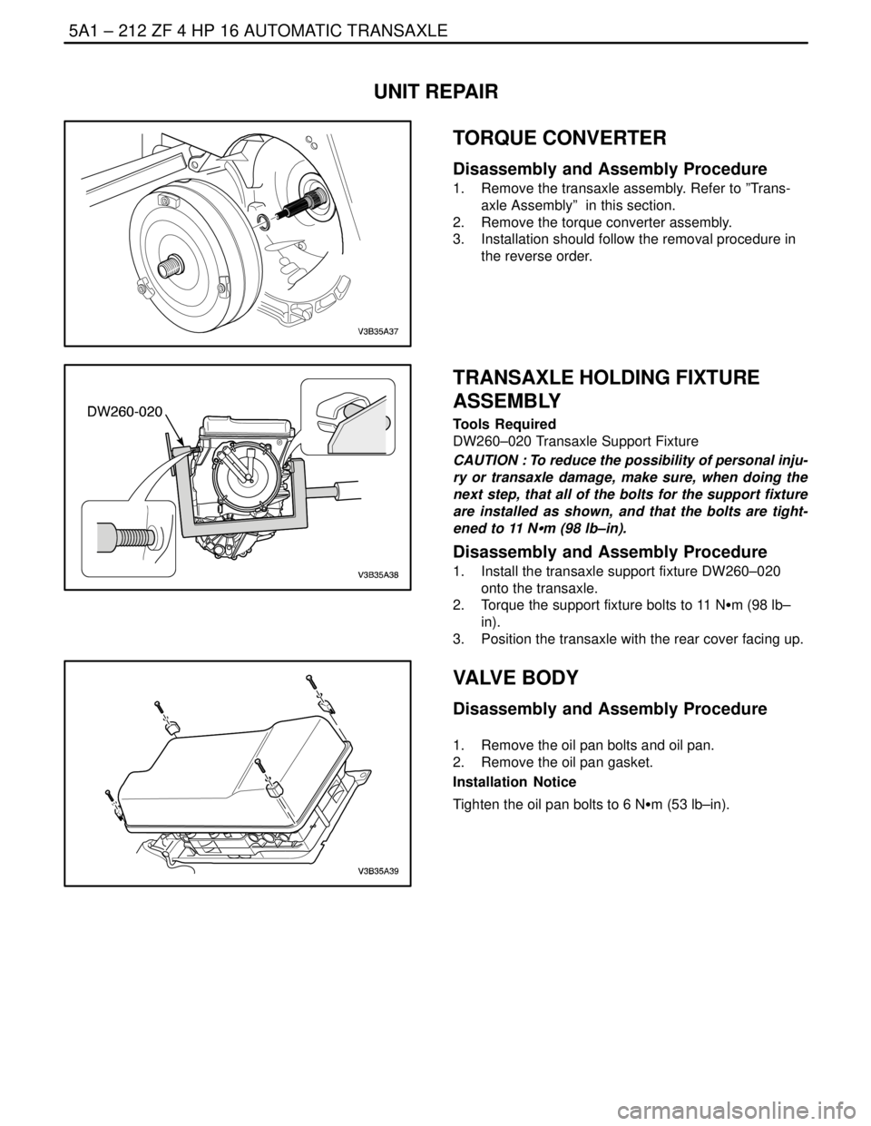
TORQUE CONVERTER
Disassembly and Assembly Procedure
1. Remove the transaxle assembly. Refer to ”Trans-
axle Assembly” in this section.
2. Remove the torque converter assembly.
3. Installation should follow the removal procedure in
the reverse order.
TRANSAXLE HOLDING FIXTURE
ASSEMBLY
Tools Required
DW260–020 Transaxle Support Fixture
CAUTION : To reduce the possibility of personal inju-
ry or transaxle damage, make sure, when doing the
next step, that all of the bolts for the support fixture
are installed as shown, and that the bolts are tight-
ened to 11 NSm (98 lb–in).
Disassembly and Assembly Procedure
1. Install the transaxle support fixture DW260–020
onto the transaxle.
2. Torque the support fixture bolts to 11 NSm (98 lb–
in).
3. Position the transaxle with the rear cover facing up.
VALVE BODY
Disassembly and Assembly Procedure
1. Remove the oil pan bolts and oil pan.
2. Remove the oil pan gasket.
Installation Notice
Tighten the oil pan bolts to 6 NSm (53 lb–in).
Page 1573 of 2643
5A1 – 224IZF 4 HP 16 AUTOMATIC TRANSAXLE
DAEWOO V–121 BL4
10. Turn the disc carrier C/D by 180°.
11. Using assembly bracket Press down cup spring and
take out the snap ring.
12. Remove the disc set D.
13. Installation should follow the removal procedure in
the reverse order.
DIFFERENTIAL
Disassembly and Assembly Procedure
1. Remove the torque converter housing. Refer to
”Torque Converter” in this section.
2. Lift out the differential.
3. Installation should follow the removal procedure in
the reverse order.
Removal Notice
S Don’t disassemble the differential to avoid incorrect
operation.
SIDE SHAFT
Disassembly and Assembly Procedure
1. Remove the differential. Refer to ”Differential” in
this section.
2. Tilt and remove the side shaft.
3. Installation should follow the removal procedure in
the reverse order.
Removal Notice
S Don’t disassemble the differential to avoid incorrect
operation.
Page 1576 of 2643

ZF 4 HP 16 AUTOMATIC TRANSAXLE 5A1 – 227
DAEWOO V–121 BL4
2. Find the disc set’s thickness. Refer to the below
table.
PF
Disc set’s Thickness
3.01~3.19mm1.8mm
3.20~3.48mm2.1mm
3.49~3.88mm2.5mm
3.89~4.08mm2.7mm
4.09~4.30mm3.0mm
PE is 4.20mm so, the disc set’s thickness is
3.0mm.
3. Replace clutch B’s setting disc. (3.0mm)
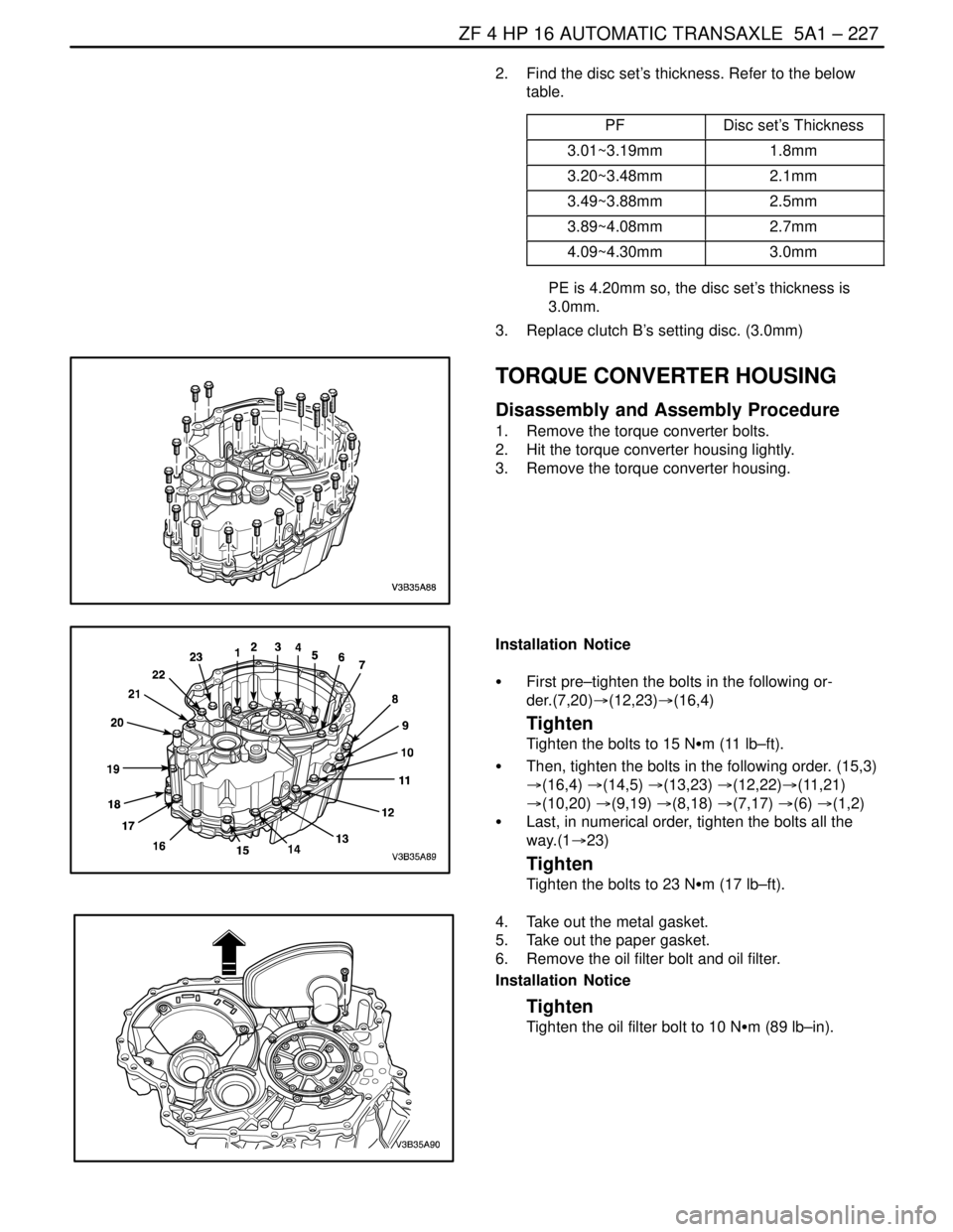
TORQUE CONVERTER HOUSING
Disassembly and Assembly Procedure
1. Remove the torque converter bolts.
2. Hit the torque converter housing lightly.
3. Remove the torque converter housing.
Installation Notice
S First pre–tighten the bolts in the following or-
der.(7,20)�(12,23)�(16,4)
Tighten
Tighten the bolts to 15 NSm (11 lb–ft).
S Then, tighten the bolts in the following order. (15,3)
�(16,4) �(14,5) �(13,23) �(12,22)�(11,21)
�(10,20) �(9,19) �(8,18) �(7,17) �(6) �(1,2)
S Last, in numerical order, tighten the bolts all the
way.(1�23)
Tighten
Tighten the bolts to 23 NSm (17 lb–ft).
4. Take out the metal gasket.
5. Take out the paper gasket.
6. Remove the oil filter bolt and oil filter.
Installation Notice
Tighten
Tighten the oil filter bolt to 10 NSm (89 lb–in).