Page 1298 of 2234
550RQ±02
55±6
±
HEATER & AIR CONDITIONER AIR CONDITIONING SYSTEM
AVENSIS REPAIR MANUAL (RM1018E)
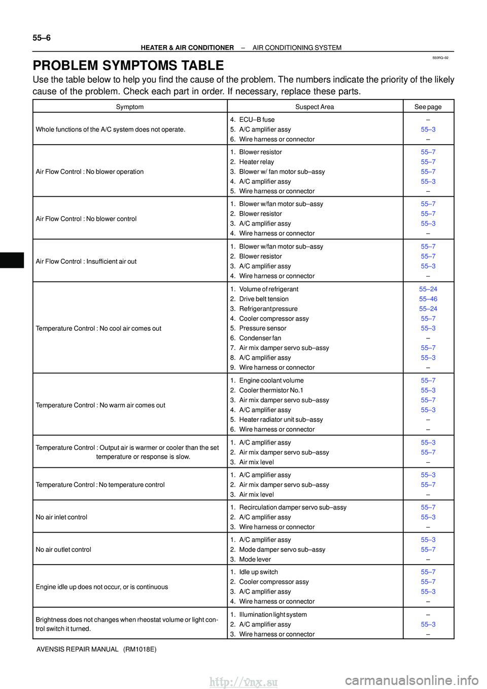
PROBLEM SYMPTOMS TABLE
Use the table below to help you find the cause of the problem. The numbers \
indicate the priority of the likely
cause of the problem. Check each part in order. If necessary, replace these parts.
SymptomSuspect AreaSee page
Whole functions of the A/C system does not operate.
4. ECU±B fuse
5. A/C amplifier assy
6. Wire harness or connector±
55±3 ±
Air Flow Control : No blower operation
1. Blower resistor
2. Heater relay
3. Blower w/ fan motor sub±assy
4. A/C amplifier assy
5. Wire harness or connector55±7
55±7
55±7
55±3±
Air Flow Control : No blower control
1. Blower w/fan motor sub±assy
2. Blower resistor
3. A/C amplifier assy
4. Wire harness or connector55±7
55±7
55±3
±
Air Flow Control : Insufficient air out
1. Blower w/fan motor sub±assy
2. Blower resistor
3. A/C amplifier assy
4. Wire harness or connector55±7
55±7
55±3±
Temperature Control : No cool air comes out
1. Volume of refrigerant
2. Drive belt tension
3. Refrigerant pressure
4. Cooler compressor assy
5. Pressure sensor
6. Condenser fan
7. Air mix damper servo sub±assy
8. A/C amplifier assy
9. Wire harness or connector55±24
55±46
55±2455±7
55±3 ±
55±7
55±3 ±
Temperature Control : No warm air comes out
1. Engine coolant volume
2. Cooler thermistor No.1
3. Air mix damper servo sub±assy
4. A/C amplifier assy
5. Heater radiator unit sub±assy
6. Wire harness or connector55±7
55±3
55±7
55±3±
±
Temperature Control : Output air is warmer or cooler than the set
temperature or response is slow.1. A/C amplifier assy
2. Air mix damper servo sub±assy
3. Air mix level55±3
55±7
±
Temperature Control : No temperature control
1. A/C amplifier assy
2. Air mix damper servo sub±assy
3. Air mix level55±3
55±7±
No air inlet control
1. Recirculation damper servo sub±assy
2. A/C amplifier assy
3. Wire harness or connector55±7
55±3±
No air outlet control
1. A/C amplifier assy
2. Mode damper servo sub±assy
3. Mode lever55±3
55±7±
Engine idle up does not occur, or is continuous
1. Idle up switch
2. Cooler compressor assy
3. A/C amplifier assy
4. Wire harness or connector55±7
55±7
55±3±
Brightness does not changes when rheostat volume or light con-
trol switch it turned.1. Illumination light system
2. A/C amplifier assy
3. Wire harness or connector±
55±3 ±
http://vnx.su
Page 1310 of 2234
550ZG±01
������������������I12508
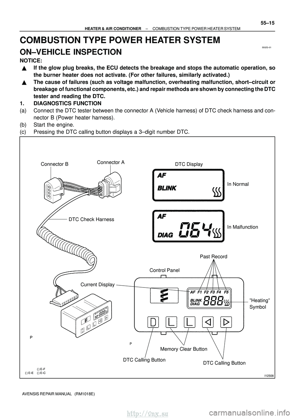
Connector BDTC Check Harness
Current Display Control Panel
Past Record
DTC Display
Memory Clear Button
DTC Calling Button DTC Calling ButtonºHeatingº
Symbol
In Normal
In Malfunction
Connector A
±
HEATER & AIR CONDITIONER COMBUSTION TYPE POWER HEATER SYSTEM
55±15
AVENSIS REPAIR MANUAL (RM1018E)
COMBUSTION TYPE POWER HEATER SYSTEM
ON±VEHICLE INSPECTION
NOTICE:
�If the glow plug breaks, the ECU detects the breakage and stops the auto\
matic operation, so
the burner heater does not activate. (For other failures, similarly act\
ivated.)
�The cause of failures (such as voltage malfunction, overheating malfunctio\
n, short±circuit or
breakage of functional components, etc.) and repair methods are shown by connecting the DTC
tester and reading the DTC.
1. DIAGNOSTICS FUNCTION
(a) Connect the DTC tester between the connector A (Vehicle harness) of DTC check harness and con- nector B (Power heater harness).
(b) Start the engine.
(c) Pressing the DTC calling button displays a 3±digit number DTC.
http://vnx.su
Page 1317 of 2234
550ZE±01
±
HEATER & AIR CONDITIONER ELECTRICAL TYPE POWER HEATER SYSTEM
55±13
AVENSIS REPAIR MANUAL (RM1018E)
ELECTRICAL TYPE POWER HEATER SYSTEM
PROBLEM SYMPTOMS TABLE
Use the table below to help you find the cause of the problem. The numbers \
indicate the priority of the likely
cause of the problem. Check each part in order. If necessary, replace these parts.
SymptomSuspect AreaSee page
PTC heater does not operate, when perform in these conditions:
�Engine coolant temp.: 70 �C (158� F) or below
� Engine speed: 650 rpm or above
� Temperature control selector: MAX. HOT
� Ambient temperature: Below 10 �C (50� F)
1. HTR1 Fuse
2. HTR2 Fuse
3. HTR1 relay
4. HTR2 relay
5. PTC heater
6. ECM
7. Wire harness±
±
±
±
55±14
±
±
http://vnx.su
Page 1319 of 2234
550ZE±01
±
HEATER & AIR CONDITIONER ELECTRICAL TYPE POWER HEATER SYSTEM
55±13
AVENSIS REPAIR MANUAL (RM1018E)
ELECTRICAL TYPE POWER HEATER SYSTEM
PROBLEM SYMPTOMS TABLE
Use the table below to help you find the cause of the problem. The numbers \
indicate the priority of the likely
cause of the problem. Check each part in order. If necessary, replace these parts.
SymptomSuspect AreaSee page
PTC heater does not operate, when perform in these conditions:
�Engine coolant temp.: 70 �C (158� F) or below
� Engine speed: 650 rpm or above
� Temperature control selector: MAX. HOT
� Ambient temperature: Below 10 �C (50� F)
1. HTR1 Fuse
2. HTR2 Fuse
3. HTR1 relay
4. HTR2 relay
5. PTC heater
6. ECM
7. Wire harness±
±
±
±
55±14
±
±
http://vnx.su
Page 1322 of 2234
I35349
I35350
I35350
I35349
±
HEATER & AIR CONDITIONER HEATER ASSY
55±101
AVENSIS REPAIR MANUAL (RM1018E)
6. REMOVE HEATER ASSY
(a) Using pliers, grip the claws of the clip and slide the clip to
disconnect the heater fuel hose.
HINT:
Prepare a support plate and waste to catch the leaked fuel.
(b) Disconnect the connector.
(c) Remove the 2 bolts and the heater assy.
7. INSTALL HEATER ASSY
(a) Install the heater assy with the 2 bolts. Torque: 7.5 N �m (76 kgf �cm, 66 in. �lbf)
(b) Connect the connector.
(c) Install the heater fuel hose.
HINT:
Prepare a support plate and waste to catch the leaked fuel.
8.INSTALL FUEL FILTER ASSY (See page 11±82)
9.INSTALL AIR CLEANER ASSY (See page 11±82)
10.ADD ENGINE COOLANT (See page 16±44)
11.CHECK FOR ENGINE COOLANT LEAKS (See page 16±37)
12.CHECK FUEL LEAK (See page 11±56)
http://vnx.su
Page 1325 of 2234
550Z7±01
I35292
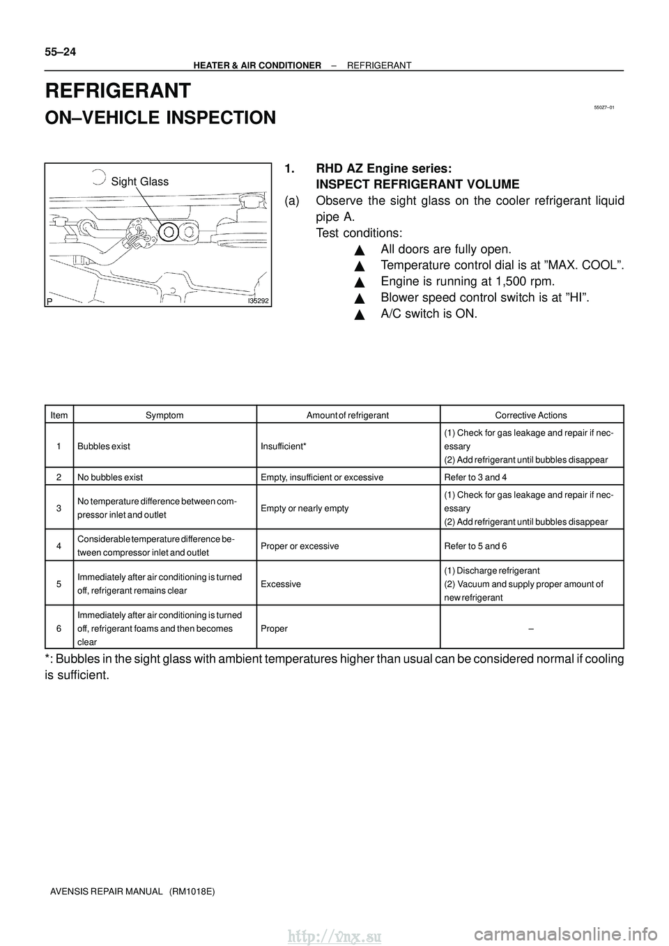
Sight Glass
55±24
±
HEATER & AIR CONDITIONER REFRIGERANT
AVENSIS REPAIR MANUAL (RM1018E)
REFRIGERANT
ON±VEHICLE INSPECTION
1. RHD AZ Engine series: INSPECT REFRIGERANT VOLUME
(a) Observe the sight glass on the cooler refrigerant liquid pipe A.
Test conditions:
�All doors are fully open.
�Temperature control dial is at ºMAX. COOLº.
�Engine is running at 1,500 rpm.
�Blower speed control switch is at ºHIº.
�A/C switch is ON.
ItemSymptomAmount of refrigerantCorrective Actions
1Bubbles existInsufficient*
(1) Check for gas leakage and repair if nec-
essary
(2) Add refrigerant until bubbles disappear
2No bubbles existEmpty, insufficient or excessiveRefer to 3 and 4
3No temperature difference between com-
pressor inlet and outletEmpty or nearly empty
(1) Check for gas leakage and repair if nec-
essary
(2) Add refrigerant until bubbles disappear
4Considerable temperature difference be-
tween compressor inlet and outletProper or excessiveRefer to 5 and 6
5Immediately after air conditioning is turned
off, refrigerant remains clearExcessive
(1) Discharge refrigerant
(2) Vacuum and supply proper amount of
new refrigerant
6
Immediately after air conditioning is turned
off, refrigerant foams and then becomes
clear
Proper±
*: Bubbles in the sight glass with ambient temperatures higher than usual \
can be considered normal if cooling
is sufficient.
http://vnx.su
Page 1328 of 2234
I22118
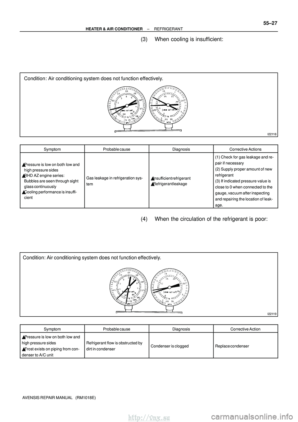
Condition: Air conditioning system does not function effectively.
I22119
Condition: Air conditioning system does not function effectively.
±
HEATER & AIR CONDITIONER REFRIGERANT
55±27
AVENSIS REPAIR MANUAL (RM1018E)
(3) When cooling is insufficient:
SymptomProbable causeDiagnosisCorrective Actions
�Pressure is low on both low and
high pressure sides
� RHD AZ engine series:
Bubbles are seen through sight
glass continuously
� Cooling performance is insuffi-
cient
Gas leakage in refrigeration sys-
tem�Insufficient refrigerant
� Refrigerant leakage
(1) Check for gas leakage and re-
pair if necessary
(2) Supply proper amount of new
refrigerant
(3) If indicated pressure value is
close to 0 when connected to the
gauge, vacuum after inspecting
and repairing the location of leak-
age.
(4) When the circulation of the refrigerant is poor:
SymptomProbable causeDiagnosisCorrective Action
� Pressure is low on both low and
high pressure sides
� Frost exists on piping from con-
denser to A/C unit
Refrigerant flow is obstructed by
dirt in condenserCondenser is cloggedReplace condenser
http://vnx.su
Page 1329 of 2234
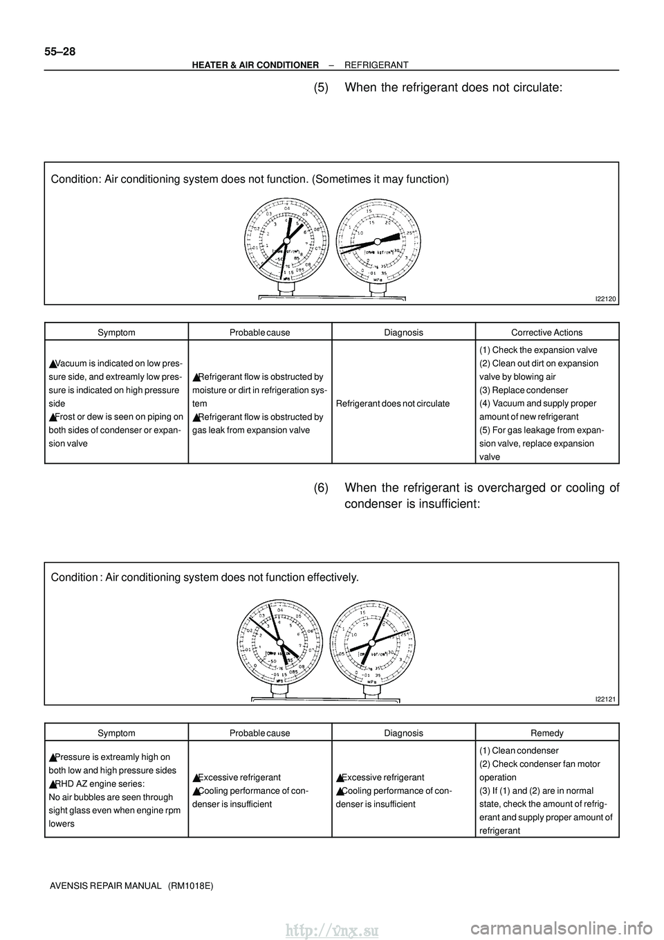
I22120
Condition: Air conditioning system does not function. (Sometimes it may function)\
I22121
Condition : Air conditioning system does not function effectively.
55±28
±
HEATER & AIR CONDITIONER REFRIGERANT
AVENSIS REPAIR MANUAL (RM1018E)
(5) When the refrigerant does not circulate:
SymptomProbable causeDiagnosisCorrective Actions
� Vacuum is indicated on low pres-
sure side, and extreamly low pres-
sure is indicated on high pressure
side
� Frost or dew is seen on piping on
both sides of condenser or expan-
sion valve
� Refrigerant flow is obstructed by
moisture or dirt in refrigeration sys-
tem
� Refrigerant flow is obstructed by
gas leak from expansion valve
Refrigerant does not circulate
(1) Check the expansion valve
(2) Clean out dirt on expansion
valve by blowing air
(3) Replace condenser
(4) Vacuum and supply proper
amount of new refrigerant
(5) For gas leakage from expan-
sion valve, replace expansion
valve
(6) When the refrigerant is overcharged or cooling of condenser is insufficient:
SymptomProbable causeDiagnosisRemedy
� Pressure is extreamly high on
both low and high pressure sides
� RHD AZ engine series:
No air bubbles are seen through
sight glass even when engine rpm
lowers
� Excessive refrigerant
� Cooling performance of con-
denser is insufficient� Excessive refrigerant
� Cooling performance of con-
denser is insufficient
(1) Clean condenser
(2) Check condenser fan motor
operation
(3) If (1) and (2) are in normal
state, check the amount of refrig-
erant and supply proper amount of
refrigerant
http://vnx.su