Page 1131 of 2234
F05383
Air
Hose Side Vacuum Pump Side
Air
F08981
F08982
New O±Ring
F08970
±
BRAKE VACUUM PUMP ASSY (1CD±FTV)
32±37
AVENSIS REPAIR MANUAL (RM1018E)
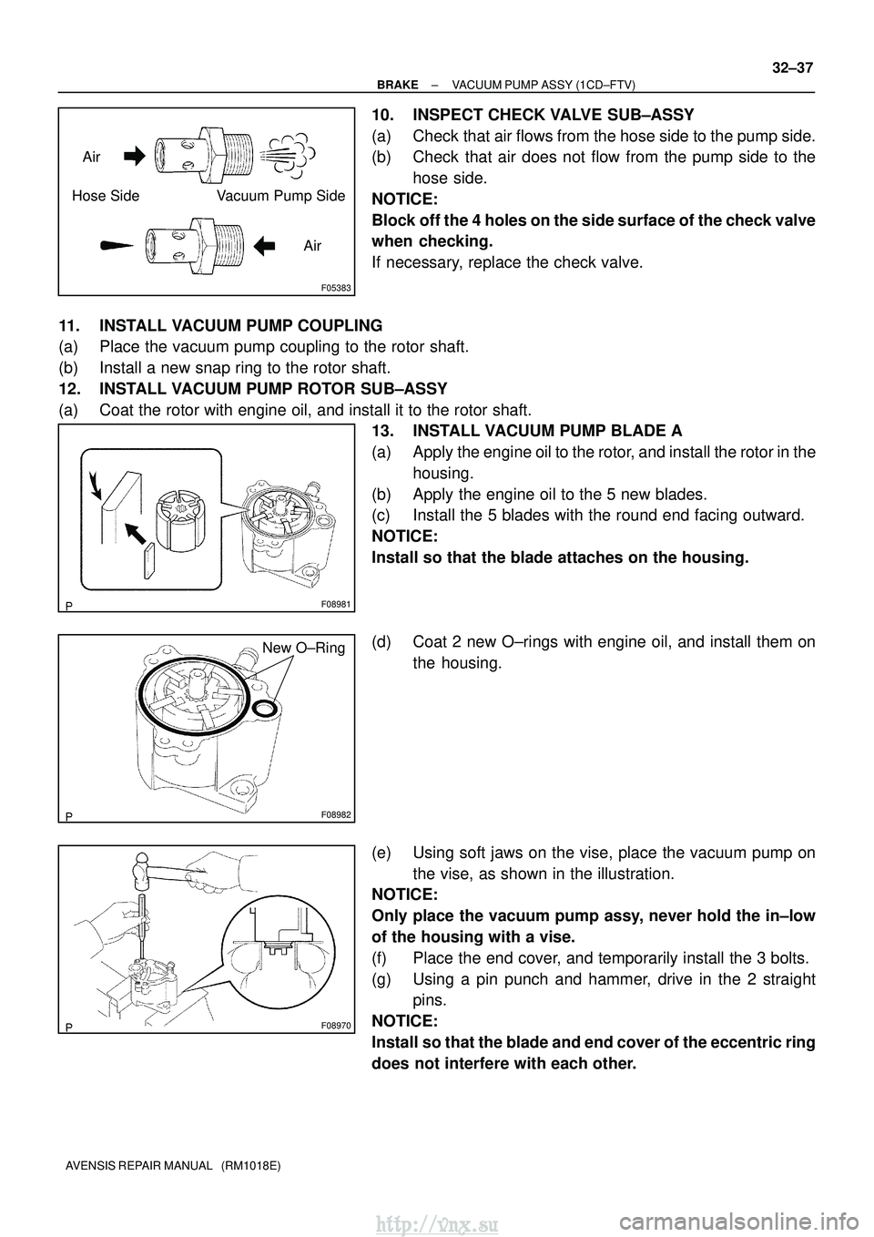
10. INSPECT CHECK VALVE SUB±ASSY
(a) Check that air flows from the hose side to the pump side.
(b) Check that air does not flow from the pump side to the
hose side.
NOTICE:
Block off the 4 holes on the side surface of the check valve
when checking.
If necessary, replace the check valve.
11. INSTALL VACUUM PUMP COUPLING
(a) Place the vacuum pump coupling to the rotor shaft.
(b) Install a new snap ring to the rotor shaft.
12. INSTALL VACUUM PUMP ROTOR SUB±ASSY
(a) Coat the rotor with engine oil, and install it to the rotor shaft. 13. INSTALL VACUUM PUMP BLADE A
(a) Apply the engine oil to the rotor, and install the rotor in the
housing.
(b) Apply the engine oil to the 5 new blades.
(c) Install the 5 blades with the round end facing outward.
NOTICE:
Install so that the blade attaches on the housing.
(d) Coat 2 new O±rings with engine oil, and install them on the housing.
(e) Using soft jaws on the vise, place the vacuum pump on the vise, as shown in the illustration.
NOTICE:
Only place the vacuum pump assy, never hold the in±low
of the housing with a vise.
(f) Place the end cover, and temporarily install the 3 bolts.
(g) Using a pin punch and hammer, drive in the 2 straight pins.
NOTICE:
Install so that the blade and end cover of the eccentric ring
does not interfere with each other.
http://vnx.su
Page 1133 of 2234
G24250
Vacuum HoseNew O±Ring
Oil Hose
F45366
Vacuum Gauge
±
BRAKE VACUUM PUMP ASSY (1CD±FTV)
32±39
AVENSIS REPAIR MANUAL (RM1018E)
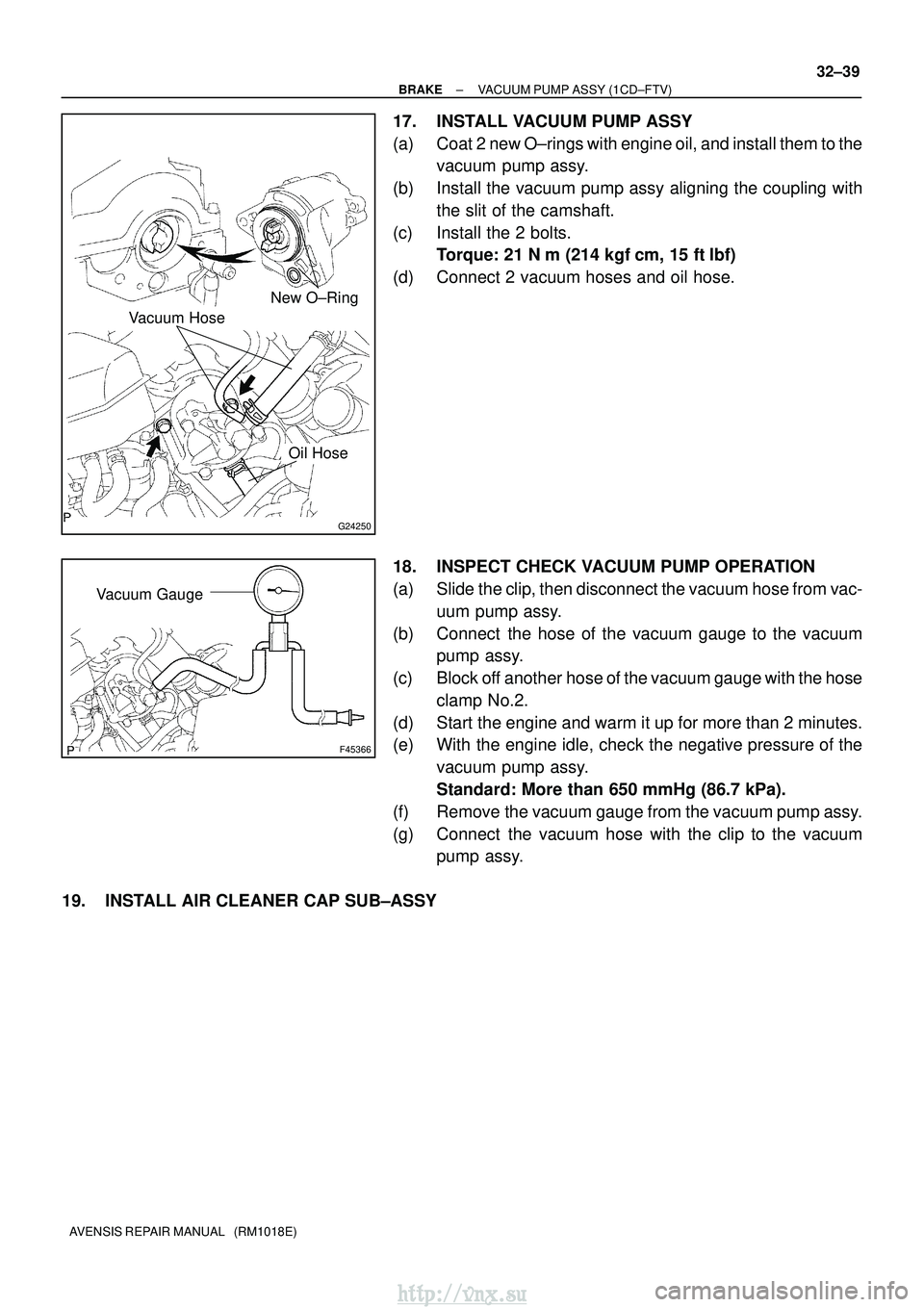
17. INSTALL VACUUM PUMP ASSY
(a) Coat 2 new O±rings with engine oil, and install them to the
vacuum pump assy.
(b) Install the vacuum pump assy aligning the coupling with the slit of the camshaft.
(c) Install the 2 bolts. Torque: 21 N �m (214 kgf� cm, 15 ft�lbf)
(d) Connect 2 vacuum hoses and oil hose.
18. INSPECT CHECK VACUUM PUMP OPERATION
(a) Slide the clip, then disconnect the vacuum hose from vac- uum pump assy.
(b) Connect the hose of the vacuum gauge to the vacuum pump assy.
(c) Block off another hose of the vacuum gauge with the hose clamp No.2.
(d) Start the engine and warm it up for more than 2 minutes.
(e) With the engine idle, check the negative pressure of the vacuum pump assy.
Standard: More than 650 mmHg (86.7 kPa).
(f) Remove the vacuum gauge from the vacuum pump assy.
(g) Connect the vacuum hose with the clip to the vacuum pump assy.
19. INSTALL AIR CLEANER CAP SUB±ASSY
http://vnx.su
Page 1172 of 2234
D30080
41±30
±
MANUAL TRANSMISSION/TRANSAXLE MANUAL TRANSAXLE ASSY (1AZ±FE/1AZ±FSE)
AVENSIS REPAIR MANUAL (RM1018E)
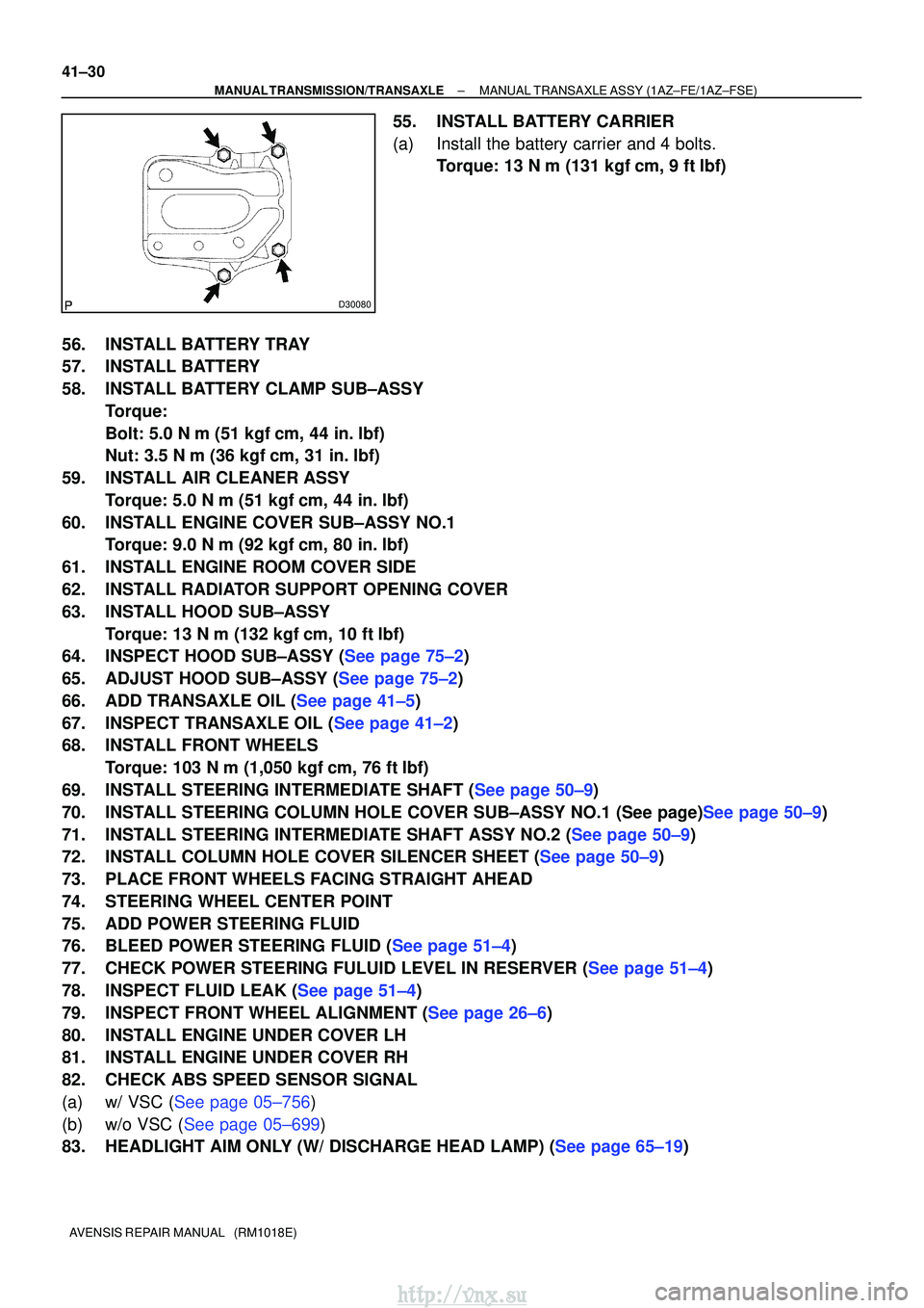
55. INSTALL BATTERY CARRIER
(a) Install the battery carrier and 4 bolts. Torque: 13 N �m (131 kgf� cm, 9 ft�lbf)
56. INSTALL BATTERY TRAY
57. INSTALL BATTERY
58. INSTALL BATTERY CLAMP SUB±ASSY Torque:
Bolt: 5.0 N �m (51 kgf �cm, 44 in. �lbf)
Nut: 3.5 N� m (36 kgf�cm, 31 in. �lbf)
59. INSTALL AIR CLEANER ASSY Torque: 5.0 N �m (51 kgf �cm, 44 in. �lbf)
60. INSTALL ENGINE COVER SUB±ASSY NO.1 Torque: 9.0 N �m (92 kgf �cm, 80 in. �lbf)
61. INSTALL ENGINE ROOM COVER SIDE
62. INSTALL RADIATOR SUPPORT OPENING COVER
63. INSTALL HOOD SUB±ASSY Torque: 13 N �m (132 kgf� cm, 10 ft�lbf)
64.INSPECT HOOD SUB±ASSY (See page 75±2)
65.ADJUST HOOD SUB±ASSY (See page 75±2)
66.ADD TRANSAXLE OIL (See page 41±5)
67.INSPECT TRANSAXLE OIL (See page 41±2)
68. INSTALL FRONT WHEELS
Torque: 103 N� m (1,050 kgf�cm, 76 ft �lbf)
69.INSTALL STEERING INTERMEDIATE SHAFT (See page 50±9)
70.INSTALL STEERING COLUMN HOLE COVER SUB±ASSY NO.1 (See page)See page 50±9)
71.INSTALL STEERING INTERMEDIATE SHAFT ASSY NO.2 (See page 50±9)
72.INSTALL COLUMN HOLE COVER SILENCER SHEET (See page 50±9)
73. PLACE FRONT WHEELS FACING STRAIGHT AHEAD
74. STEERING WHEEL CENTER POINT
75. ADD POWER STEERING FLUID
76.BLEED POWER STEERING FLUID (See page 51±4)
77.CHECK POWER STEERING FULUID LEVEL IN RESERVER (See page 51±4)
78.INSPECT FLUID LEAK (See page 51±4)
79.INSPECT FRONT WHEEL ALIGNMENT (See page 26±6)
80. INSTALL ENGINE UNDER COVER LH
81. INSTALL ENGINE UNDER COVER RH
82. CHECK ABS SPEED SENSOR SIGNAL
(a)w/ VSC (See page 05±756)
(b)w/o VSC (See page 05±699)
83.HEADLIGHT AIM ONLY (W/ DISCHARGE HEAD LAMP) (See page 65±19)
http://vnx.su
Page 1182 of 2234
41±40
±
MANUAL TRANSMISSION/TRANSAXLE MANUAL TRANSAXLE ASSY (1CD±FTV)
AVENSIS REPAIR MANUAL (RM1018E)
75. INSTALL HOOD SUB±ASSY Torque: 13 N �m (133 kgf� cm, 10 ft�lbf)
76.INSPECT HOOD SUB±ASSY (See page 75±2)
77.ADJUST HOOD SUB±ASSY (See page 75±2)
78.ADD TRANSAXLE OIL (See page 41±5)
79.INSPECT TRANSAXLE OIL (See page 41±2)
80. ADD POWER STEERING FLUID
81.BLEED POWER STEERING FLUID (See page 51±4)
82.CHECK POWER STEERING FULUID LEVEL IN RESERVER (See page 51±4)
83.INSPECT FLUID LEAK (See page 51±4)
84. INSTALL FRONT WHEELS Torque: 103 N� m (1,050 kgf�cm, 76 ft �lbf)
85.INSPECT FRONT WHEEL ALIGNMENT (See page 26±6)
86. INSTALL ENGINE UNDER COVER RH
87. INSTALL ENGINE UNDER COVER LH
88. CHECK ABS SPEED SENSOR SIGNAL
(a)w/ VSC (See page 05±756)
(b)w/o VSC (See page 05±699)
89.HEADLIGHT AIM ONLY (W/ DISCHARGE HEAD LAMP) (See page 65±19)
http://vnx.su
Page 1196 of 2234
4200D±04
D30053
LHD Steering Position Type:Pedal Height Adjust Point
Push Rod
Play and
Free Play
Adjust
Point Push Rod
Play
Pedal Height
RHD Steering Position Type: Push Rod Play and
Free Play Adjust Point
Pedal Height
Adjust Point
Push Rod
Play
Pedal Height
42±2
±
CLUTCH CLUTCH PEDAL SUB±ASSY (MTM)
AVENSIS REPAIR MANUAL (RM1018E)
CLUTCH PEDAL SUB±ASSY (MTM)
ADJUSTMENT
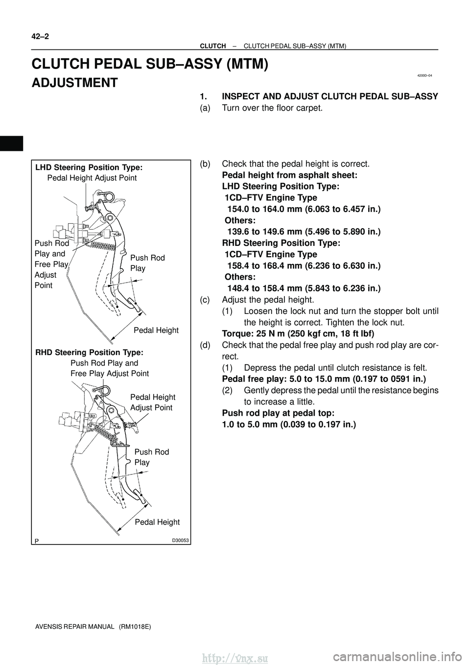
1. INSPECT AND ADJUST CLUTCH PEDAL SUB±ASSY
(a) Turn over the floor carpet.
(b) Check that the pedal height is correct. Pedal height from asphalt sheet:
LHD Steering Position Type:
1CD±FTV Engine Type
154.0 to 164.0 mm (6.063 to 6.457 in.)
Others:
139.6 to 149.6 mm (5.496 to 5.890 in.)
RHD Steering Position Type:
1CD±FTV Engine Type
158.4 to 168.4 mm (6.236 to 6.630 in.)
Others:
148.4 to 158.4 mm (5.843 to 6.236 in.)
(c) Adjust the pedal height. (1) Loosen the lock nut and turn the stopper bolt untilthe height is correct. Tighten the lock nut.
Torque: 25 N �m (250 kgf� cm, 18 ft�lbf)
(d) Check that the pedal free play and push rod play are cor- rect.
(1) Depress the pedal until clutch resistance is felt.
Pedal free play: 5.0 to 15.0 mm (0.197 to 0591 in.)
(2) Gently depress the pedal until the resistance beginsto increase a little.
Push rod play at pedal top:
1.0 to 5.0 mm (0.039 to 0.197 in.)
http://vnx.su
Page 1197 of 2234
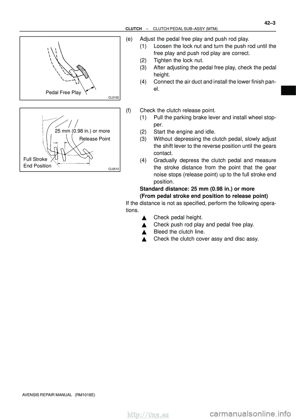
CL0102Pedal Free Play
CL0512
25 mm (0.98 in.) or moreRelease Point
Full Stroke
End Position
±
CLUTCH CLUTCH PEDAL SUB±ASSY (MTM)
42±3
AVENSIS REPAIR MANUAL (RM1018E)
(e) Adjust the pedal free play and push rod play.
(1) Loosen the lock nut and turn the push rod until thefree play and push rod play are correct.
(2) Tighten the lock nut.
(3) After adjusting the pedal free play, check the pedal height.
(4) Connect the air duct and install the lower finish pan-
el.
(f) Check the clutch release point. (1) Pull the parking brake lever and install wheel stop-
per.
(2) Start the engine and idle.
(3) Without depressing the clutch pedal, slowly adjust the shift lever to the reverse position until the gears
contact.
(4) Gradually depress the clutch pedal and measure the stroke distance from the point that the gear
noise stops (release point) up to the full stroke end
position.
Standard distance: 25 mm (0.98 in.) or more
(From pedal stroke end position to release point)
If the distance is not as specified, perform the following opera-
tions.
�Check pedal height.
�Check push rod play and pedal free play.
�Bleed the clutch line.
�Check the clutch cover assy and disc assy.
http://vnx.su
Page 1210 of 2234
D30814
D30487
SST(s)
1ZZ±FE/3ZZ±FE Engine Type:
1AZ±FE/1AZ±FSE Engine Type:SST(s)
42±20
±
CLUTCH CLUTCH RELEASE CYLINDER ASSY (MTM)
AVENSIS REPAIR MANUAL (RM1018E)
13. INSTALL CLUTCH ACCUMULATOR ASSY (1CD±FTV ENGINE TYPE)
(a) Install the clutch accumulator assy with the 2 nuts and
bolt.
Torque: 12 N� m (120 kgf�cm, 9 ft�lbf)
(b) Using SST(s), connect the 2 flexible hose tubes. SST 09023±00100
Torque: 15 N �m (155 kgf� cm, 11 ft�lbf)
(c) Connect the wire harness clamp.
14. CONNECT CLUTCH RELEASE CYLINDER TO FLEXIBLE HOSE TUBE (EXCEPT 1CD±FTV ENGINE
TYPE)
(a) Using SST(s), connect the flexible hose tube. SST 09023±00100
Torque: 15 N �m (155 kgf� cm, 11 ft�lbf)
15.INSTALL AIR TUBE NO.1 (1CD±FTV ENGINE TYPE) (See page 14±286)
16. INSTALL BATTERY (1CD±FTV ENGINE TYPE)
17. BLEED CLUTCH PIPE LINE
(a) Fill the brake reservoir tank with the brake fluid and bleed clutch syst\
em. Torque: 8.3 N �m (85 kgf �cm, 73 in. �lbf)
18. CHECK CLUTCH FLUID LEAKAGE
http://vnx.su
Page 1211 of 2234
4200B±04
±
CLUTCH CLUTCH SYSTEM (MTM)
42±1
AVENSIS REPAIR MANUAL (RM1018E)
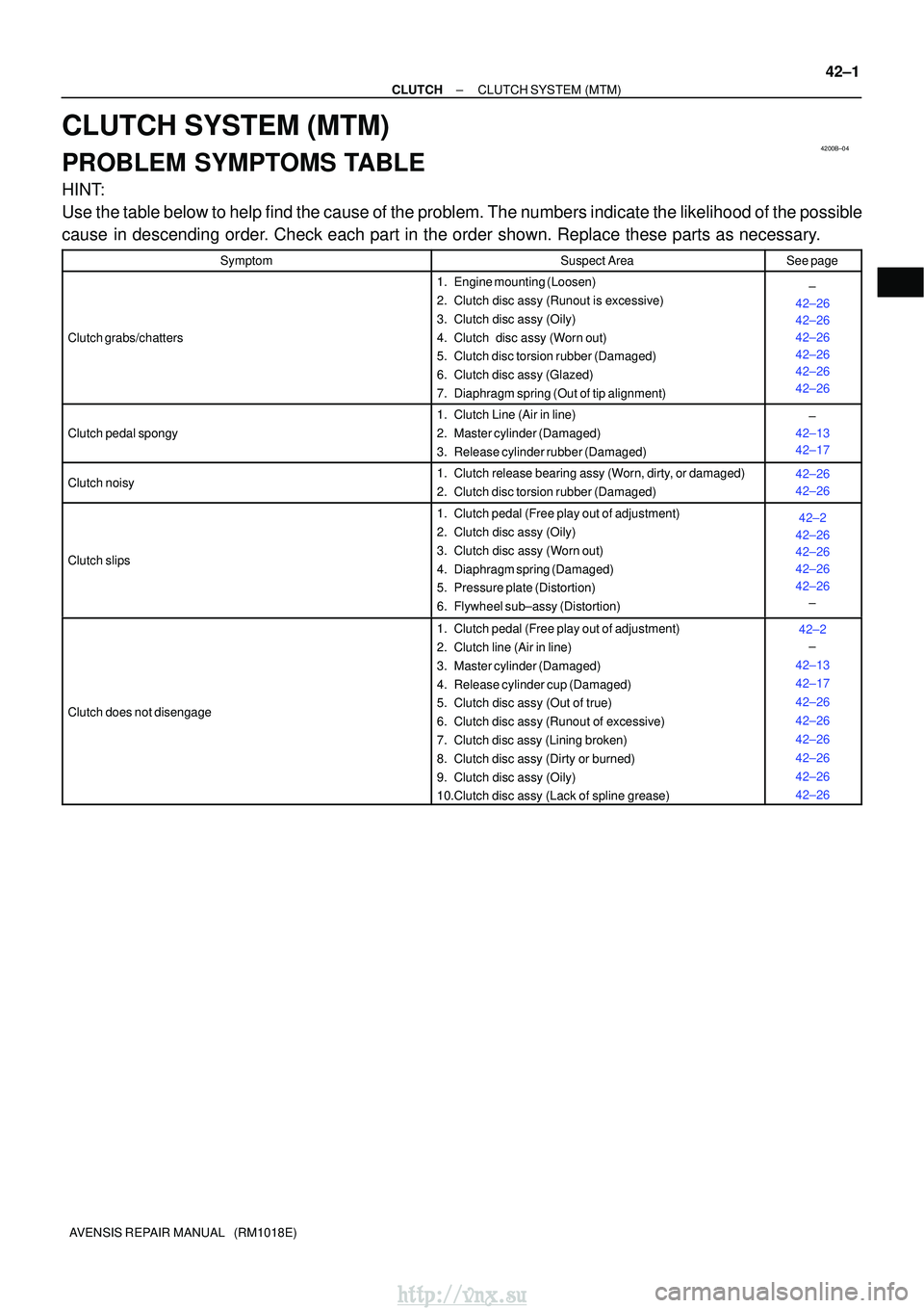
CLUTCH SYSTEM (MTM)
PROBLEM SYMPTOMS TABLE
HINT:
Use the table below to help find the cause of the problem. The numbers indi\
cate the likelihood of the possible
cause in descending order. Check each part in the order shown. Replace these parts as necessary.
SymptomSuspect AreaSee page
Clutch grabs/chatters
1. Engine mounting (Loosen)
2. Clutch disc assy (Runout is excessive)
3. Clutch disc assy (Oily)
4. Clutch disc assy (Worn out)
5. Clutch disc torsion rubber (Damaged)
6. Clutch disc assy (Glazed)
7. Diaphragm spring (Out of tip alignment)±
42±26
42±26
42±26
42±26
42±26
42±26
Clutch pedal spongy
1. Clutch Line (Air in line)
2. Master cylinder (Damaged)
3. Release cylinder rubber (Damaged)±
42±13
42±17
Clutch noisy1. Clutch release bearing assy (Worn, dirty, or damaged)
2. Clutch disc torsion rubber (Damaged)42±26
42±26
Clutch slips
1. Clutch pedal (Free play out of adjustment)
2. Clutch disc assy (Oily)
3. Clutch disc assy (Worn out)
4. Diaphragm spring (Damaged)
5. Pressure plate (Distortion)
6. Flywheel sub±assy (Distortion)42±2
42±26
42±26
42±26
42±26 ±
Clutch does not disengage
1. Clutch pedal (Free play out of adjustment)
2. Clutch line (Air in line)
3. Master cylinder (Damaged)
4. Release cylinder cup (Damaged)
5. Clutch disc assy (Out of true)
6. Clutch disc assy (Runout of excessive)
7. Clutch disc assy (Lining broken)
8. Clutch disc assy (Dirty or burned)
9. Clutch disc assy (Oily)
10.Clutch disc assy (Lack of spline grease)42±2
±
42±13
42±17
42±26
42±26
42±26
42±26
42±26
42±26
http://vnx.su