Page 1082 of 2234
F45161
Brake Master
Cylinder Sub±assyClutch Master Cylinder AssyM/T Transaxle:
Vacuum Tank
Diesel Engine Type:
Brake Fulid Level
Switch Connector
Accelerator Control
Cable Support
20 (204, 15)
19 (194, 14)
Clutch Reservoir
Hose M/T Transaxle:
Brake Booster Assy
�
Brake Booster Gasket
Brake Master Cylinder
Clevis Clip
Clevis Pin
13 (130, 9)
15 (155, 11) *1
29 (296, 21) *2
15 (155, 11)
N
�m (kgf� cm, ft�lbf)
: Specified torque
5.4 (55, 48 in.� lbf)
8.3 (85, 73 in.�lbf)
Wave Washer
Check Valve Grommet
15 (155, 11)
5.4 (55, 48 in.� lbf)
*1 w/ ABS:
*2 w/ VSC:
32±24
±
BRAKE BRAKE BOOSTER ASSY (RHD)
AVENSIS REPAIR MANUAL (RM1018E)
http://vnx.su
Page 1086 of 2234
F40021
Wooden Block
C82119
C80809
C80805
32±28
±
BRAKE BRAKE BOOSTER ASSY (RHD)
AVENSIS REPAIR MANUAL (RM1018E)
(h) Hold the engine with a jack, putting a wooden block be- tween them.
(i) Remove the 3 bolts and separate the engine mounting bracket RH from the body.
(j) Gradually tilt the engine by lowering the jack to remove the brake booster assy.
(k) Remove the 4 nuts and clevis.
(l) Pull out the brake booster assy.
14. REMOVE BRAKE BOOSTER GASKET
(a) Pull out the brake booster gasket.
15. REMOVE CHECK VALVE
(a) Remove the check valve from the brake booster assy.
16. INSTALL CHECK VALVE
(a) Install the check valve and grommet to the brake booster assy.
17. INSTALL BRAKE BOOSTER GASKET
(a) Install a new brake booster gasket to the brake booster assy.
http://vnx.su
Page 1087 of 2234
C80805
C82119
C81275
C81274
F45367
±
BRAKE BRAKE BOOSTER ASSY (RHD)
32±29
AVENSIS REPAIR MANUAL (RM1018E)
18. INSTALL BRAKE BOOSTER ASSY
(a) Install the clevis to the booster push rod.
(b) Install the brake booster assy with the 4 nuts.
Torque: 13 N �m (130 kgf� cm, 9 ft�lbf)
(c) Connect the vacuum hose to the check valve.
(d) Install the engine mounting bracket RH to the body with the 3 bolts.
Torque: 52 N �m (530 kgf� cm, 39 ft�lbf)
(e) Install the bolt to the rear engine mounting bracket. Torque: 87 N �m (887 kgf� cm, 64 ft�lbf)
(f) Install the bolt and nut to the front engine mounting brack- et.
Torque: 52 N� m (530 kgf�cm, 39 ft�lbf)
(g) Install the 2 nuts to the engine mounting bracket RH. Torque: 52 N �m (530 kgf� cm, 39 ft�lbf)
(h) Install the engine under cover.
(i) Connect the vacuum hose to the brake booster assy.
(j) Gasoline engine type: Install the vacuum pipe with 2 bolts to the body.
Torque: 5.4 N �m (55 kgf �cm, 48 in. �lbf)
http://vnx.su
Page 1090 of 2234

32±32
±
BRAKE BRAKE BOOSTER ASSY (RHD)
AVENSIS REPAIR MANUAL (RM1018E)
26. INSTALL ENGINE COVER NO.1
27.INSTALL ENGINE ASSEMBLY WITH TRANSAXLE (1AZ±FSE ENGINE TYPE) (See page 14±204)
28.INSTALL CLUTCH MASTER CYLINDER ASSY (M/T TRANSAXLE) (See page 42±13) SST 09023±00100
29.INSTALL BRAKE MASTER CYLINDER SUB±ASSY (See page 32±13)
(a) w/o VSC: SST 09023±00100
(b) w/ VSC: SST 09023±38400
30.FILL RESERVOIR WITH BRAKE FLUID (See page 32±4)
31.BLEED MASTER CYLINDER (See page 32±4)
(a) w/o VSC: SST 09023±00100, 09023±00100
(b) w/ VSC: SST 09023±00100, 09023±00100
32.BLEED BRAKE LINE (See page 32±4)
33.CHECK AND ADJUST BRAKE PEDAL HEIGHT (See page 32±6)
34.CHECK PEDAL FREE PLAY (See page 32±6)
35.CHECK PEDAL RESERVE DISTANCE (See page 32±6)
36.BLEED CLUTCH PIPE LINE (M/T TRANSAXLE) (See page 42±13)
37.INSPECT AND ADJUST CLUTCH PEDAL SUB±ASSY (M/T TRANSAXLE) (See page 42±2)
38.CHECK FLUID LEVEL IN RESERVOIR (See page 32±4)
39. CHECK BRAKE FLUID LEAKAGE
40. CHECK CLUTCH FLUID LEAKAGE (M/T TRANSAXLE)
http://vnx.su
Page 1098 of 2234

G24225
32±16
±
BRAKE BRAKE MASTER CYLINDER SUB±ASSY
AVENSIS REPAIR MANUAL (RM1018E)
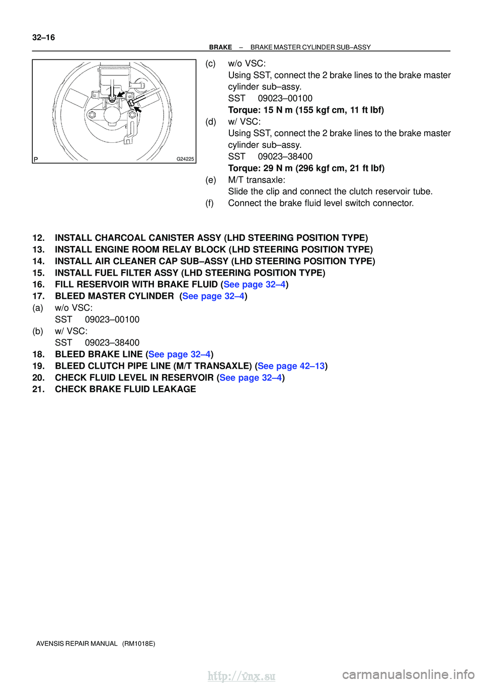
(c) w/o VSC: Using SST, connect the 2 brake lines to the brake master
cylinder sub±assy.
SST 09023±00100
Torque: 15 N �m (155 kgf� cm, 11 ft�lbf)
(d) w/ VSC: Using SST, connect the 2 brake lines to the brake master
cylinder sub±assy.
SST 09023±38400
Torque: 29 N �m (296 kgf� cm, 21 ft�lbf)
(e) M/T transaxle: Slide the clip and connect the clutch reservoir tube.
(f) Connect the brake fluid level switch connector.
12. INSTALL CHARCOAL CANISTER ASSY (LHD STEERING POSITION TYPE)
13. INSTALL ENGINE ROOM RELAY BLOCK (LHD STEERING POSITION TYPE)
14. INSTALL AIR CLEANER CAP SUB±ASSY (LHD STEERING POSITION TYPE)
15. INSTALL FUEL FILTER ASSY (LHD STEERING POSITION TYPE)
16.FILL RESERVOIR WITH BRAKE FLUID (See page 32±4)
17.BLEED MASTER CYLINDER (See page 32±4)
(a) w/o VSC: SST 09023±00100
(b) w/ VSC: SST 09023±38400
18.BLEED BRAKE LINE (See page 32±4)
19.BLEED CLUTCH PIPE LINE (M/T TRANSAXLE) (See page 42±13)
20.CHECK FLUID LEVEL IN RESERVOIR (See page 32±4)
21. CHECK BRAKE FLUID LEAKAGE
http://vnx.su
Page 1100 of 2234
G23176
Pedal Free Play
R00934
Pedal Reserve
Distance
±
BRAKE BRAKE PEDAL SUB±ASSY
32±7
AVENSIS REPAIR MANUAL (RM1018E)
(h) Check the protrusion of the rod.
Protrusion of the rod: 0.5 to 2.6 mm (0.020 to 0.102 in.)
(i) Install the clevis pin and clip.
(j) After adjusting the pedal height, check the pedal free
play.
2. CHECK PEDAL FREE PLAY
(a) Stop the engine and depress the brake pedal several times until there is no more vacuum left in the booster.
(b) Push in the pedal until the beginning of the resistance is felt. Measure the distance, as shown.
Pedal free play: 1 to 6 mm (0.04 to 0.24 in.)
3. CHECK PEDAL RESERVE DISTANCE
(a) Release the parking brake lever. With the engine running, depress the pedal and measure
the pedal reserve distance, as shown.
Pedal reserve distance from asphalt sheet at 490 N
(50 kgf, 110.2 lbf): More than 50 mm (1.97 in.)
If the distance is out of the specification , troubleshoot the brake
system.
http://vnx.su
Page 1127 of 2234
32091±05
F45366
Vacuum Gauge
±
BRAKE VACUUM PUMP ASSY (1CD±FTV)
32±33
AVENSIS REPAIR MANUAL (RM1018E)
VACUUM PUMP ASSY (1CD±FTV)
ON±VEHICLE INSPECTION
1. OPERATIONING CHECK
(a) Slide the clip, then disconnect the vacuum hose from vac-
uum pump assy.
(b) Connect the hose of the vacuum gauge to the vacuum pump assy.
(c) Block off another hose of the vacuum gauge with the hose clamp No.2.
(d) Start the engine and warm it up for more than 2 minutes.
(e) With the engine idle, check the negative pressure of the vacuum pump assy.
Standard: More than 650 mmHg (86.7 kPa).
(f) Remove the vacuum gauge from the vacuum pump assy.
(g) Connect the vacuum hose with the clip to the vacuum pump assy.
http://vnx.su
Page 1129 of 2234

320W2±01
G24251
Vacuum Hose
Oil Hose
F45364
F08966
F08967
±
BRAKE VACUUM PUMP ASSY (1CD±FTV)
32±35
AVENSIS REPAIR MANUAL (RM1018E)
OVERHAUL
1. REMOVE AIR CLEANER CAP SUB±ASSY
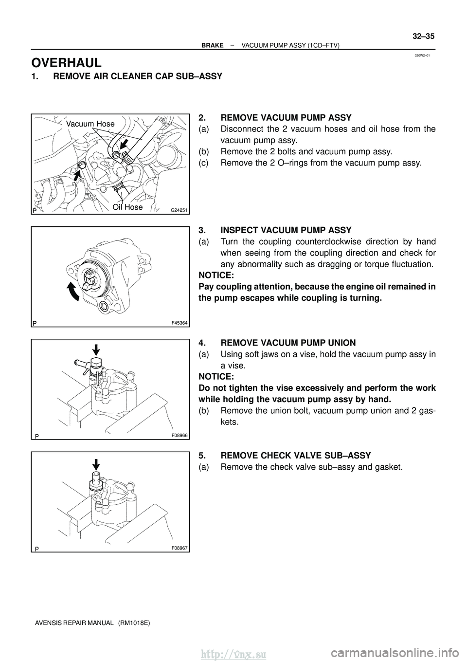
2. REMOVE VACUUM PUMP ASSY
(a) Disconnect the 2 vacuum hoses and oil hose from thevacuum pump assy.
(b) Remove the 2 bolts and vacuum pump assy.
(c) Remove the 2 O±rings from the vacuum pump assy.
3. INSPECT VACUUM PUMP ASSY
(a) Turn the coupling counterclockwise direction by hand when seeing from the coupling direction and check for
any abnormality such as dragging or torque fluctuation.
NOTICE:
Pay coupling attention, because the engine oil remained in
the pump escapes while coupling is turning.
4. REMOVE VACUUM PUMP UNION
(a) Using soft jaws on a vise, hold the vacuum pump assy in
a vise.
NOTICE:
Do not tighten the vise excessively and perform the work
while holding the vacuum pump assy by hand.
(b) Remove the union bolt, vacuum pump union and 2 gas-
kets.
5. REMOVE CHECK VALVE SUB±ASSY
(a) Remove the check valve sub±assy and gasket.
http://vnx.su