Page 1216 of 2234
C62956
D30058
1CD±FTV Engine Type:Others:
Transaxle Side
������
D25281
AB
C62958
±
CLUTCH CLUTCH UNIT (MTM)
42±27
AVENSIS REPAIR MANUAL (RM1018E)
8. REMOVE CLUTCH DISC ASSY
NOTICE:
Keep the lining part of the clutch disc assy, the pressure plate and surface of the flywheel sub±assy
away from oil and foreign attachment.
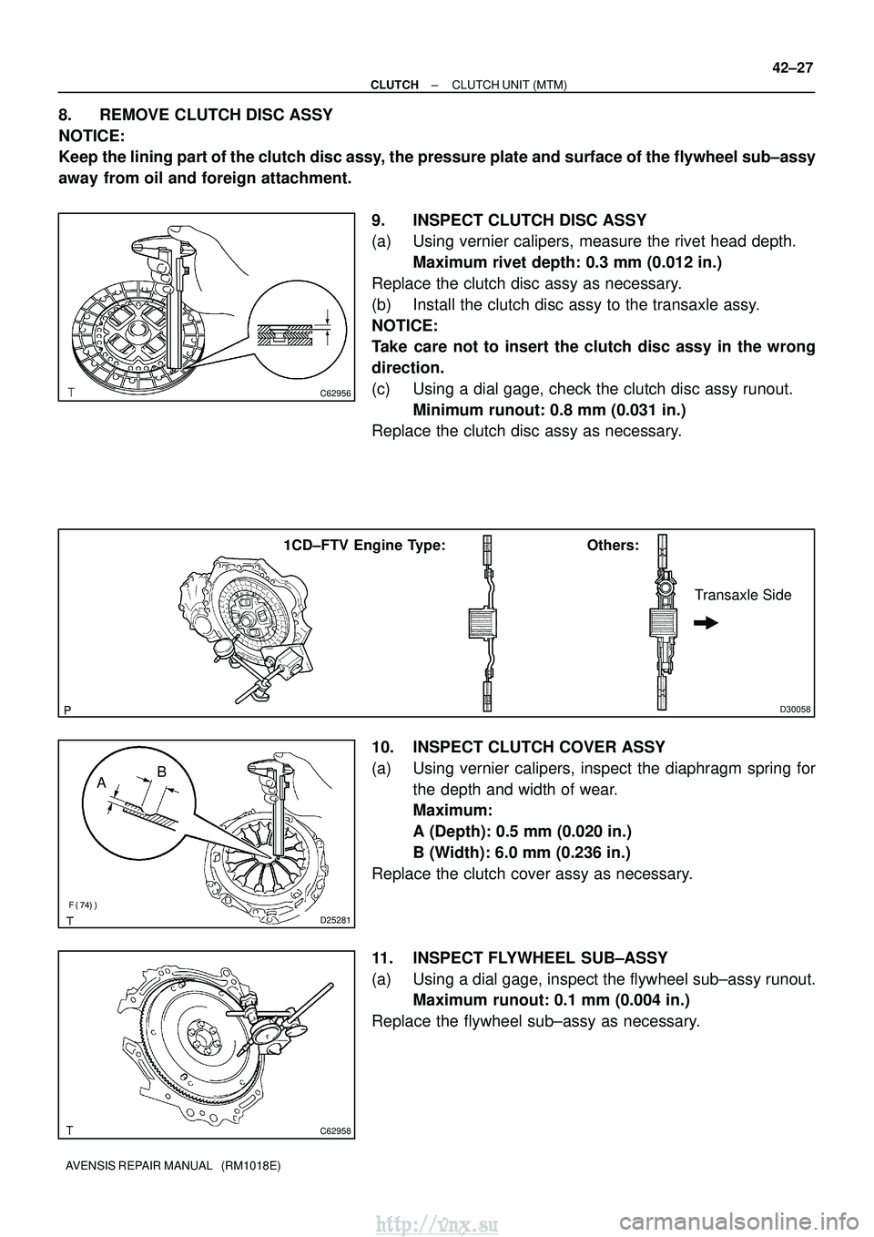
9. INSPECT CLUTCH DISC ASSY
(a) Using vernier calipers, measure the rivet head depth.Maximum rivet depth: 0.3 mm (0.012 in.)
Replace the clutch disc assy as necessary.
(b) Install the clutch disc assy to the transaxle assy.
NOTICE:
Take care not to insert the clutch disc assy in the wrong
direction.
(c) Using a dial gage, check the clutch disc assy runout. Minimum runout: 0.8 mm (0.031 in.)
Replace the clutch disc assy as necessary.
10. INSPECT CLUTCH COVER ASSY
(a) Using vernier calipers, inspect the diaphragm spring for
the depth and width of wear.
Maximum:
A (Depth): 0.5 mm (0.020 in.)
B (Width): 6.0 mm (0.236 in.)
Replace the clutch cover assy as necessary.
11. INSPECT FLYWHEEL SUB±ASSY
(a) Using a dial gage, inspect the flywheel sub±assy runout. Maximum runout: 0.1 mm (0.004 in.)
Replace the flywheel sub±assy as necessary.
http://vnx.su
Page 1217 of 2234
Q01060
D30059
1CD±FTV Engine Type:Others:
Flywheel Side
SST(s)
D26323
SST(s)
Matchmarks
7
1 (Temporally), 4
3
6
2.5 8
D00205
SST(s)
42±28
±
CLUTCH CLUTCH UNIT (MTM)
AVENSIS REPAIR MANUAL (RM1018E)
12. INSPECT CLUTCH RELEASE BEARING ASSY
(a) Turn the release bearing by hand while applying force in the axial direction.
HINT:
The bearing is permanently lubricated and requires no cleaning
or lubrication.
Replace the release bearing assy as necessary.
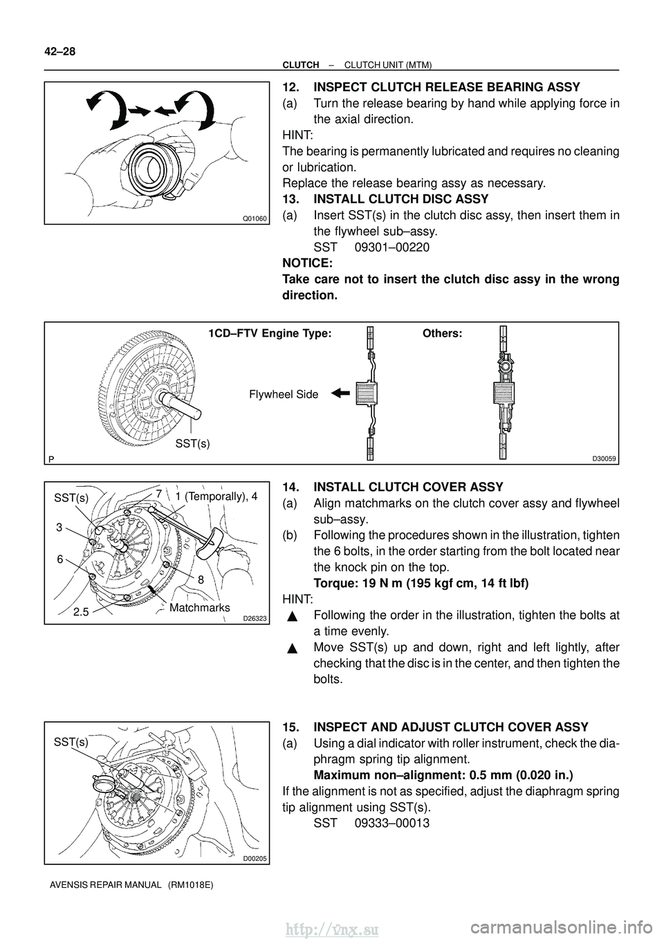
13. INSTALL CLUTCH DISC ASSY
(a) Insert SST(s) in the clutch disc assy, then insert them in the flywheel sub±assy.
SST 09301±00220
NOTICE:
Take care not to insert the clutch disc assy in the wrong
direction.
14. INSTALL CLUTCH COVER ASSY
(a) Align matchmarks on the clutch cover assy and flywheel
sub±assy.
(b) Following the procedures shown in the illustration, tighten
the 6 bolts, in the order starting from the bolt located near
the knock pin on the top.
Torque: 19 N �m (195 kgf� cm, 14 ft�lbf)
HINT:
�Following the order in the illustration, tighten the bolts at
a time evenly.
�Move SST(s) up and down, right and left lightly, after
checking that the disc is in the center, and then tighten the
bolts.
15. INSPECT AND ADJUST CLUTCH COVER ASSY
(a) Using a dial indicator with roller instrument, check the dia- phragm spring tip alignment.
Maximum non±alignment: 0.5 mm (0.020 in.)
If the alignment is not as specified, adjust the diaphragm spring
tip alignment using SST(s). SST 09333±00013
http://vnx.su
Page 1218 of 2234
D26819
EXCEPT 1CD±FTV Engine Type:
1CD±FTV Engine Type:
Release Hub Grease
±
CLUTCH CLUTCH UNIT (MTM)
42±29
AVENSIS REPAIR MANUAL (RM1018E)
16. INSTALL RELEASE FORK SUPPORT
(a) Install the release fork support to the transaxle assy.
Torque:
1ZZ±FE/3ZZ±FE/1CD±FTV Engine Type: 37 N� m (375 kgf�cm, 27 ft�lbf)
1AZ±FSE/1AZ±FE Engine Type: 47 N �m (480 kgf� cm, 35 ft�lbf)
17. INSTALL RELEASE BEARING HUB CLIP
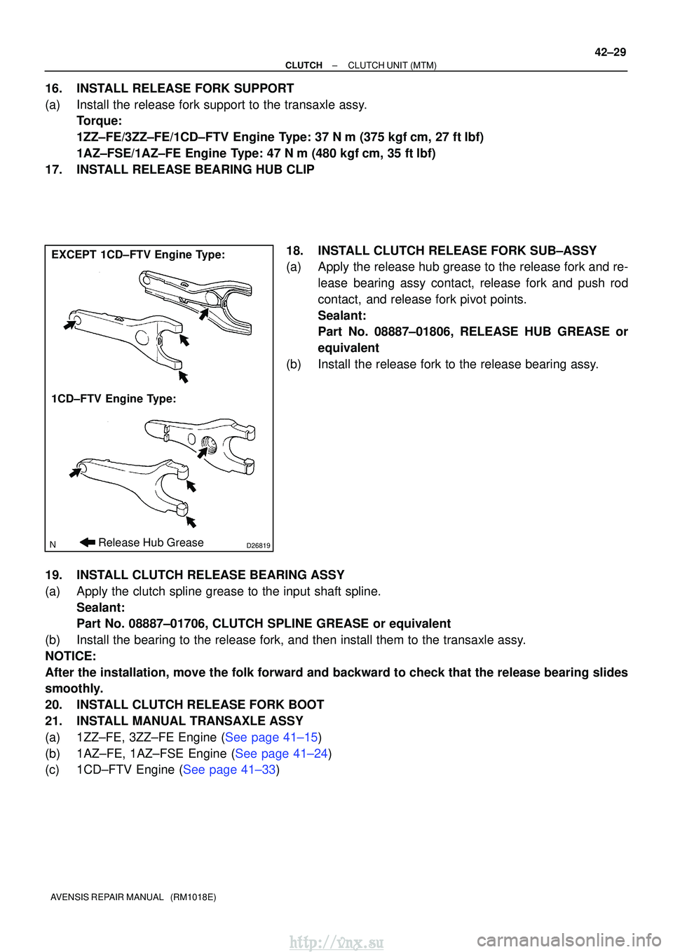
18. INSTALL CLUTCH RELEASE FORK SUB±ASSY
(a) Apply the release hub grease to the release fork and re-lease bearing assy contact, release fork and push rod
contact, and release fork pivot points.
Sealant:
Part No. 08887±01806, RELEASE HUB GREASE or
equivalent
(b) Install the release fork to the release bearing assy.
19. INSTALL CLUTCH RELEASE BEARING ASSY
(a) Apply the clutch spline grease to the input shaft spline. Sealant:
Part No. 08887±01706, CLUTCH SPLINE GREASE or equivalent
(b) Install the bearing to the release fork, and then install them to the tr\
ansaxle assy.
NOTICE:
After the installation, move the folk forward and backward to check that\
the release bearing slides
smoothly.
20. INSTALL CLUTCH RELEASE FORK BOOT
21. INSTALL MANUAL TRANSAXLE ASSY
(a)1ZZ±FE, 3ZZ±FE Engine (See page 41±15)
(b)1AZ±FE, 1AZ±FSE Engine (See page 41±24)
(c)1CD±FTV Engine (See page 41±33)
http://vnx.su
Page 1244 of 2234
510DE±02
F40449
R11229
NormalAbnormal
R00427
51±4
±
POWER STEERING POWER STEERING SYSTEM
AVENSIS REPAIR MANUAL (RM1018E)
ON±VEHICLE INSPECTION
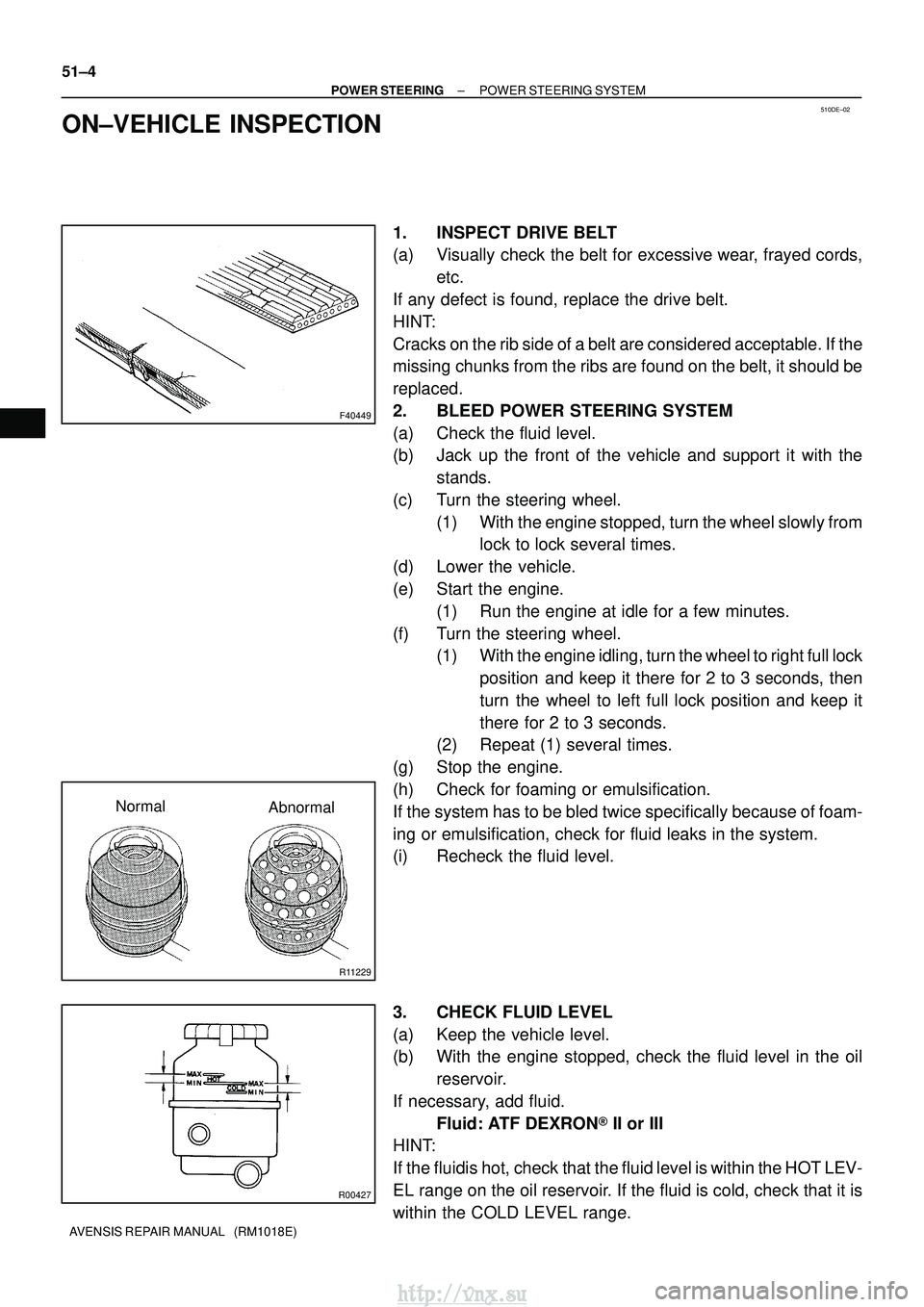
1. INSPECT DRIVE BELT
(a) Visually check the belt for excessive wear, frayed cords, etc.
If any defect is found, replace the drive belt.
HINT:
Cracks on the rib side of a belt are considered acceptable. If the
missing chunks from the ribs are found on the belt, it should be
replaced.
2. BLEED POWER STEERING SYSTEM
(a) Check the fluid level.
(b) Jack up the front of the vehicle and support it with the stands.
(c) Turn the steering wheel. (1) With the engine stopped, turn the wheel slowly fromlock to lock several times.
(d) Lower the vehicle.
(e) Start the engine. (1) Run the engine at idle for a few minutes.
(f) Turn the steering wheel. (1) With the engine idling, turn the wheel to right full lock
position and keep it there for 2 to 3 seconds, then
turn the wheel to left full lock position and keep it
there for 2 to 3 seconds.
(2) Repeat (1) several times.
(g) Stop the engine.
(h) Check for foaming or emulsification.
If the system has to be bled twice specifically because of foam-
ing or emulsification, check for fluid leaks in the system.
(i) Recheck the fluid level.
3. CHECK FLUID LEVEL
(a) Keep the vehicle level.
(b) With the engine stopped, check the fluid level in the oil reservoir.
If necessary, add fluid. Fluid: ATF DEXRON� II or III
HINT:
If the fluidis hot, check that the fluid level is within the HOT LEV-
EL range on the oil reservoir. If the fluid is cold, check that it is
within the COLD LEVEL range.
http://vnx.su
Page 1245 of 2234
R11229
NormalAbnormal
R11786Engine Idling Engine Stopped5 mm (0.20 in.)
or less
±
POWER STEERING POWER STEERING SYSTEM
51±5
AVENSIS REPAIR MANUAL (RM1018E)
(c) Start the engine and run it at idle.
(d) Turn the steering wheel from lock to lock several times to
boost fluid temperature.
Fluid temperature: 80� C (176�F)
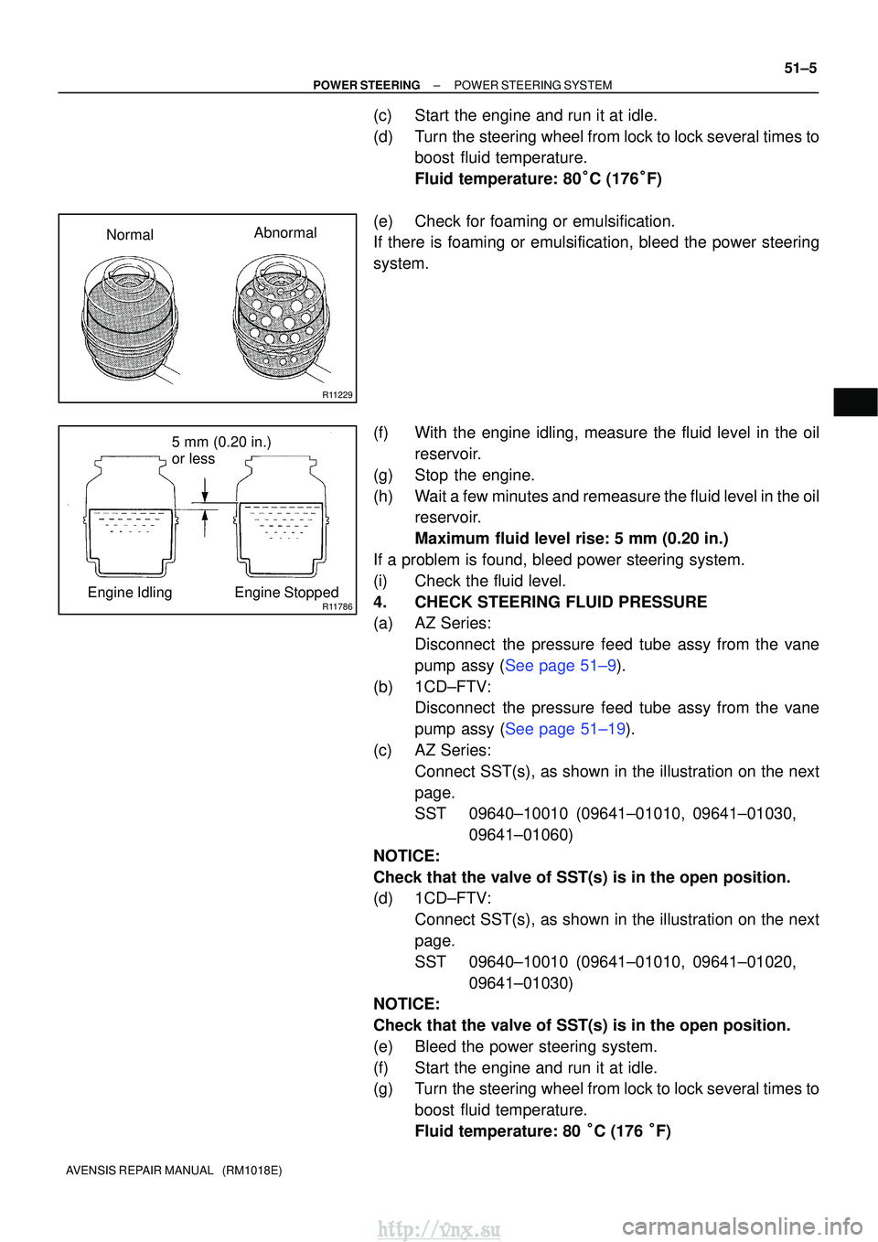
(e) Check for foaming or emulsification.
If there is foaming or emulsification, bleed the power steering
system.
(f) With the engine idling, measure the fluid level in the oil reservoir.
(g) Stop the engine.
(h) Wait a few minutes and remeasure the fluid level in the oil reservoir.
Maximum fluid level rise: 5 mm (0.20 in.)
If a problem is found, bleed power steering system.
(i) Check the fluid level.
4. CHECK STEERING FLUID PRESSURE
(a) AZ Series: Disconnect the pressure feed tube assy from the vane
pump assy (See page 51±9).
(b) 1CD±FTV: Disconnect the pressure feed tube assy from the vane
pump assy (See page 51±19).
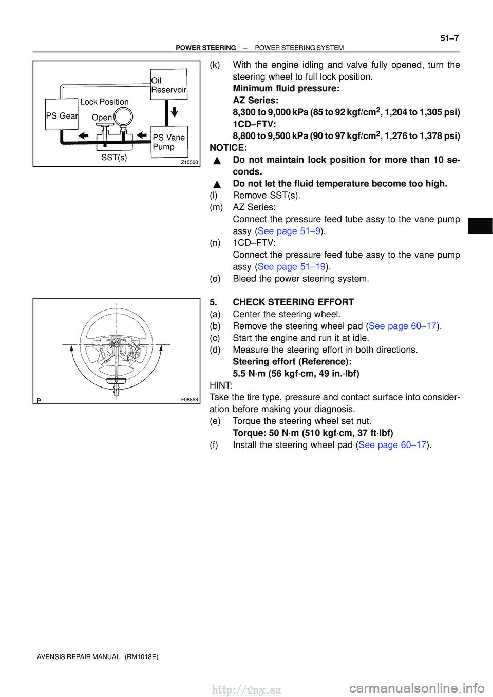
(c) AZ Series: Connect SST(s), as shown in the illustration on the next
page.
SST 09640±10010 (09641±01010, 09641±01030, 09641±01060)
NOTICE:
Check that the valve of SST(s) is in the open position.
(d) 1CD±FTV: Connect SST(s), as shown in the illustration on the next
page.
SST 09640±10010 (09641±01010, 09641±01020, 09641±01030)
NOTICE:
Check that the valve of SST(s) is in the open position.
(e) Bleed the power steering system.
(f) Start the engine and run it at idle.
(g) Turn the steering wheel from lock to lock several times to
boost fluid temperature.
Fluid temperature: 80 �C (176 �F)
http://vnx.su
Page 1247 of 2234
Z15500
Oil
ReservoirPS Vane
Pump
PS Gear
SST(s)
Open
Lock Position
F08858
±
POWER STEERING POWER STEERING SYSTEM
51±7
AVENSIS REPAIR MANUAL (RM1018E)
(k) With the engine idling and valve fully opened, turn the
steering wheel to full lock position.
Minimum fluid pressure:
AZ Series:
8,300 to 9,000 kPa (85 to 92 kgf/cm
2, 1,204 to 1,305 psi)
1CD±FTV:
8,800 to 9,500 kPa (90 to 97 kgf/cm
2, 1,276 to 1,378 psi)
NOTICE:
�Do not maintain lock position for more than 10 se-
conds.
�Do not let the fluid temperature become too high.
(l) Remove SST(s).
(m) AZ Series:
Connect the pressure feed tube assy to the vane pump
assy (See page 51±9).
(n) 1CD±FTV:
Connect the pressure feed tube assy to the vane pump
assy (See page 51±19).
(o) Bleed the power steering system.
5. CHECK STEERING EFFORT
(a) Center the steering wheel.
(b)Remove the steering wheel pad (See page 60±17).
(c) Start the engine and run it at idle.
(d) Measure the steering effort in both directions. Steering effort (Reference):
5.5 N´m (56 kgf´cm, 49 in.´lbf)
HINT:
Take the tire type, pressure and contact surface into consider-
ation before making your diagnosis.
(e) Torque the steering wheel set nut. Torque: 50 N´m (510 kgf´cm, 37 ft´lbf)
(f)Install the steering wheel pad (See page 60±17).
http://vnx.su
Page 1259 of 2234
������
������D30705
LHD:
A
B
RHD:
Matchmarks
Matchmarks
A
B
±
POWER STEERING RACK & PINION POWER STEERING GEAR ASSY
51±45
AVENSIS REPAIR MANUAL (RM1018E)
50. INSTALL HEIGHT CONTROL SENSOR SUB±ASSY FR RH (W/ DISCHARGE HEAD LAMP)
(See page 65±28)
51.INSTALL TIE ROD END SUB±ASSY LH (See page 30±6)
52. INSTALL TIE ROD END SUB±ASSY RH
HINT:
Perform the same procedure on the other side.
53. INSTALL FRONT WHEELS
Torque: 103 N� m (1,050 kgf�cm, 76 ft �lbf)
54. INSTALL STEERING COLUMN HOLE COVER SUB±ASSY NO.1
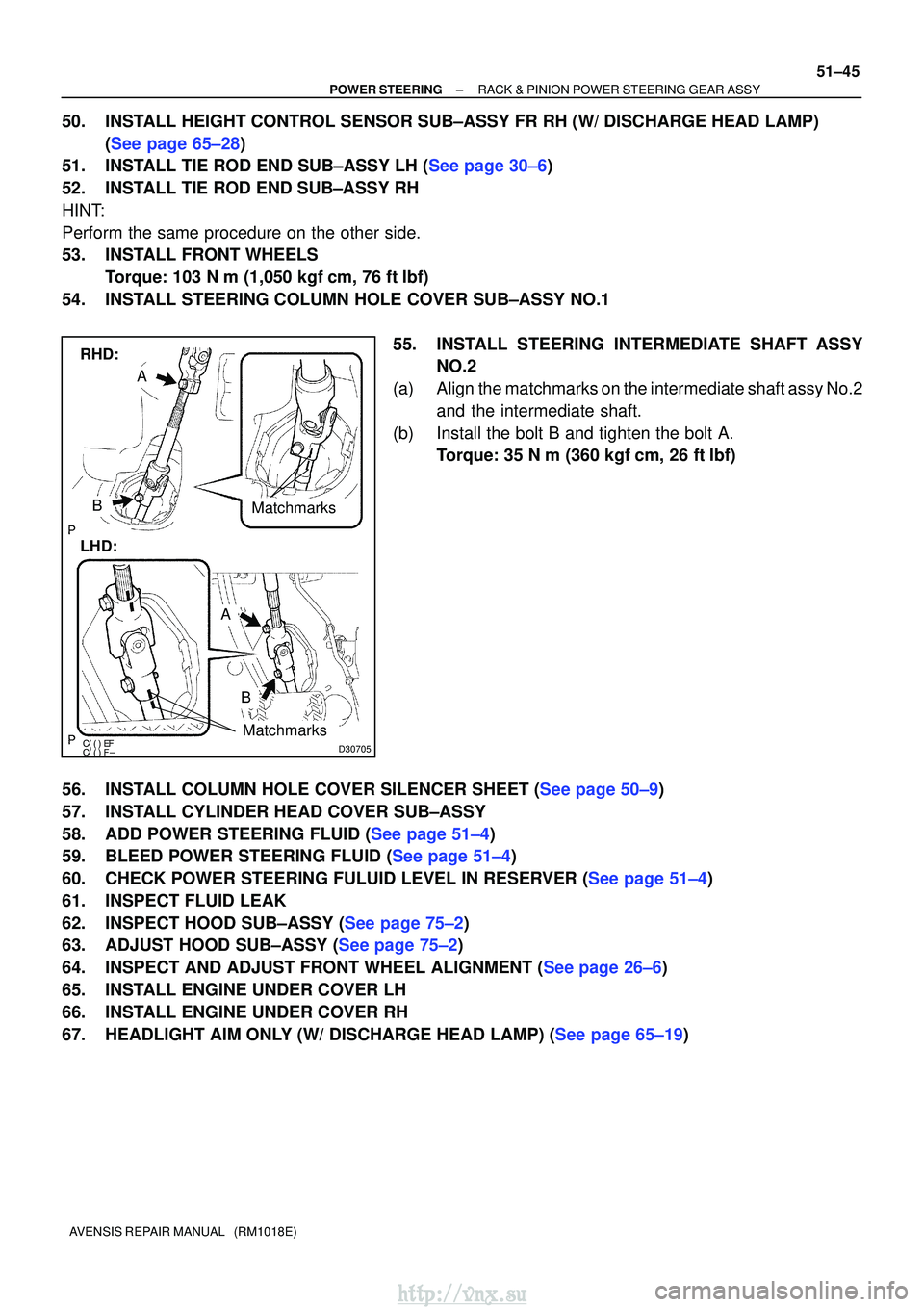
55. INSTALL STEERING INTERMEDIATE SHAFT ASSYNO.2
(a) Align the matchmarks on the intermediate shaft assy No.2 and the intermediate shaft.
(b) Install the bolt B and tighten the bolt A. Torque: 35 N �m (360 kgf� cm, 26 ft�lbf)
56.INSTALL COLUMN HOLE COVER SILENCER SHEET (See page 50±9)
57. INSTALL CYLINDER HEAD COVER SUB±ASSY
58.ADD POWER STEERING FLUID (See page 51±4)
59.BLEED POWER STEERING FLUID (See page 51±4)
60.CHECK POWER STEERING FULUID LEVEL IN RESERVER (See page 51±4)
61. INSPECT FLUID LEAK
62.INSPECT HOOD SUB±ASSY (See page 75±2)
63.ADJUST HOOD SUB±ASSY (See page 75±2)
64.INSPECT AND ADJUST FRONT WHEEL ALIGNMENT (See page 26±6)
65. INSTALL ENGINE UNDER COVER LH
66. INSTALL ENGINE UNDER COVER RH
67.HEADLIGHT AIM ONLY (W/ DISCHARGE HEAD LAMP) (See page 65±19)
http://vnx.su
Page 1285 of 2234
±
POWER STEERING VANE PUMP ASSY (AZ Series)
51±17
AVENSIS REPAIR MANUAL (RM1018E)
37. CONNECT OIL RESERVOIR TO PUMP HOSE NO.1
(a) Connect the oil reservoir to pump hose No.1 with the clip.
NOTICE:
Take care not to spill fluid on the V belt.
38. INSTALL FAN AND GENERATOR V BELT
1AZ±FE: (See page 14±105)
1AZ±FSE: (See page 14±185)
39. INSTALL ENGINE UNDER COVER RH
40. INSTALL FRONT WHEEL RH Torque: 103 N� m (1,050 kgf�cm, 76 ft �lbf)
41.ADD POWER STEERING FLUID (See page 51±4)
42.BLEED POWER STEERING FLUID (See page 51±4)
43.CHECK POWER STEERING FULUID LEVEL IN RESERVER (See page 51±4)
44. INSPECT FLUID LEAK
http://vnx.su