Page 1366 of 2234
550YX±01
I35991
PulleyWeight HubWeight Hub
±
HEATER & AIR CONDITIONER W/PULLEY COMPRESSOR ASSY (3ZZ±FE)
55±69
AVENSIS REPAIR MANUAL (RM1018E)
W/PULLEY COMPRESSOR ASSY (3ZZ±FE)
ON±VEHICLE INSPECTION
1. INSPECT W/PULLEY COMPRESSOR ASSY
(a) Check the operation.
(1) Start the engine.
(2) Inspect the weight hub.
Standard: The weight hub rotates along with the pulley
http://vnx.su
Page 1459 of 2234

±
SUPPLEMENTAL RESTRAINT SYSTEM SUPPLEMENTAL RESTRAINT SYSTEM
60±15
AVENSIS REPAIR MANUAL (RM1018E)
18. SIDE AIRBAG SENSOR ASSY (VEHICLE INVOLVED IN COLLISION AND AIRBAG IS NOT
DEPLOYED)
(a)Do a diagnostic system check (See page 05±1184).
(b) When the center pillar of the vehicle or its periphery is damaged, check if \
there is any damage to the
side airbag sensor. If there are any defects as mentioned below, replace the side airbag sensor with
a new one:
If there are any defects as mentioned below, replace the side airbag sensor with a new one:
�Cracks, dents or chips in the case.
�Cracks, dents, chips and scratches in the connector.
�Peeling off of the label or damage to the serial number.
19. SIDE AIRBAG SENSOR ASSY (VEHICLE INVOLVED IN COLLISION AND AIRBAG IS DEPLOYED)
(a)Replace the front seat airbag assy and side airbag sensor assy (See page 60±66).
20. AIRBAG SENSOR REAR (VEHICLE NOT INVOLVED IN COLLISION)
(a)Do a diagnostic system check (See page 05±1184).
21. AIRBAG SENSOR REAR (VEHICLE INVOLVED IN COLLISION AND AIRBAG IS NOT DEPLOYED)
(a)Do a diagnostic system check (See page 05±1184).
(b) When the quarter panel of the vehicle or its periphery is damaged, check if \
there is any damage to the airbag sensor rear. If there are any defects as mentioned below, replace the airbag sensor rear with
a new one:
If there are any defects as mentioned below, replace the airbag sensor rear with a new one:
�Cracks, dents or chips in the case.
�Cracks, dents, chips and scratches in the connector.
�Peeling off of the label or damage to the serial number.
22. AIRBAG SENSOR REAR (VEHICLE INVOLVED IN COLLISION AND AIRBAG IS DEPLOYED)
(a)Replace the curtain shield airbag assy and airbag sensor rear (See page 60±68).
23. SEAT POSITION AIRBAG SENSOR (VEHICLES NOT INVOLVED IN COLLISION)
(a)Do a diagnostic system check (See page 05±1184).
24. SEAT POSITION AIRBAG SENSOR (VEHICLE INVOLVED IN COLLISION)
(a)Do a diagnostic system check (See page 05±1184).
(b) Do a visual check for damage to the seat position airbag sensor even if th\
e airbag was not deployed:
�Cracks, dents or chips in the case.
�Cracks, dents, chips and scratches in the connector.
25. WIRE HARNESS AND CONNECTOR (VEHICLE NOT INVOLVED IN COLLISION)
(a)Do a diagnostic system check (See page 05±1184).
26. WIRE HARNESS AND CONNECTOR (VEHICLE INVOLVED IN COLLISION)
(a)Do a diagnostic system check (See page 05±1184).
(b) Check for breaks in all wires of the SRS wire harness, and exposed condu\
ctors.
(c) Check to see if the SRS wire harness connectors are cracked or chipped.
HINT:
The SRS wire harness is integrated with the engine room main wire, instrume\
nt panel wire floor wire, floor
wire No.2 harness assembly.
http://vnx.su
Page 1488 of 2234
650SY±01
I35230
±
LIGHTINGFOG LAMP ASSY LH
65±23
AVENSIS REPAIR MANUAL (RM1018E)
ADJUSTMENT
1.PUT VEHICLE THESE CONDITIONS
(a)Tire inflation pressure is within the specified value. (See page 28±1)
(b) Start the engine.
2. ADJUST FOG LIGHT AIM
(a) The fog light aim can be adjusted by turning the aimingscrew in the vertical direction.
HINT:
The optical aim moves upward when turning the screwdriver
clockwise and moves downward when turning the screwdriver
center clockwise.
3. CHECK FOG LIGHT AIM
http://vnx.su
Page 1496 of 2234

I35248
V LH Line
V RH Line
V Line90�
3 m (9.84 ft)
I37308
Low Beam:V LH Line
V RH Line
30mm
(1.18 in.) 84 mm
(3.3 in.)
H Line6mm
(0.23 in.)
I37102
High Beam:V LH Line
V RH Line
H Line
I35802Adjusting Bolt A
Adjusting Bolt B
65±20
±
LIGHTING HEADLAMP UNIT LH
AVENSIS REPAIR MANUAL (RM1018E)
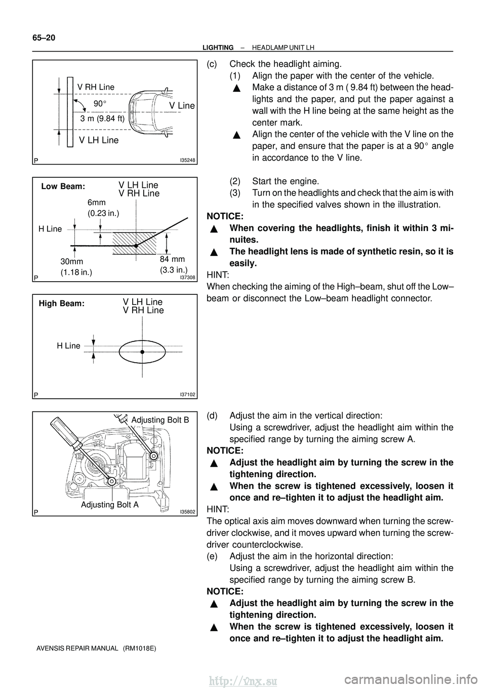
(c) Check the headlight aiming. (1) Align the paper with the center of the vehicle.
�Make a distance of 3 m ( 9.84 ft) between the head-
lights and the paper, and put the paper against a
wall with the H line being at the same height as the
center mark.
�Align the center of the vehicle with the V line on the
paper, and ensure that the paper is at a 90 � angle
in accordance to the V line.
(2) Start the engine.
(3) Turn on the headlights and check that the aim is with in the specified valves shown in the illustration.
NOTICE:
�When covering the headlights, finish it within 3 mi-
nuites.
�The headlight lens is made of synthetic resin, so it is
easily.
HINT:
When checking the aiming of the High±beam, shut off the Low±
beam or disconnect the Low±beam headlight connector.
(d) Adjust the aim in the vertical direction: Using a screwdriver, adjust the headlight aim within the
specified range by turning the aiming screw A.
NOTICE:
�Adjust the headlight aim by turning the screw in the
tightening direction.
�When the screw is tightened excessively, loosen it
once and re±tighten it to adjust the headlight aim.
HINT:
The optical axis aim moves downward when turning the screw-
driver clockwise, and it moves upward when turning the screw-
driver counterclockwise.
(e) Adjust the aim in the horizontal direction: Using a screwdriver, adjust the headlight aim within the
specified range by turning the aiming screw B.
NOTICE:
�Adjust the headlight aim by turning the screw in the
tightening direction.
�When the screw is tightened excessively, loosen it
once and re±tighten it to adjust the headlight aim.
http://vnx.su
Page 1506 of 2234

±
LIGHTING LIGHTING SYSTEM
65±7
AVENSIS REPAIR MANUAL (RM1018E)
(b) Connect the connector to the headlamp leveling ECU
assy, then turn the ignition switch ON and light control
switch into HEAD position. Inspect the wire harness side
connector from the back side as shown in the chart.
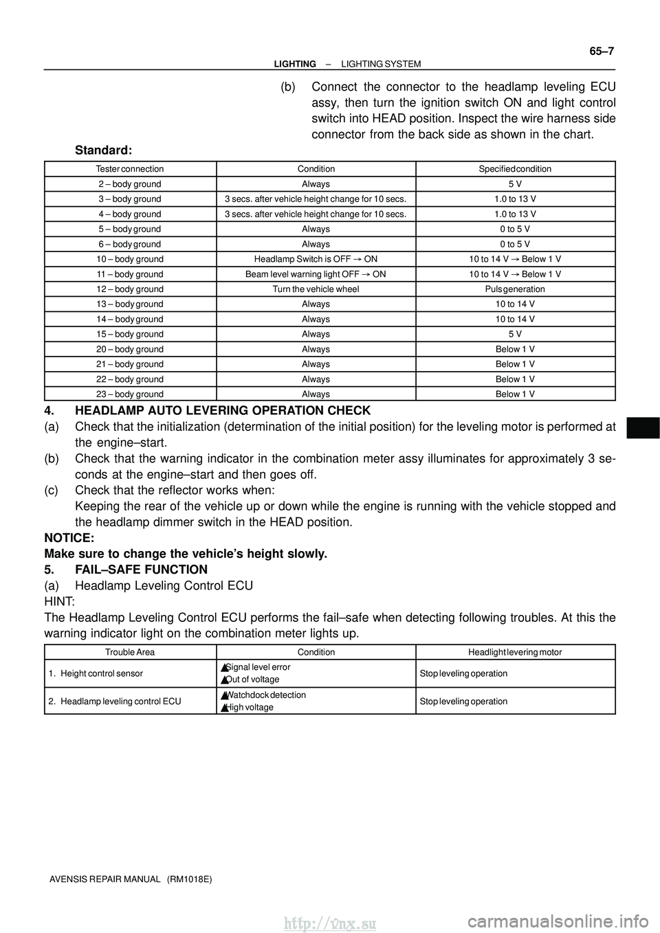
Standard:
Tester connectionConditionSpecified condition
2 ± body groundAlways5 V
3 ± body ground3 secs. after vehicle height change for 10 secs.1.0 to 13 V
4 ± body ground3 secs. after vehicle height change for 10 secs.1.0 to 13 V
5 ± body groundAlways0 to 5 V
6 ± body groundAlways0 to 5 V
10 ± body groundHeadlamp Switch is OFF � ON10 to 14 V � Below 1 V
11 ± body groundBeam level warning light OFF � ON10 to 14 V � Below 1 V
12 ± body groundTurn the vehicle wheelPuls generation
13 ± body groundAlways10 to 14 V
14 ± body groundAlways10 to 14 V
15 ± body groundAlways5 V
20 ± body groundAlwaysBelow 1 V
21 ± body groundAlwaysBelow 1 V
22 ± body groundAlwaysBelow 1 V
23 ± body groundAlwaysBelow 1 V
4. HEADLAMP AUTO LEVERING OPERATION CHECK
(a) Check that the initialization (determination of the initial position) for t\
he leveling motor is performed at
the engine±start.
(b) Check that the warning indicator in the combination meter assy illuminates for approximately 3 se- conds at the engine±start and then goes off.
(c) Check that the reflector works when:
Keeping the rear of the vehicle up or down while the engine is running with the vehicle stopped and
the headlamp dimmer switch in the HEAD position.
NOTICE:
Make sure to change the vehicle's height slowly.
5. FAIL±SAFE FUNCTION
(a) Headlamp Leveling Control ECU
HINT:
The Headlamp Leveling Control ECU performs the fail±safe when detecti\
ng following troubles. At this the
warning indicator light on the combination meter lights up.
Trouble AreaConditionHeadlight levering motor
1. Height control sensor� Signal level error
� Out of voltageStop leveling operation
2. Headlamp leveling control ECU�Watchdock detection
� High voltageStop leveling operation
http://vnx.su
Page 1523 of 2234
660CU±01
I35778
A: 150 mm (5.91 in.)
B: 50 mm (1.97 in.)
C: 480 mm (18.90 in.)
D: 295 mm (11.61 in.)
E: 310 mm (12.21 in.)F: 275 mm (10.83 in.)
G: 130 mm (5.12 in.)
H: 420 mm (16.54 in.)
I: 280 mm (11.02 in.)
Front:
AB
C
DE
FG
HI
A
A
A
B
B
B
C
66±22
±
WIPER & WASHER WASHER NOZZLE SUB±ASSY
AVENSIS REPAIR MANUAL (RM1018E)
WASHER NOZZLE SUB±ASSY
ADJUSTMENT
1. REMOVE WASHER NOZZLE SUB±ASSY
(a) With the engine running, check that the point where the washer fluid hits the windshield and the rear window is within the range indicated by the hatched line.
http://vnx.su
Page 1586 of 2234
69066±02
B67416
B67417
B68374
21
5
3
±
COMMUNICATION SYSTEM HORN SYSTEM
69±3
AVENSIS REPAIR MANUAL (RM1018E)
INSPECTION
1. INSPECT LOW PITCHED HORN ASSY
(a) Check operation of the horn.
Standard:
Measurement ConditionSpecified Condition
Battery positive (+) �Terminal 1
Battery positive (±) �Horn bodyHorn sounds
If the result is not as specified, replace the horn assy.
2. INSPECT HIGH PITCHED HORN ASSY
(a) Check operation of the horn.
Standard:
Measurement ConditionSpecified Condition
Battery positive (+) �Terminal 1
Battery positive (±) �Horn bodyHorn sounds
If the result is not as specified, replace the horn assy.
3. INSPECT HORN RELAY ASSY
(a) Remove the HORN relay from the engine room R/B No.
2.
(b) Check the horn relay resistance.
Standard:
Tester ConnectionSpecified Condition
10 k� or higher
3 ± 5Below 1 �
(When battery voltage is applied to terminals 1 and 2)
If the result is not as specified, replace the relay assy.
http://vnx.su
Page 1653 of 2234

710CM±02
±
INSTRUMENT PANEL/METERCOMBINATION METER
71±1
AVENSIS REPAIR MANUAL (RM1018E)
COMBINATION METER
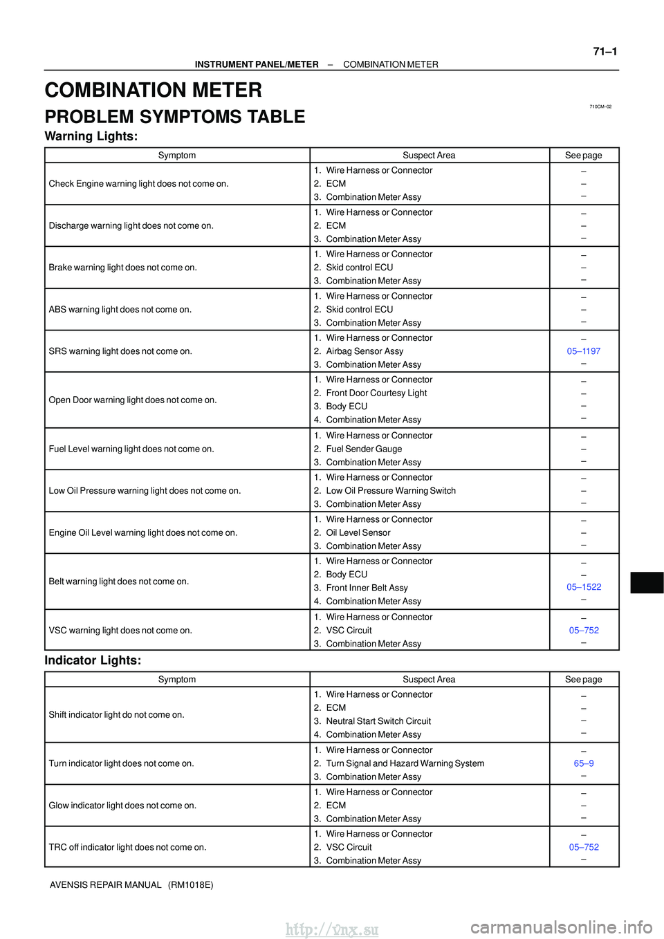
PROBLEM SYMPTOMS TABLE
Warning Lights:
SymptomSuspect AreaSee page
Check Engine warning light does not come on.
1.Wire Harness or Connector
2.ECM
3.Combination Meter Assy±
±
±
Discharge warning light does not come on.
1.Wire Harness or Connector
2.ECM
3.Combination Meter Assy±
±
±
Brake warning light does not come on.
1.Wire Harness or Connector
2.Skid control ECU
3.Combination Meter Assy±
±
±
ABS warning light does not come on.
1.Wire Harness or Connector
2.Skid control ECU
3.Combination Meter Assy±
±
±
SRS warning light does not come on.
1.Wire Harness or Connector
2.Airbag Sensor Assy
3.Combination Meter Assy±
05±1197 ±
Open Door warning light does not come on.
1.Wire Harness or Connector
2.Front Door Courtesy Light
3.Body ECU
4.Combination Meter Assy±
±
±
±
Fuel Level warning light does not come on.
1.Wire Harness or Connector
2.Fuel Sender Gauge
3.Combination Meter Assy±
±
±
Low Oil Pressure warning light does not come on.
1.Wire Harness or Connector
2.Low Oil Pressure Warning Switch
3.Combination Meter Assy±
±
±
Engine Oil Level warning light does not come on.
1.Wire Harness or Connector
2.Oil Level Sensor
3.Combination Meter Assy±
±
±
Belt warning light does not come on.
1.Wire Harness or Connector
2.Body ECU
3.Front Inner Belt Assy
4.Combination Meter Assy±
±
05±1522
±
VSC warning light does not come on.
1.Wire Harness or Connector
2.VSC Circuit
3.Combination Meter Assy±
05±752 ±
Indicator Lights:
SymptomSuspect AreaSee page
Shift indicator light do not come on.
1. Wire Harness or Connector
2. ECM
3. Neutral Start Switch Circuit
4. Combination Meter Assy±
±
±
±
Turn indicator light does not come on.
1. Wire Harness or Connector
2. Turn Signal and Hazard Warning System
3. Combination Meter Assy±
65±9 ±
Glow indicator light does not come on.
1. Wire Harness or Connector
2. ECM
3. Combination Meter Assy±
±
±
TRC off indicator light does not come on.
1. Wire Harness or Connector
2. VSC Circuit
3. Combination Meter Assy±
05±752 ±
http://vnx.su