Page 226 of 2234

TORQUE SPECIFICATION
1ZZ±FE/3ZZ±FE:
Part TightenedN�mkgf �cmft �lbf
Starter assy x Transaxle housing3")
031E7±03
±
SERVICE SPECIFICATIONS STARTING & CHARGING
03±33
AVENSIS REPAIR MANUAL (RM1018E)
TORQUE SPECIFICATION
1ZZ±FE/3ZZ±FE:
Part TightenedN�mkgf �cmft �lbf
Starter assy x Transaxle housing3737828
Starter wire x Starter assy9.81007
Generator assy x Transverse engine engine mounting bracket2525518
Generator assy x Cylinder block sub±assy5455140
Generator wire x Generator assy9.81007
Lead wire of field coil x Terminal C5.96052 in.� lbf
1AZ±FE/1AZ±FSE:
Part TightenedN�mkgf �cmft �lbf
Wire harness clamp bracket x Starter assy8.48674 in.� lbf
Starter assy x Cylinder block sub±assy3738028
Starter wire x Starter assy9.81007
Battery carrier x Body131319
Battery clamp sub±assy x Body5.05144 in.�lbf
Battery clamp sub±assy x Battery clamp bolt3.63631 in.�lbf
Terminal x Battery5.45548 in.�lbf
Wire harness clamp bracket x Generator assy8.48674 in.�lbf
Generator assy x Cylinder block sub±assy Bolt A
Bolt B52
21530
21438
16
Generator wire x Generator assy9.81007
Lead wire of field coil x Terminal C5.96052 in.� lbf
1CD±FTV:
Part TightenedN�mkgf �cmft �lbf
Starter x Transaxle Bolt
Terminal 3037
9.8377
10027
7.2
Generator assy x Engine M8
M10
Alternator wire Wire harness31
47
9.8
5.0320
475
100
5123
347
44 in.� lbf
Glow plug assy x Cylinder head Glow plug
Nut12.32.2125229
19 in.� lbf
Engine cover No. 1 x Cylinder head cover sub±assy8.08271 in.�lbf
Engine cover No. 1 x Intake manifold8.08271 in.�lbf
Front wheel RH1031,05076
http://vnx.su
Page 236 of 2234

RESISTANCE k�
(±4) (32) (80) (140)(104) (212)
(176)
A56275
VG
E2G THA
+B E2
Air
A31135
10±56
±
ENGINE CONTR")
100F0±02
321
45
±20
020 40 60
80100
0.1
0.2 0.3 0.5 1 2
35
10
20 30
TEMPERATURE �C( �F)
RESISTANCE k�
(±4) (32) (80) (140)(104) (212)
(176)
A56275
VG
E2G THA
+B E2
Air
A31135
10±56
±
ENGINE CONTROL SYSTEM ECD SYSTEM (1CD±FTV)
AVENSIS REPAIR MANUAL (RM1018E)
INSPECTION
1. INSPECT MASS AIR FLOW METER
(a) Output voltage inspection. (1) Apply battery voltage across terminals 3 (+B) and 4(E2G)
(2) Using a voltmeter, connect the positive (+) tester probe to terminal VG, and negative (±) tester probe
to terminal E2G.
(3) Blow air into the air flow meter, and check that the voltage fluctuates.
(b) Resistance inspection. (1) Using an ohmmeter, measure the resistance be-
tween terminals 2 (THA) and 1 (E2).
Resistance:
±20 �C (±4� F) 12.5 to 16.9 k �
20 �C (68� F) 2.19 to 2.67 k �
60 �C (140� F) 0.50 to 0.68 k �
2. INSPECT INTAKE SHUTTER ASSY
(a) Resistance inspection (Throttle control motor) (1) Using an ohmmeter, measure the resistance be-tween terminals.
Resistance:
TerminalsTemperatureResistance
2 ± 1, 3at 20� C (68� F)18 to 22 k�
5 ± 4, 6at 20�C (68� F)18 to 22 k�
http://vnx.su
Page 238 of 2234

AVENSIS REPAIR MANUAL (RM1018E)
6. INSPECT CRANKSHAFT POSITION SENSOR
(a) Resistance inspection. (1) Using")
A56277
NE±NE+
A57060
NE±
NE+
B16200
10±58
±
ENGINE CONTROL SYSTEM ECD SYSTEM (1CD±FTV)
AVENSIS REPAIR MANUAL (RM1018E)
6. INSPECT CRANKSHAFT POSITION SENSOR
(a) Resistance inspection. (1) Using an ohmmeter, measure the resistance be-
tween terminals.
Resistance:
at cold 1630 to 2740 �
at hot 2065 to 3225 �
NOTICE:
ºColdº and ºHotº in the following sentences express the
temperature of the sensor itself. ºColdº is from ±10 �C
(14 �F) to 50 �C (122� F) and ºHotº is from 50 �C (122� F) to
100 �C (212 �F).
7. INSPECT CAMSHAFT POSITION SENSOR
(a) Resistance inspection. (1) Using an ohmmeter, measure the resistance be-tween terminal.
Resistance:
at cold 1630 to 2740 �
at hot 2065 to 3225 �
NOTICE:
ºColdº and ºHotº in the following sentences express the
temperature of the sensor itself. ºColdº is from ±10 �C
(14 �F) to 50 �C (122� F) and ºHotº is from 50 �C (122� F) to
100 �C (212 �F).
8. INSPECT EDU RELAY
(a) Inspect the relay continuity. (1) Using an ohmmeter, check that there is continuitybetween terminals 1 and 2.
Specified condition: Continuity
(2) Check that there is no continuity between terminals 3 and 5.
Specified condition: No continuity
(b) Inspect the relay operation. (1) Apply battery voltage across terminals 1 and 2.
(2) Using an ohmmeter, check that there is continuitybetween terminals 3 and 5.
Specified condition: Continuity
http://vnx.su
Page 239 of 2234

10±59
AVENSIS REPAIR MANUAL (RM1018E)
9. INSPECT EFI MAIN RELAY
(a) Inspect the relay continuity.
(1) Using an ohmmeter, check that ther")
B16200
A31135
±
ENGINE CONTROL SYSTEM ECD SYSTEM (1CD±FTV)
10±59
AVENSIS REPAIR MANUAL (RM1018E)
9. INSPECT EFI MAIN RELAY
(a) Inspect the relay continuity.
(1) Using an ohmmeter, check that there is continuity
between terminals 1 and 2.
Specified condition: Continuity
(2) Check that there is no continuity between terminals 3 and 5.
Specified condition: No continuity
(b) Inspect the relay operation. (1) Apply battery voltage across terminals 1 and 2.
(2) Using an ohmmeter, check that there is continuitybetween terminals 3 and 5.
Specified condition: Continuity
10. INSPECT ACCELERATOR PEDAL ASSY
(a) Inspect the accel position sensor. (1) Using an ohmmeter, measure the resistance be-tween each terminal.
Resistance:
RHD:
Between terminalResistance
5 (VPA1) ± 1 (EP1)5.0 k� or less
2 (VPA2) ± 3 (EP2)5.0 k�or less
4 (VCP1) ± 1 (EP1)1.5 to 6.0 k �
6 (VCP2) ± 3 (EP2)1.5 to 6.0 k�
LHD:
Between terminalResistance
3 (VPA1) ± 4 (EP1)5.0 k�or less
6 (VPA2) ± 5 (EP2)5.0 k�or less
2 (VCP1) ± 4 (EP1)1.5 to 6.0 k �
1 (VCP2) ± 5 (EP2)1.5 to 6.0 k�
http://vnx.su
Page 243 of 2234
100FN±01
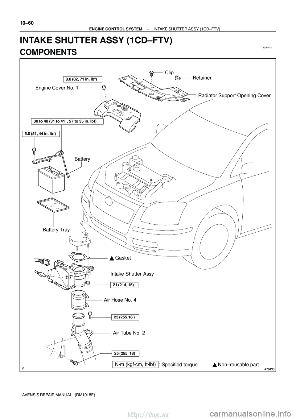
A79433N´m (kgf´cm, ft´lbf): Specified torque � Non±reusable part
�
Gasket
25 (255, 18)
25 (255,18 )
21 (214, 15)
30 to 40 (31 to 41 , 27 to 35 in. �lbf)
5.0 (51, 44 in. �lbf)
8.0 (82, 71 in. �lbf)
Radiator Support Opening Cover
Engine Cover No. 1
Battery
Battery Tray Intake Shutter Assy
Air Hose No. 4
Clip
Retainer
Air Tube No. 2
10±60
±
ENGINE CONTROL SYSTEM INTAKE SHUTTER ASSY (1CD±FTV)
AVENSIS REPAIR MANUAL (RM1018E)
INTAKE SHUTTER ASSY (1CD±FTV)
COMPONENTS
http://vnx.su
Page 244 of 2234

10±61
AVENSIS REPAIR MANUAL (RM1018E)
Removal & Installation and Disassembly & Reassembly
1")
100FO±01
A80092
B08171
A64328
2 to 7 mm0 to 4 mm
±
ENGINE CONTROL SYSTEM INTAKE SHUTTER ASSY (1CD±FTV)
10±61
AVENSIS REPAIR MANUAL (RM1018E)
Removal & Installation and Disassembly & Reassembly
1. REMOVE RADIATOR SUPPORT OPENING COVER
2. REMOVE ENGINE COVER NO.1
(a) Remove the 5 nuts and the engine cover.
3. REMOVE BATTERY
4. REMOVE AIR HOSE NO.4
(a) Loosen the 2 hose clamps.
(b) Remove the 2 bolts and separate the air tube No. 2.
(c) Remove the air hose No. 4.
5. REMOVE INTAKE SHUTTER ASSY
(a) Disconnect the 2 connectors.
(b) Remove the 3 nuts, then remove the intake shutter andthe gasket.
6. INSTALL INTAKE SHUTTER ASSY
(a) Install a new gasket and the intake shutter with the 3 nuts. Torque: 21 N �m (214 kgf� cm, 15 ft�lbf)
7. INSTALL AIR HOSE NO.4
(a) Install the air hose No. 4 to the air tube No. 2.
(b) Install the air tube No. 2 with the 2 bolts.
Torque: 25 N �m (255 kgf� cm, 18 ft�lbf)
(c) Install the air hose and hose clamp as shown in the il- lustration.
http://vnx.su
Page 245 of 2234
A64007
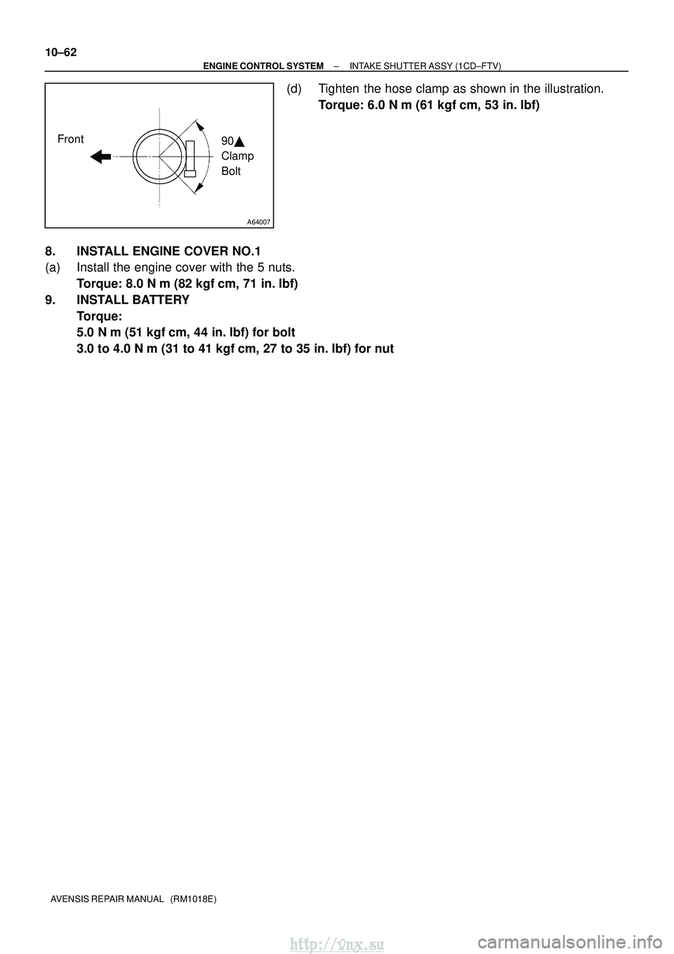
Front90�
Clamp
Bolt
10±62
±
ENGINE CONTROL SYSTEM INTAKE SHUTTER ASSY (1CD±FTV)
AVENSIS REPAIR MANUAL (RM1018E)
(d) Tighten the hose clamp as shown in the illustration. Torque: 6.0 N �m (61 kgf �cm, 53 in. �lbf)
8. INSTALL ENGINE COVER NO.1
(a) Install the engine cover with the 5 nuts. Torque: 8.0 N �m (82 kgf �cm, 71 in. �lbf)
9. INSTALL BATTERY Torque:
5.0 N� m (51 kgf �cm, 44 in. �lbf) for bolt
3.0 to 4.0 N� m (31 to 41 kgf �cm, 27 to 35 in.� lbf) for nut
http://vnx.su
Page 268 of 2234

RESISTANCE k�
(±4) (32) (80) (140)(104) (212)
(176)
Air
E2THAVG
E2G +B
A50378
12
Valve
A50377
B09641
10±20
�")
100G7±02
321
45
±20
020 40 60
80100
0.1
0.2 0.3 0.5 1 2
35
10
20 30
TEMPERATURE �C( �F)
RESISTANCE k�
(±4) (32) (80) (140)(104) (212)
(176)
Air
E2THAVG
E2G +B
A50378
12
Valve
A50377
B09641
10±20
±
ENGINE CONTROL SYSTEM SFI SYSTEM (1AZ±FE)
AVENSIS REPAIR MANUAL (RM1018E)
INSPECTION
1. INSPECT MASS AIR FLOW METER
(a) Output voltage inspection. (1) Apply battery voltage across terminals 1 (+B) and 2(E2G).
(2) Using a voltmeter, connect the positive (+) tester probe to terminal 3 (VG), and negative (±) tester
probe to terminal 2 (E2G).
(3) Blow air into the MAF meter, and check that the volt- age fluctuates.
(b) Resistance inspection. (1) Using an ohmmeter, measure the resistance be-
tween terminals 4 (THA) and 5 (E2).
Resistance:
TerminalsResistanceTemperature
THA ± E213.6 to 18.4 k�±20 �C (±4 �F)
THA ± E22.21 to 2.69 k�20 �C (68 �F)
THA ± E20.49 to 0.67 k�60 �C (140 �F)
2. INSPECT CAMSHAFT TIMING OIL CONTROL VALVE
ASSY
(a) Resistance inspection. (1) Using an ohmmeter, measure the resistance be-
tween the terminals.
Resistance: 6.9 to 7.9 � at 20 � C (68 �F)
(b) Movement inspection. (1) Connect the positive (+) lead from the battery to ter-minal 1 and negative (±) lead to terminal 2, and
check the movement of the valve.
NOTICE:
Confirm the valve does not adhere.
HINT:
Bad returning of the valve by entrance of foreign objects causes
subtle pressure leak to the advanced direction. Then, DTC can
be detected.
3. INSPECT THROTTLE BODY ASSY
(a) Check throttle body. (1) Check that throttle valve shaft is not rickety.
(2) Check that each port is not stopped up.
(3) Check that throttle valve opens and closes smooth-
ly.
(4) Check that there is no clearance between the
throttle stop screw and throttle lever when the
closed throttle position.
http://vnx.su