Page 418 of 2234

AVENSIS RE")
A77115
Ohmmeter
Resistance
A77116
Ohmmeter
No continuity
A77117
Air
E
F
A77118
Air
E
F
Battery
A64543
+B
Bank 2 Sensor 1: HT
E1
12±14
±
EMISSION CONTROL EMISSION CONTROL SYSTEM (1AZ±FSE)
AVENSIS REPAIR MANUAL (RM1018E)
4. INSPECT VACUUM SWITCHING VALVE ASSY NO.1
(a) Inspect VSV for open circuit. (1) Using an ohmmeter, measure resistance between
the terminals.
Resistance: 26 to 30 � at 20 �C (68� F)
If the resistance is not as specified, replace the VSV.
(b) Inspect the VSV for ground. (1) Using an ohmmeter, check that there is no continu-
ity between each terminal and the body.
If there is continuity, replace the VSV.
(c) Inspect the VSV operation. (1) Check that air flows with a little difficulty from port Eto port F.
(2) Apply battery voltage across the terminals.
(3) Check that air flows from port E to port F.
If operation is not as specified, replace the VSV.
5. INSPECT HEATED OXYGEN SENSOR
(a) Bank 2 Sensor 1: (1) Using an ohmmeter, measure the resistance be-
tween the terminals.
Resistance:
Terminal No.Resistance
1 (HT) ± 2 (+B)11 to 16 � at 20 �C (68 �F)
1 (HT) ± 4 (E1)No Continuity
If the resistance is not as specified, replace the sensor.
http://vnx.su
Page 424 of 2234

A77118
Air
E
F
Battery
A60562
Cylinder Head Side
A60563
Intake Manifold Side
A64543
+B
Bank 1 Sensor 1: HT1A
E1
A77126
HT
+B
Bank 1 Sensor 2:
E1
12±4
±
EMISSION CONTROL EMISSION CONTROL SYSTEM (1ZZ±FE/3ZZ±FE)
AVENSIS REPAIR MANUAL (RM1018E)
(2) Apply battery voltage across the terminals.
(3) Check that air flows from port E to port F.
If operation is not as specified, replace the VSV.
3. INSPECT VENTILATION VALVE SUB±ASSY
(a) Blow air into the cylinder head side, and check that air
passes through easily.
CAUTION:
Do not suck air through the valve. If contains petroleum
substances and is harmful.
(b) Blow air into the intake manifold side, and check that air passes through with difficulty.
HINT:
If operation is not as specified, replace the PCV valve.
4. IINSPECT HEATED OXYGEN SENSOR
(a) Bank 1 Sensor 1: (1) Using an ohmmeter, measure the resistance be-tween the terminals.
Resistance:
Terminal No.Resistance
1 (HT1A) ± 2 (+B)5 to 10 � at 20 �C (68 �F)
1 (HT1A) ± 4 (E1)No Continuity
If the resistance is not as specified, replace the sensor.
(b) Bank 1 Sensor 2:
(1) Using an ohmmeter, measure the resistance be-
tween the terminals.
Resistance:
Terminal No.Resistance
1 (HT) ± 2 (+B)11 to 16 � at 20 �C (68 �F)
1 (HT) ± 4 (E1)No Continuity
If the resistance is not as specified, replace the sensor.
http://vnx.su
Page 428 of 2234
1306S±02
A79032
Filter
AB
A59586
13±2
±
INTAKE INTAKE AIR CONTROL SYSTEM (1AZ±FSE)
AVENSIS REPAIR MANUAL (RM1018E)
INSPECTION
1. INSPECT INTAKE AIR CONTROL VALVE ASSY
(a) With 34.7 kPa (260 mm Hg, 10.2 in. Hg) of vacuum ap- plied to the actuator, check that the actuator rod moves.
(b) One minute after applying the vacuum, check that the ac- tuator rod does not return.
(c) If the operation is not as specified, replace the intake air control valve assembly.
NOTICE:
Do not touch the adjust screw.
2. INSPECT VACUUM SWITCHING VALVE ASSY NO.1
(a) Using an ohmmeter, measure resistance between each terminal.
Resistance: 33 to 39 � at 20 �C (68� F)
(b) Check that air flows form port B to the filter.
(c) Apply battery voltage across the terminals.
(d) Check that air flows from port B to port A.
http://vnx.su
Page 432 of 2234
13030±02
A60591
A60592
A60593
Air
E G
A60594
Air
Filter Battery
E
±
INTAKE TURBO CHARGER SYSTEM (1CD±FTV)
13±7
AVENSIS REPAIR MANUAL (RM1018E)
INSPECTION
1. VACUUM SWITCHING VALVE ASSY NO.1
(a) Inspect VSV for open circuit.
(1) Using an ohmmeter, check that the there is continu-ity between the terminals.
Resistance: 37 ± 44 � at 20 �C (68� F)
(b) Inspect VSV for ground. (1) Using an ohmmeter, check that there is no continu-ity between each terminal and the body.
Specified condition: No continuity
(c) Inspect VSV operation. (1) Check that air flows from port E to G.
(2) Apply battery voltage across the terminals.
(3) Check that air flows from port E to filter.
http://vnx.su
Page 539 of 2234
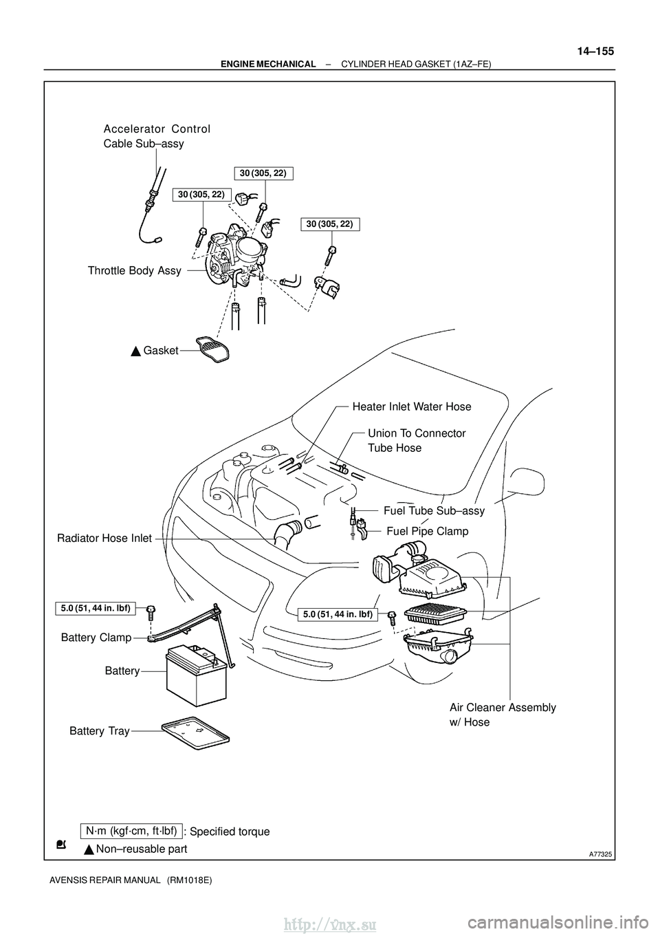
A77325
N´m (kgf´cm, ft´lbf): Specified torque
� Non±reusable part �
Gasket
Accelerator Control
Cable Sub±assy
30 (305, 22)
30 (305, 22)
Throttle Body Assy
Heater Inlet Water Hose
Union To Connector
Tube Hose
Fuel Tube Sub±assy
Fuel Pipe ClampRadiator Hose Inlet
Battery Clamp
Battery
Battery Tray
Air Cleaner Assembly
w/ Hose
30 (305, 22)
5.0 (51, 44 in. �lbf)5.0 (51, 44 in. �lbf)
±
ENGINE MECHANICAL CYLINDER HEAD GASKET (1AZ±FE)
14±155
AVENSIS REPAIR MANUAL (RM1018E)
http://vnx.su
Page 546 of 2234

AVENSIS REPAIR MANUAL (RM1018E)
22.REMOVE ENGINE SERVICE COVER BRACKET RH (RHD(W/ AIR CONDITIONER) STEERING POSITION TYPE)
(a)Remove")
A77302
14±162
±
ENGINE MECHANICALCYLINDER HEAD GASKET(1AZ±FE)
AVENSIS REPAIR MANUAL (RM1018E)
22.REMOVE ENGINE SERVICE COVER BRACKET RH (RHD(W/ AIR CONDITIONER) STEERING POSITION TYPE)
(a)Remove the bolt and the engine service cover bracket RH.
23.REMOVE CYLINDER HEAD COVER SUB±ASSY (See page 14±139)
24.SET NO. 1 CYLINDER TO TDC/COMPRESSION (See page 14±139)
25.REMOVE ENGINE MOUNTING BRACKET NO.2 RH (See page 14±139)
26.REMOVE TRANSVERSE ENGINE ENGINE MOUNTING INSULATOR (See page 14±139)
27.REMOVE CRANKSHAFT PULLEY (See page 14±139)
SST09213±54015 (91651±60855), 09330±00021, 09950±50013 (0995\
1±05010, 09952±05010, 09953±05020, 09954±05021)
28.REMOVE CHAIN TENSIONER ASSY NO.1 (See page 14±139)
29.REMOVE CRANKSHAFT POSITION SENSOR (See page 18±17)
30.REMOVE OIL PAN SUB±ASSY (See page 14±139) SST09032±00100
31.REMOVE V±RIBBED BELT TENSIONER ASSY (See page 14±139)
32.REMOVE TIMING CHAIN OR BELT COVER SUB±ASSY (See page 14±139)
33.REMOVE CRANKSHAFT POSITION SENSOR PLATE NO.1
34.REMOVE CHAIN TENSIONER SLIPPER
35.REMOVE CHAIN VIBRATION DAMPER NO.1
36.REMOVE TIMING CHAIN GUIDE (See page 14±139)
37.REMOVE CHAIN SUB±ASSY
38.REMOVE BATTERY 39.REMOVE AIR CLEANER ASSEMBLY WITH HOSE
(a)Disconnect the 2 connectors.
(b)Disconnect the air cleaner hose from the throttle body.
(c)Raise a clamp up, and slide it toward the air cleaner cap,then remove the air cleaner cap from its case.
(d)Remove the air cleaner element.
(e)Remove the 4 bolts and the air cleaner case.
40.DISCONNECT RADIATOR HOSE INLET
41.DISCONNECT UNION TO CONNECTOR TUBE HOSE
42.DISCONNECT HEATER INLET WATER HOSE (W/ AIR CONDITIONING)
43.SEPARATE FUEL TUBE SUB±ASSY (See page 11±26)
44. SEPARATE ENGINE WIRE
http://vnx.su
Page 554 of 2234

AVENSIS REPAIR MANUAL (RM1018E)
24.REMOVE COOL ER BRACKET (LHD STEER ING
POSITION TYPE)
(a)Remove the bolt and the cooler bra")
A77340
A77335
14±256
±
ENGINE MECHANICALCYLINDER HEAD GASKET(1AZ±FSE)
AVENSIS REPAIR MANUAL (RM1018E)
24.REMOVE COOL ER BRACKET (LHD STEER ING
POSITION TYPE)
(a)Remove the bolt and the cooler bracket.
25.REMOVE ENGINE SERVICE COVER BRACKET RH (RHD STEERING POSITION TYPE)
(a)Remove the bolt and the engine service cover bracket RH.
26.REMOVE CYLINDER HEAD COVER SUB±ASSY (See page 14±222)
27.SET NO. 1 CYLINDER TO TDC/COMPRESSION (See page 14±222)
28.REMOVE ENGINE MOUNTING BRACKET NO.2 RH (See page 14±222 )
29 .
REMOVE TRANSVERSE ENGINE ENGINE MOUNTING INSULATOR (See page
14±222)
30 . REMOVE CRANKSHAFT PULLEY (
See page 14±222)
SST 09213±54015 (91651±60855), 09330±00021, 09950±50013 (0995\
1±05010, 09952±05010, 09953±05020, 09954±05021)
31.REMOVE CHAIN TENSIONER ASSY NO.1 (See page 14±222)
32.REMOVE CRANKSHAFT POSITION SENSOR (See page 18±17)
33.REMOVE OIL PAN SUB±ASSY (See page 14±222)
SST 09032±00100
34.REMOVE V±RIBBED BELT TENSIONER ASSY (See page 14±222)
35.REMOVE TIMING CHAIN OR BELT COVER SUB±ASSY (See page 14±222)
36.REMOVE CRANKSHAFT POSITION SENSOR PLATE NO.1 (See page 14±222)
37. REMOVE CHAIN TENSIONER SLIPPER
38. REMOVE CHAIN VIBRATION DAMPER NO.1
39.REMOVE TIMING CHAIN GUIDE (See page 14±222)
40. REMOVE CHAIN SUB±ASSY
41. REMOVE BATTERY
42. REMOVE AIR CLEANER ASSEMBLY WITH HOSE
(a) Disconnect the 2 connectors.
(b) Disconnect the 2 vacuum hoses.
(c) Disconnect the ventilation hose.
(d) Disconnect the air cleaner hose from the throttle body.
http://vnx.su
Page 561 of 2234
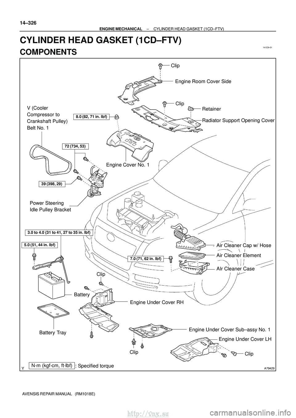
141C9±01
A79429N´m (kgf´cm, ft´lbf): Specified torque
8.0 (82, 71 in.�lbf)
72 (734, 53)
39 (398, 29)
5.0 (51, 44 in. �lbf)
3.0 to 4.0 (31 to 41, 27 to 35 in.� lbf)
Engine Cover No. 1Engine Room Cover Side
Radiator Support Opening Cover
Power Steering
Idle Pulley Bracket
Battery Engine Under Cover Sub±assy No. 1Engine Under Cover LH
Battery Tray
Air Cleaner Cap w/ Hose
Air Cleaner Element
AIr Cleaner Case
7.0 (71, 62 in.
�lbf)
Engine Under Cover RH
V (Cooler
Compressor to
Crankshaft Pulley)
Belt No. 1
Clip
Clip
Retainer
Clip
Clip
Clip
14±326
±
ENGINE MECHANICAL CYLINDER HEAD GASKET (1CD±FTV)
AVENSIS REPAIR MANUAL (RM1018E)
CYLINDER HEAD GASKET (1CD±FTV)
COMPONENTS
http://vnx.su

AVENSIS REPAIR MANUAL (RM1018E)
INSPECTION
1. INSPECT INTAKE AIR CONTROL VALVE ASSY
(a) With 34.7 kPa (260 mm H")

13±7
AVENSIS REPAIR MANUAL (RM1018E)
INSPECTION
1. VACUUM SWITCHING VALVE ASSY NO.1
(a)")