Page 1679 of 2234
720J6±01
B70316
Claw
Claw
±
SEAT FRONT SEAT ASSEMBLY LH (POWER SEAT TYPE)
72±11
AVENSIS REPAIR MANUAL (RM1018E)
OVERHAUL
CAUTION:
�Wear safety gloves, because the cutting surface of the seatback frame and se\
at adjuster may
injure your hand.
�Work must be started more than 90 seconds after the ignition switch is turne\
d to the LOCK posi-
tion and the negative (±) terminal cable is disconnected from the b\
attery.
(The SRS is equipped with a back±up power source. If work is started within 90 se\
conds from
disconnecting the negative (±) terminal cable of the battery, the SRS may be deployed.)
HINT:
�The installation is in the reverse order of the removal. However, when there is a special point concern-
ing the installation, it is indicated.
�Use the same procedures on the RH side as on the LH side.
1. REMOVE FRONT SEAT ASSY LH
(a) Remove the headrest.
(b) Using a screwdriver, remove the 2 seat track covers.
HINT:
Tape the screwdriver tip before use.
(c) Disconnect the connectors under the seat.
(d) Remove the 4 bolts and seat.
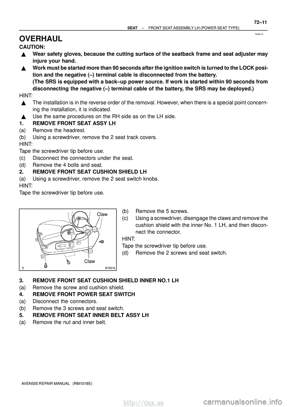
2. REMOVE FRONT SEAT CUSHION SHIELD LH
(a) Using a screwdriver, remove the 2 seat switch knobs.
HINT:
Tape the screwdriver tip before use.
(b) Remove the 5 screws.
(c) Using a screwdriver, disengage the claws and remove thecushion shield with the inner No. 1 LH, and then discon-
nect the connector.
HINT:
Tape the screwdriver tip before use.
(d) Remove the 2 screws and seat switch.
3. REMOVE FRONT SEAT CUSHION SHIELD INNER NO.1 LH
(a) Remove the screw and cushion shield.
4. REMOVE FRONT POWER SEAT SWITCH
(a) Disconnect the connectors.
(b) Remove the 3 screws and seat switch.
5. REMOVE FRONT SEAT INNER BELT ASSY LH
(a) Remove the nut and inner belt.
http://vnx.su
Page 1701 of 2234
720JH±01
\b�����\b�����
B70589
A B
12 12345
(k �)
65�
18 �
0
0
0.42 ± 0.28 4.08 ± 2.72
ON
OFF
65
�
B70591
12 12345
A
B
±
SEAT SEAT HEATER SYSTEM
72±37
AVENSIS REPAIR MANUAL (RM1018E)
INSPECTION
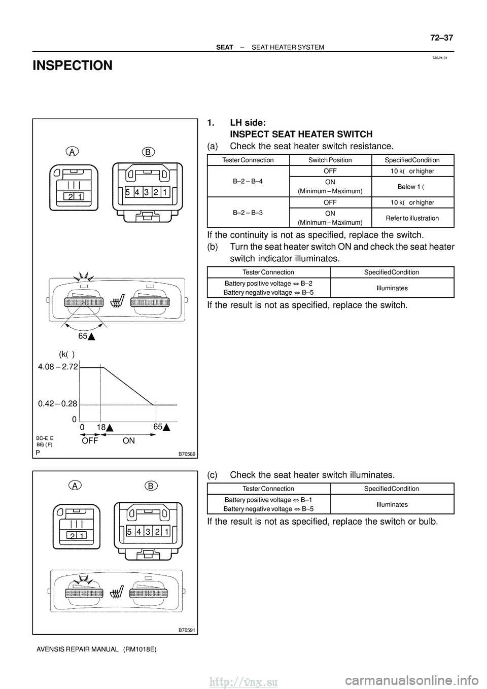
1. LH side:
INSPECT SEAT HEATER SWITCH
(a) Check the seat heater switch resistance.
Tester ConnectionSwitch PositionSpecified Condition
OFF10 k� or higher
B±2 ± B±4ON
(Minimum ± Maximum)Below 1 �
OFF10 k�or higher
B±2 ± B±3ON
(Minimum ± Maximum)Refer to illustration
If the continuity is not as specified, replace the switch.
(b) Turn the seat heater switch ON and check the seat heater switch indicator illuminates.
Tester ConnectionSpecified Condition
Battery positive voltage �B±2
Battery negative voltage �B±5Illuminates
If the result is not as specified, replace the switch.
(c) Check the seat heater switch illuminates.
Tester ConnectionSpecified Condition
Battery positive voltage �B±1
Battery negative voltage �B±5Illuminates
If the result is not as specified, replace the switch or bulb.
http://vnx.su
Page 1702 of 2234
\b�����\b�����
B70880
12 12345
(k �)
65�
18 �
0
0
0.42 ± 0.28 4.08 ± 2.72
ON
OFF 65
�
AB
B70881
12
12345
A
B
72±38
±
SEAT SEAT HEATER SYSTEM
AVENSIS REPAIR MANUAL (RM1018E)
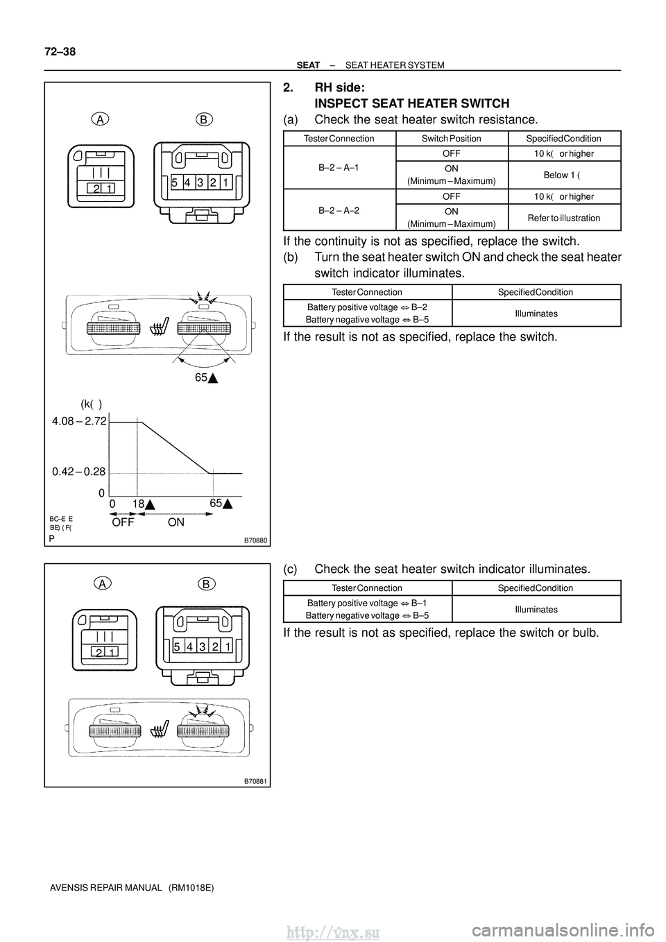
2. RH side: INSPECT SEAT HEATER SWITCH
(a) Check the seat heater switch resistance.
Tester ConnectionSwitch PositionSpecified Condition
OFF10 k� or higher
B±2 ± A±1ON
(Minimum ± Maximum)Below 1 �
OFF10 k�or higher
B±2 ± A±2ON
(Minimum ± Maximum)Refer to illustration
If the continuity is not as specified, replace the switch.
(b) Turn the seat heater switch ON and check the seat heater switch indicator illuminates.
Tester ConnectionSpecified Condition
Battery positive voltage �B±2
Battery negative voltage �B±5Illuminates
If the result is not as specified, replace the switch.
(c) Check the seat heater switch indicator illuminates.
Tester ConnectionSpecified Condition
Battery positive voltage �B±1
Battery negative voltage �B±5Illuminates
If the result is not as specified, replace the switch or bulb.
http://vnx.su
Page 1703 of 2234
B70436
12
B70436
12
12
B68349
A B
12
B68349
AB
B68374
2 1
5
3
±
SEAT SEAT HEATER SYSTEM
72±39
AVENSIS REPAIR MANUAL (RM1018E)
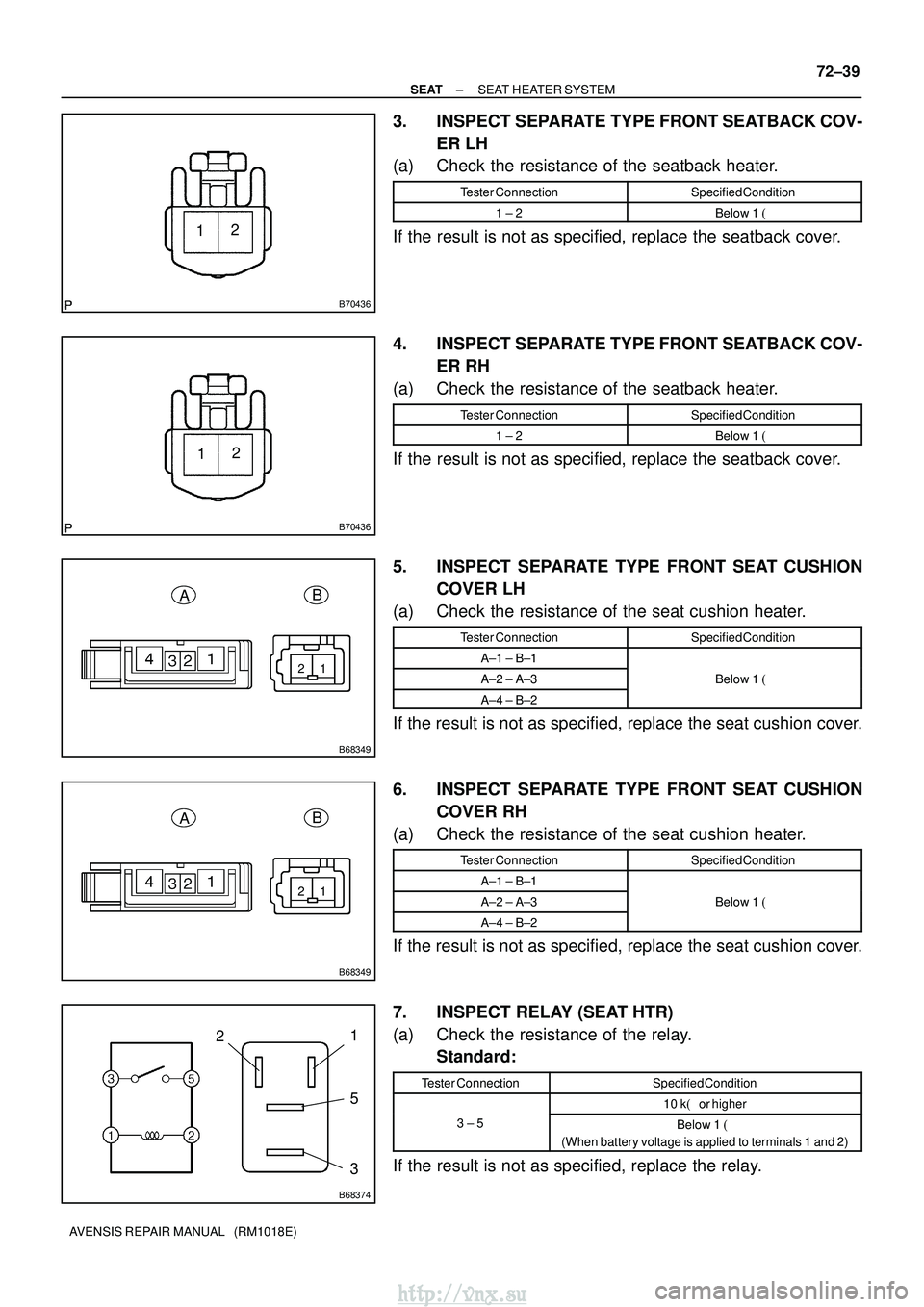
3. INSPECT SEPARATE TYPE FRONT SEATBACK COV-
ER LH
(a) Check the resistance of the seatback heater.
Tester ConnectionSpecified Condition
1 ± 2Below 1 �
If the result is not as specified, replace the seatback cover.
4. INSPECT SEPARATE TYPE FRONT SEATBACK COV-
ER RH
(a) Check the resistance of the seatback heater.
Tester ConnectionSpecified Condition
1 ± 2Below 1 �
If the result is not as specified, replace the seatback cover.
5. INSPECT SEPARATE TYPE FRONT SEAT CUSHION
COVER LH
(a) Check the resistance of the seat cushion heater.
Tester ConnectionSpecified Condition
A±1 ± B±1
A±2 ± A±3Below 1 �
A±4 ± B±2
If the result is not as specified, replace the seat cushion cover.
6. INSPECT SEPARATE TYPE FRONT SEAT CUSHION
COVER RH
(a) Check the resistance of the seat cushion heater.
Tester ConnectionSpecified Condition
A±1 ± B±1
A±2 ± A±3Below 1 �
A±4 ± B±2
If the result is not as specified, replace the seat cushion cover.
7. INSPECT RELAY (SEAT HTR)
(a) Check the resistance of the relay.
Standard:
Tester ConnectionSpecified Condition
10 k� or higher
3 ± 5Below 1 �
(When battery voltage is applied to terminals 1 and 2)
If the result is not as specified, replace the relay.
http://vnx.su
Page 1707 of 2234
73095±02
B68828
Fuel Lid Opener Switch
B68829
Shaft StrokesOpen
73±30
±
THEFT DETERRENT & DOOR LOCK FUEL LID OPENER SYSTEM
AVENSIS REPAIR MANUAL (RM1018E)
INSPECTION
1. INSPECT FUEL LID OPENER SWITCH
(a) Check the switch resistance. Standard:
Tester ConnectionSwitch PositionSpecified Condition
23OFF10 k� or higher2 ± 3ONBelow 1 �
If the result is not as specified, replace the switch.
2. INSPECT FUEL LID LOCK CONTROL ASSY
(a) Apply battery voltage to the lock control and check the
motor operates in the direction.
Standard:
Measurement ConditionSpecified Condition
Battery positive (+) � Terminal 2
Battery negative (±) � Terminal 1Open direction
If the result is not as specified, replace the lock control assy.
(b) Check the shaft strokes.
Standard: 18.0 mm (0.709 in.) or more
http://vnx.su
Page 1710 of 2234
73±2
±
THEFT DETERRENT & DOOR LOCK POWER DOOR LOCK CONTROL SYSTEM
AVENSIS REPAIR MANUAL (RM1018E)
(d) Check the illumination function. (1) Set the room light switch in the DOOR position.
(2) With all doors locked, check that all doors unlock when the driver side door\
lock cylinder is turnedto UNLOCK using the key and that the room right turns on.
(3) Check that the room light turns off in approx. 15 seconds after the doors have not been opened for a while.
3. w/ Double lock:
CHECK DOUBLE LOCKING FUNCTION SYSTEM
(a) Check that the double locking system is set to ON. (1) Open all the windows.
(2) Turn the ignition switch to LOCK and remove the key.
(3) Open and close the driver side door, and make sure that all doors including the back door areclosed securely.
(4) Push the LOCK switch on the wireless transmitter twice within 5 seconds, and check that the hazard warning lights flash once at this time to show that the system is set.
(5) Try to unlock all doors using the inside handle of the vehicle, and check\
that none of the doors
unlock.
NOTICE:
�The double locking system cannot be set to ON without using the wireless\
transmitter.
�The double locking system operation is not related to the back door.
(b) Check that the double locking system is set to OFF. (1) Push the UNLOCK switch on the wireless transmitter while the double locking system is ON, andcheck that the hazard warning lights flash twice at this time to show th\
at the system is set to OFF.
(2) Check that the doors can be opened both by the inside handle and the outside \
handle.
NOTICE:
If the battery of the wireless transmitter is dead, only the driver side\
door can be opened using the
key. However, the theft deterrent system still remains on. Therefore, be aware that\
the theft alarm
is set off when the door is opened without the use of the wireless trans\
mitter.
http://vnx.su
Page 1711 of 2234
730GW±01
B65427
Unlock
Lock
B65428
UnlockLock
±
THEFT DETERRENT & DOOR LOCK POWER DOOR LOCK CONTROL SYSTEM
73±3
AVENSIS REPAIR MANUAL (RM1018E)
INSPECTION
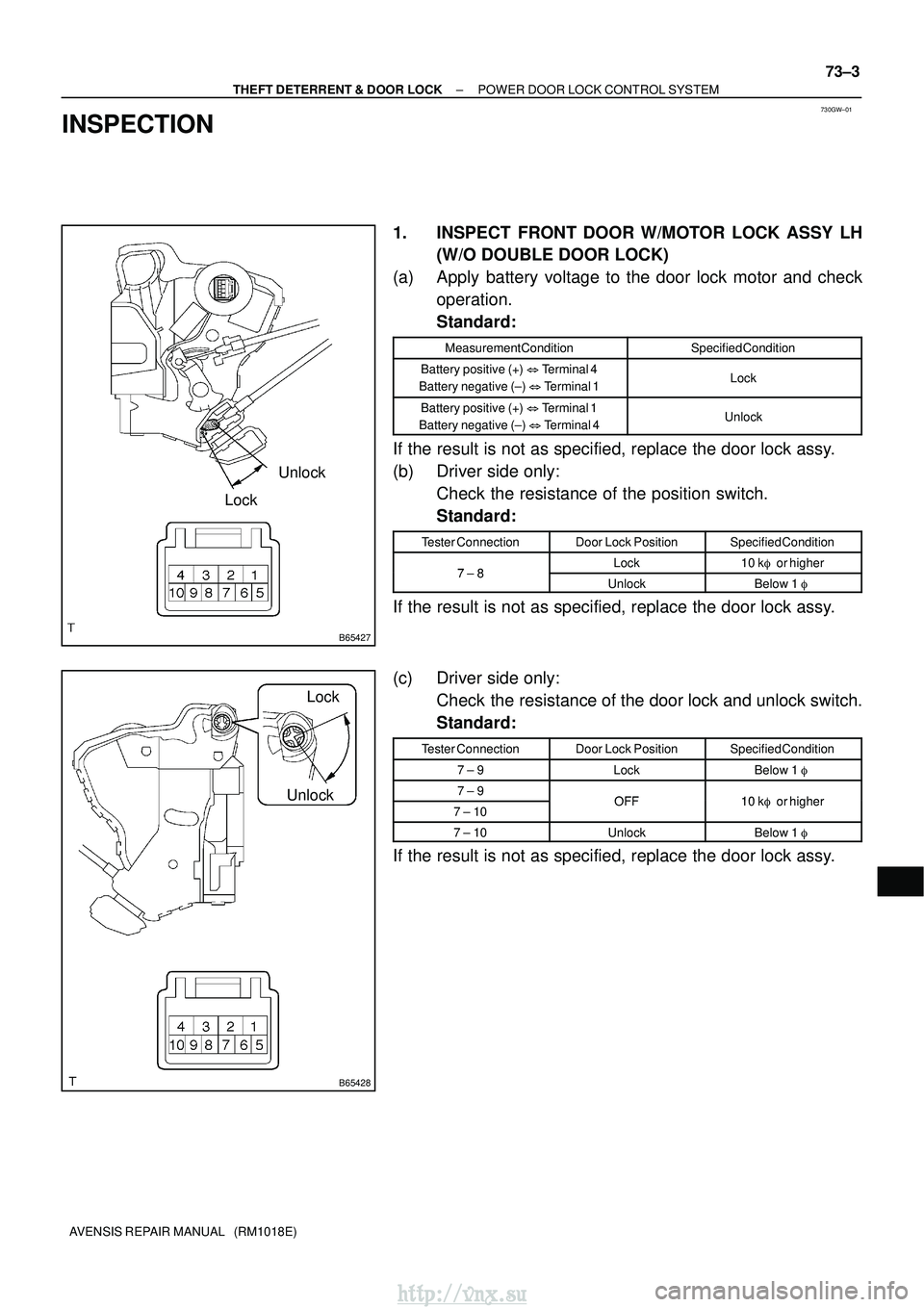
1. INSPECT FRONT DOOR W/MOTOR LOCK ASSY LH
(W/O DOUBLE DOOR LOCK)
(a) Apply battery voltage to the door lock motor and check operation.
Standard:
Measurement ConditionSpecified Condition
Battery positive (+) � Terminal 4
Battery negative (±) � Terminal 1Lock
Battery positive (+) � Terminal 1
Battery negative (±) � Terminal 4Unlock
If the result is not as specified, replace the door lock assy.
(b) Driver side only:
Check the resistance of the position switch.
Standard:
Tester ConnectionDoor Lock PositionSpecified Condition
78Lock10 k� or higher7 ± 8UnlockBelow 1 �
If the result is not as specified, replace the door lock assy.
(c) Driver side only:
Check the resistance of the door lock and unlock switch.
Standard:
Tester ConnectionDoor Lock PositionSpecified Condition
7 ± 9LockBelow 1 �
7 ± 9OFF10 k�or higher7 ± 10OFF10 k�or higher
7 ± 10UnlockBelow 1 �
If the result is not as specified, replace the door lock assy.
http://vnx.su
Page 1712 of 2234
B65429
Unlock
Lock
B65430
Unlock
Lock
73±4
±
THEFT DETERRENT & DOOR LOCK POWER DOOR LOCK CONTROL SYSTEM
AVENSIS REPAIR MANUAL (RM1018E)
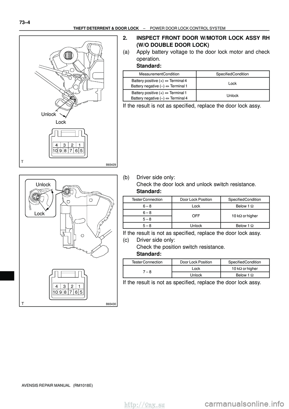
2. INSPECT FRONT DOOR W/MOTOR LOCK ASSY RH (W/O DOUBLE DOOR LOCK)
(a) Apply battery voltage to the door lock motor and check
operation.
Standard:
Measurement ConditionSpecified Condition
Battery positive (+) � Terminal 4
Battery negative (±) � Terminal 1Lock
Battery positive (+) � Terminal 1
Battery negative (±) � Terminal 4Unlock
If the result is not as specified, replace the door lock assy.
(b) Driver side only:
Check the door lock and unlock switch resistance.
Standard:
Tester ConnectionDoor Lock PositionSpecified Condition
6 ± 8LockBelow 1 �
6 ± 8OFF10 k�or higher5 ± 8OFF10 k�or higher
5 ± 8UnlockBelow 1 �
If the result is not as specified, replace the door lock assy.
(c) Driver side only:
Check the position switch resistance.
Standard:
Tester ConnectionDoor Lock PositionSpecified Condition
78Lock10 k� or higher7 ± 8UnlockBelow 1 �
If the result is not as specified, replace the door lock assy.
http://vnx.su