Page 1640 of 2234
700TD±01
B67055
12345678
EILL+
B67056
1.4 W
Test Bulb
Switch ON
5 (IG)
8 (E) 3 (DEF)
B69288
12345678
EILL+
70±50
±
WINDSHIELD/WINDOWGLASS/MIRROR WINDOW DEFOGGER SYSTEM
AVENSIS REPAIR MANUAL (RM1018E)
INSPECTION
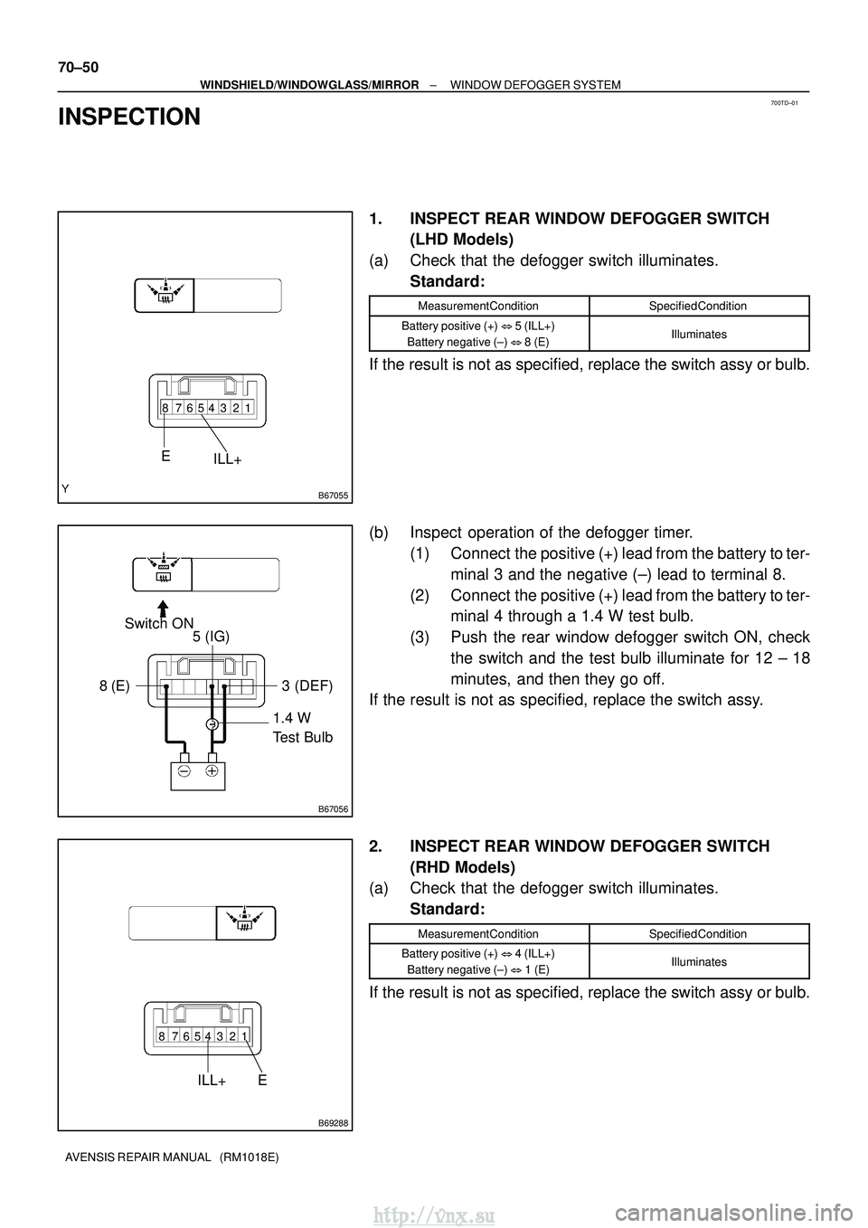
1. INSPECT REAR WINDOW DEFOGGER SWITCH (LHD Models)
(a) Check that the defogger switch illuminates. Standard:
Measurement ConditionSpecified Condition
Battery positive (+) � 5 (ILL+)
Battery negative (±) �8 (E)Illuminates
If the result is not as specified, replace the switch assy or bulb.
(b) Inspect operation of the defogger timer.
(1) Connect the positive (+) lead from the battery to ter-minal 3 and the negative (±) lead to terminal 8.
(2) Connect the positive (+) lead from the battery to ter- minal 4 through a 1.4 W test bulb.
(3) Push the rear window defogger switch ON, check the switch and the test bulb illuminate for 12 ± 18
minutes, and then they go off.
If the result is not as specified, replace the switch assy.
2. INSPECT REAR WINDOW DEFOGGER SWITCH
(RHD Models)
(a) Check that the defogger switch illuminates.
Standard:
Measurement ConditionSpecified Condition
Battery positive (+) � 4 (ILL+)
Battery negative (±) � 1 (E)Illuminates
If the result is not as specified, replace the switch assy or bulb.
http://vnx.su
Page 1641 of 2234
B69289
1.4 W
Test Bulb
Switch ON
5 (IG)
6 (DEF) 1 (E)
B67057
B67058
1.4 W Test Bulb
Switch ON 1 (IG)
6 (D)
3 (E)
±
WINDSHIELD/WINDOWGLASS/MIRROR WINDOW DEFOGGER SYSTEM
70±51
AVENSIS REPAIR MANUAL (RM1018E)
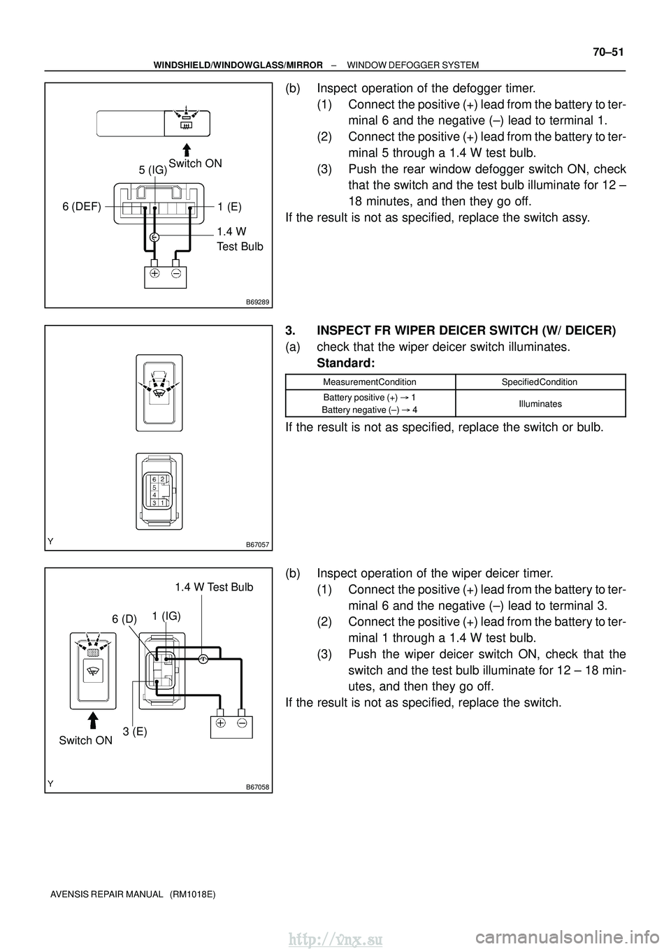
(b) Inspect operation of the defogger timer.
(1) Connect the positive (+) lead from the battery to ter-minal 6 and the negative (±) lead to terminal 1.
(2) Connect the positive (+) lead from the battery to ter- minal 5 through a 1.4 W test bulb.
(3) Push the rear window defogger switch ON, check that the switch and the test bulb illuminate for 12 ±
18 minutes, and then they go off.
If the result is not as specified, replace the switch assy.
3. INSPECT FR WIPER DEICER SWITCH (W/ DEICER)
(a) check that the wiper deicer switch illuminates. Standard:
Measurement ConditionSpecified Condition
Battery positive (+) � 1
Battery negative (±) � 4Illuminates
If the result is not as specified, replace the switch or bulb.
(b) Inspect operation of the wiper deicer timer.
(1) Connect the positive (+) lead from the battery to ter-minal 6 and the negative (±) lead to terminal 3.
(2) Connect the positive (+) lead from the battery to ter-
minal 1 through a 1.4 W test bulb.
(3) Push the wiper deicer switch ON, check that the switch and the test bulb illuminate for 12 ± 18 min-
utes, and then they go off.
If the result is not as specified, replace the switch.
http://vnx.su
Page 1642 of 2234
B68230
12
3
4
5
6
7
4 (H+)
5 (H±)
B68231
12
3
4
5
6
7
4 (H+)
5 (H±)
B70597
70±52
±
WINDSHIELD/WINDOWGLASS/MIRROR WINDOW DEFOGGER SYSTEM
AVENSIS REPAIR MANUAL (RM1018E)
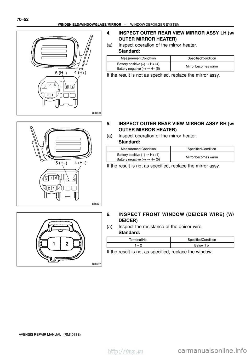
4. INSPECT OUTER REAR VIEW MIRROR ASSY LH (w/ OUTER MIRROR HEATER)
(a) Inspect operation of the mirror heater.
Standard:
Measurement ConditionSpecified Condition
Battery positive (+) � H+ (4)
Battery negative (±) � H± (5)Mirror becomes warm
If the result is not as specified, replace the mirror assy.
5. INSPECT OUTER REAR VIEW MIRROR ASSY RH (w/
OUTER MIRROR HEATER)
(a) Inspect operation of the mirror heater. Standard:
Measurement ConditionSpecified Condition
Battery positive (+) � H+ (4)
Battery negative (±) � H± (5)Mirror becomes warm
If the result is not as specified, replace the mirror assy.
6. INSPECT FRONT WINDOW (DEICER WIRE) (W/
DEICER)
(a) Inspect the resistance of the deicer wire. Standard:
Terminal No.Specified Condition
1 ± 2Below 1 �
If the result is not as specified, replace the window.
http://vnx.su
Page 1643 of 2234
B66134
Tester ProbeTin FoilDefogger Wire
B63720
At Center
V
B63721
0 V
Broken
Wire Less than
10V
Battery
Side
Ground SideFoil Strip
�
�
±
WINDSHIELD/WINDOWGLASS/MIRROR WINDOW DEFOGGER SYSTEM
70±53
AVENSIS REPAIR MANUAL (RM1018E)
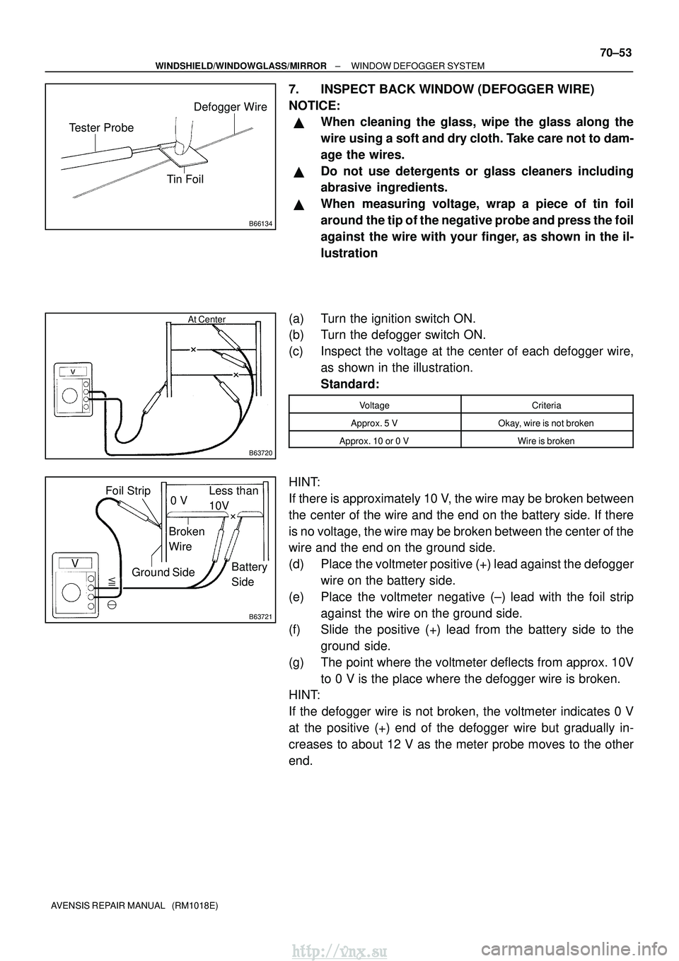
7. INSPECT BACK WINDOW (DEFOGGER WIRE)
NOTICE:
�When cleaning the glass, wipe the glass along the
wire using a soft and dry cloth. Take care not to dam-
age the wires.
�Do not use detergents or glass cleaners including
abrasive ingredients.
�When measuring voltage, wrap a piece of tin foil
around the tip of the negative probe and press the foil
against the wire with your finger, as shown in the il-
lustration
(a) Turn the ignition switch ON.
(b) Turn the defogger switch ON.
(c) Inspect the voltage at the center of each defogger wire, as shown in the illustration.
Standard:
VoltageCriteria
Approx. 5 VOkay, wire is not broken
Approx. 10 or 0 VWire is broken
HINT:
If there is approximately 10 V, the wire may be broken between
the center of the wire and the end on the battery side. If there
is no voltage, the wire may be broken between the center of the
wire and the end on the ground side.
(d) Place the voltmeter positive (+) lead against the defoggerwire on the battery side.
(e) Place the voltmeter negative (±) lead with the foil strip against the wire on the ground side.
(f) Slide the positive (+) lead from the battery side to the
ground side.
(g) The point where the voltmeter deflects from approx. 10V to 0 V is the place where the defogger wire is broken.
HINT:
If the defogger wire is not broken, the voltmeter indicates 0 V
at the positive (+) end of the defogger wire but gradually in-
creases to about 12 V as the meter probe moves to the other
end.
http://vnx.su
Page 1644 of 2234
B63722
Repair PointBroken
Wire
Masking Tape
B63723
B68374
1
2
35
B68374
1
2
35
70±54
±
WINDSHIELD/WINDOWGLASS/MIRROR WINDOW DEFOGGER SYSTEM
AVENSIS REPAIR MANUAL (RM1018E)
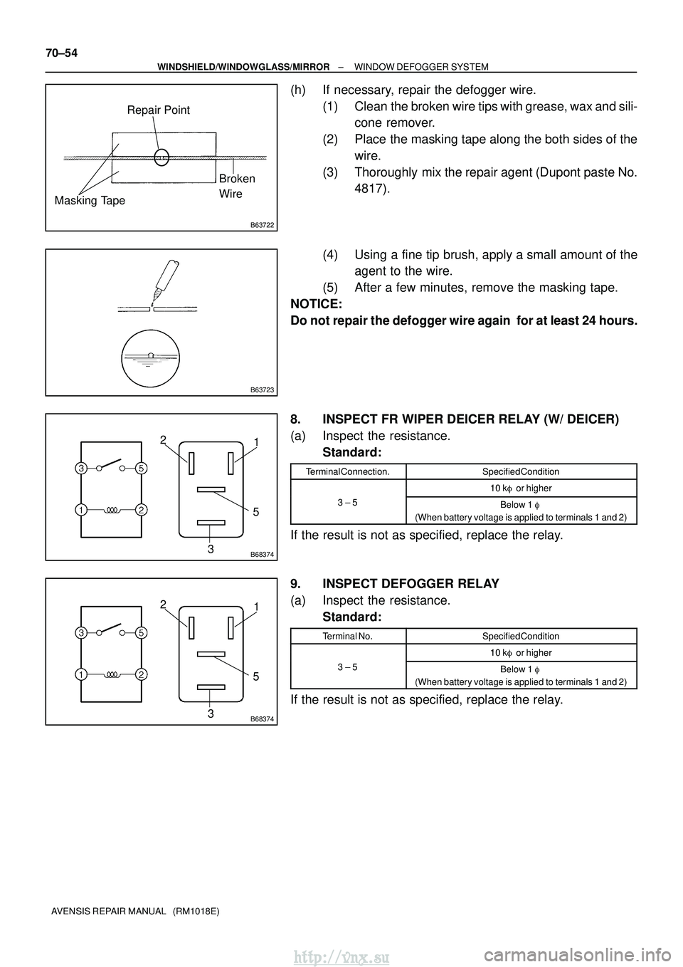
(h) If necessary, repair the defogger wire. (1) Clean the broken wire tips with grease, wax and sili-cone remover.
(2) Place the masking tape along the both sides of the wire.
(3) Thoroughly mix the repair agent (Dupont paste No. 4817).
(4) Using a fine tip brush, apply a small amount of the agent to the wire.
(5) After a few minutes, remove the masking tape.
NOTICE:
Do not repair the defogger wire again for at least 24 hours.
8. INSPECT FR WIPER DEICER RELAY (W/ DEICER)
(a) Inspect the resistance. Standard:
Terminal Connection.Specified Condition
10 k� or higher10 k� or higher
3 ± 5Below 1 �
(When battery voltage is applied to terminals 1 and 2)
If the result is not as specified, replace the relay.
9. INSPECT DEFOGGER RELAY
(a) Inspect the resistance. Standard:
Terminal No.Specified Condition
10 k� or higher10 k� or higher
3 ± 5Below 1 �
(When battery voltage is applied to terminals 1 and 2)
If the result is not as specified, replace the relay.
http://vnx.su
Page 1672 of 2234
B65859
Slide Motor
ClockwiseCounter±
clockwiseDriving Axis
B65859
Front Vertical
Motor
Clockwise
Counter±clockwise
Driving Axis
B65859
Lifter Motor
Clockwise
Counter±
clockwise
Driving Axis
72±8
±
SEAT FRONT POWER SEAT CONTROL SYSTEM
AVENSIS REPAIR MANUAL (RM1018E)
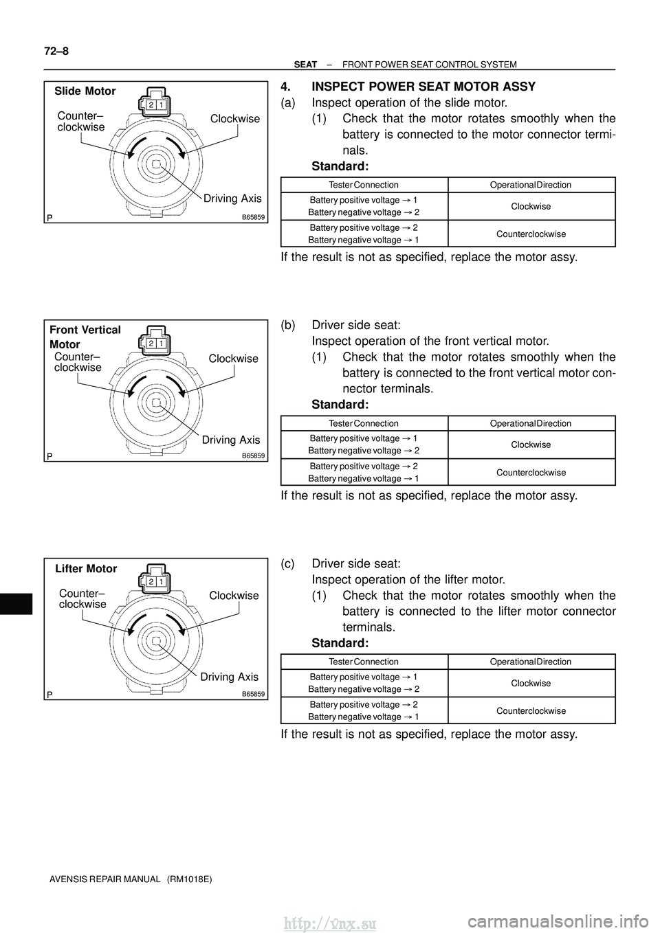
4. INSPECT POWER SEAT MOTOR ASSY
(a) Inspect operation of the slide motor. (1) Check that the motor rotates smoothly when the
battery is connected to the motor connector termi-
nals.
Standard:
Tester ConnectionOperational Direction
Battery positive voltage �1
Battery negative voltage �2Clockwise
Battery positive voltage �2
Battery negative voltage �1Counterclockwise
If the result is not as specified, replace the motor assy.
(b) Driver side seat:
Inspect operation of the front vertical motor.
(1) Check that the motor rotates smoothly when thebattery is connected to the front vertical motor con-
nector terminals.
Standard:
Tester ConnectionOperational Direction
Battery positive voltage �1
Battery negative voltage �2Clockwise
Battery positive voltage �2
Battery negative voltage �1Counterclockwise
If the result is not as specified, replace the motor assy.
(c) Driver side seat:
Inspect operation of the lifter motor.
(1) Check that the motor rotates smoothly when thebattery is connected to the lifter motor connector
terminals.
Standard:
Tester ConnectionOperational Direction
Battery positive voltage �1
Battery negative voltage �2Clockwise
Battery positive voltage �2
Battery negative voltage �1Counterclockwise
If the result is not as specified, replace the motor assy.
http://vnx.su
Page 1673 of 2234
B65859
Clockwise
Counter±
clockwise
Reclining Motor
Driving Axis
B65448
Clockwise
Driving Axis Counter±clockwise Lumbar Support
Adjuster Motor
±
SEAT FRONT POWER SEAT CONTROL SYSTEM
72±9
AVENSIS REPAIR MANUAL (RM1018E)
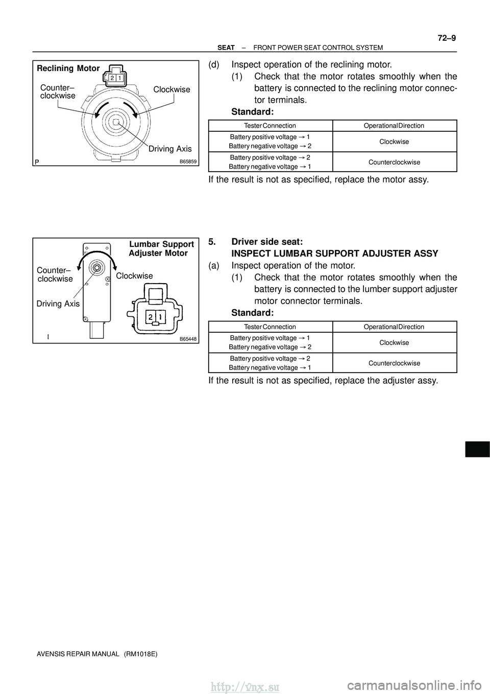
(d) Inspect operation of the reclining motor.
(1) Check that the motor rotates smoothly when thebattery is connected to the reclining motor connec-
tor terminals.
Standard:
Tester ConnectionOperational Direction
Battery positive voltage �1
Battery negative voltage �2Clockwise
Battery positive voltage �2
Battery negative voltage �1Counterclockwise
If the result is not as specified, replace the motor assy.
5. Driver side seat:
INSPECT LUMBAR SUPPORT ADJUSTER ASSY
(a) Inspect operation of the motor. (1) Check that the motor rotates smoothly when thebattery is connected to the lumber support adjuster
motor connector terminals.
Standard:
Tester ConnectionOperational Direction
Battery positive voltage �1
Battery negative voltage �2Clockwise
Battery positive voltage �2
Battery negative voltage �1Counterclockwise
If the result is not as specified, replace the adjuster assy.
http://vnx.su
Page 1675 of 2234
720J8±01
B57834
B57832
B57833
72±16
±
SEAT FRONT SEAT ASSEMBLY LH (MANUAL SEAT TYPE)
AVENSIS REPAIR MANUAL (RM1018E)
OVERHAUL
CAUTION:
�Wear safety gloves, because the cutting surface of the seatback frame and se\
at adjuster may
injure your hand.
�Work must be started more than 90 seconds after the ignition switch is turne\
d to the LOCK posi-
tion and the negative (±) terminal cable is disconnected from the b\
attery.
(The SRS is equipped with a back±up power source. If work is started within 90 se\
conds from
disconnecting the negative (±) terminal cable of the battery, the SRS may be deployed.)
HINT:
�The installation is in the reverse order of the removal. However, when there is a special point concern-
ing the installation, it is indicated.
�Use the same procedures on the RH side as on the LH side.
1. REMOVE FRONT SEAT ASSEMBLY LH
(a) Remove the headrest.
(b) Using a screwdriver, remove the 2 seat track covers.
HINT:
Tape the screwdriver tip before use.
(c) Disconnect the connectors under the seat.
(d) Remove the 4 bolts and seat.
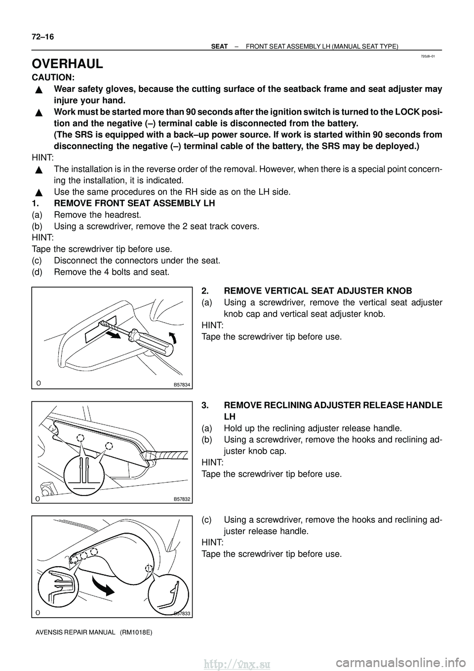
2. REMOVE VERTICAL SEAT ADJUSTER KNOB
(a) Using a screwdriver, remove the vertical seat adjusterknob cap and vertical seat adjuster knob.
HINT:
Tape the screwdriver tip before use.
3. REMOVE RECLINING ADJUSTER RELEASE HANDLE LH
(a) Hold up the reclining adjuster release handle.
(b) Using a screwdriver, remove the hooks and reclining ad- juster knob cap.
HINT:
Tape the screwdriver tip before use.
(c) Using a screwdriver, remove the hooks and reclining ad- juster release handle.
HINT:
Tape the screwdriver tip before use.
http://vnx.su