Page 1181 of 2234

D30815
(b)(a)
D26903
D26902
±
MANUAL TRANSMISSION/TRANSAXLE MANUAL TRANSAXLE ASSY (1CD±FTV)
41±39
AVENSIS REPAIR MANUAL (RM1018E)
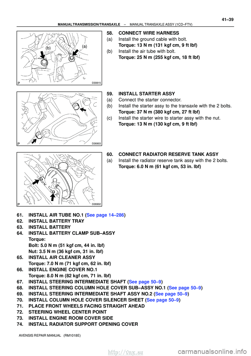
58. CONNECT WIRE HARNESS
(a) Install the ground cable with bolt.
Torque: 13 N �m (131 kgf� cm, 9 ft�lbf)
(b) Install the air tube with bolt. Torque: 25 N �m (255 kgf� cm, 18 ft�lbf)
59. INSTALL STARTER ASSY
(a) Connect the starter connector.
(b) Install the starter assy to the transaxle with the 2 bolts. Torque: 37 N �m (380 kgf� cm, 27 ft�lbf)
(c) Install the starter wire to starter assy with the nut. Torque: 13 N �m (130 kgf� cm, 9 ft�lbf)
60. CONNECT RADIATOR RESERVE TANK ASSY
(a) Install the radiator reserve tank assy with the 2 bolts. Torque: 6.0 N �m (61 kgf �cm, 53 in. �lbf)
61.INSTALL AIR TUBE NO.1 (See page 14±286)
62. INSTALL BATTERY TRAY
63. INSTALL BATTERY
64. INSTALL BATTERY CLAMP SUB±ASSY Torque:
Bolt: 5.0 N �m (51 kgf �cm, 44 in. �lbf)
Nut: 3.5 N� m (36 kgf�cm, 31 in. �lbf)
65. INSTALL AIR CLEANER ASSY
Torque: 7.0 N �m (71 kgf �cm, 62 in. �lbf)
66. INSTALL ENGINE COVER NO.1 Torque: 8.0 N �m (82 kgf �cm, 71 in. �lbf)
67.INSTALL STEERING INTERMEDIATE SHAFT (See page 50±9)
68.INSTALL STEERING COLUMN HOLE COVER SUB±ASSY NO.1 (See page 50±9)
69.INSTALL STEERING INTERMEDIATE SHAFT ASSY NO.2 (See page 50±9)
70.INSTALL COLUMN HOLE COVER SILENCER SHEET (See page 50±9)
71. PLACE FRONT WHEELS FACING STRAIGHT AHEAD
72. STEERING WHEEL CENTER POINT
73. INSTALL ENGINE ROOM COVER SIDE
74. INSTALL RADIATOR SUPPORT OPENING COVER
http://vnx.su
Page 1183 of 2234

410DS±01
D30478
Battery Clamp Sub±assyBattery Tray
Charcoal Canister Assy
Battery Carrier
Transmission Control Cable AssyClipAir Cleaner Assy
Hood Sub±assy
Cylinder Head Cover No.2 Starter Assy Back±up Lamp
SwitchConnector
Transverse Engine
Engine Mounting Bracket
Clip
Clip
Clip
Clip
37 (380, 27)
Starter Connector
Transverse Engine
Engine Mounting Insulator
52 (530, 38)
52 (530, 38)
Ground Cable
�
Gasket
7.0 (71, 62 in.� lbf)
Filler Plug
37 (380, 27)
23 (230, 17)
47 (479, 35)
N´m (kgf´cm, ft´lbf) : Specified torque
19 (195, 14)
13 (130, 9)
64 (653, 47)
64 (653, 47)
5.0 (51, 44 in.�lbf)
� Non±reusable part
5.0 (51, 44 in.� lbf)
14 (141, 10)
13 (133, 10)
13 (131, 9)
5.0 (51, 44 in.�lbf)
26 (260, 19)
25 (255, 18)
80 (816, 59)
26 (260, 19)
23 (230, 17)
Engine Room Cover Side
Radiator Support Opening Cover
40 (410, 30)
39 (400, 29)
Manual Transaxle Assy
64 (653, 47)
Battery
Clutch Release Cylinder Assy
±
MANUAL TRANSMISSION/TRANSAXLE MANUAL TRANSAXLE ASSY (1ZZ±FE/3ZZ±FE)
41±13
AVENSIS REPAIR MANUAL (RM1018E)
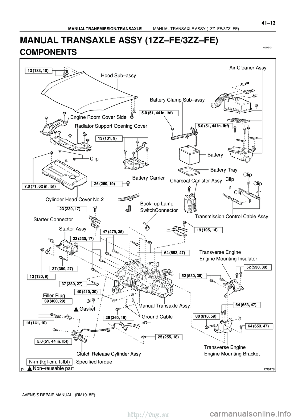
MANUAL TRANSAXLE ASSY (1ZZ±FE/3ZZ±FE)
COMPONENTS
http://vnx.su
Page 1191 of 2234

4206G±01
D30813
(a)
(a) (b)(b)
(a)
(b)
D30813
(a)
(a) (b)(b)
(a)
(b)
D26852
SST(s)
42±22
±
CLUTCH CLUTCH ACCUMULATOR ASSY (1CD±FTV)
AVENSIS REPAIR MANUAL (RM1018E)
REPLACEMENT
1. REMOVE BATTERY
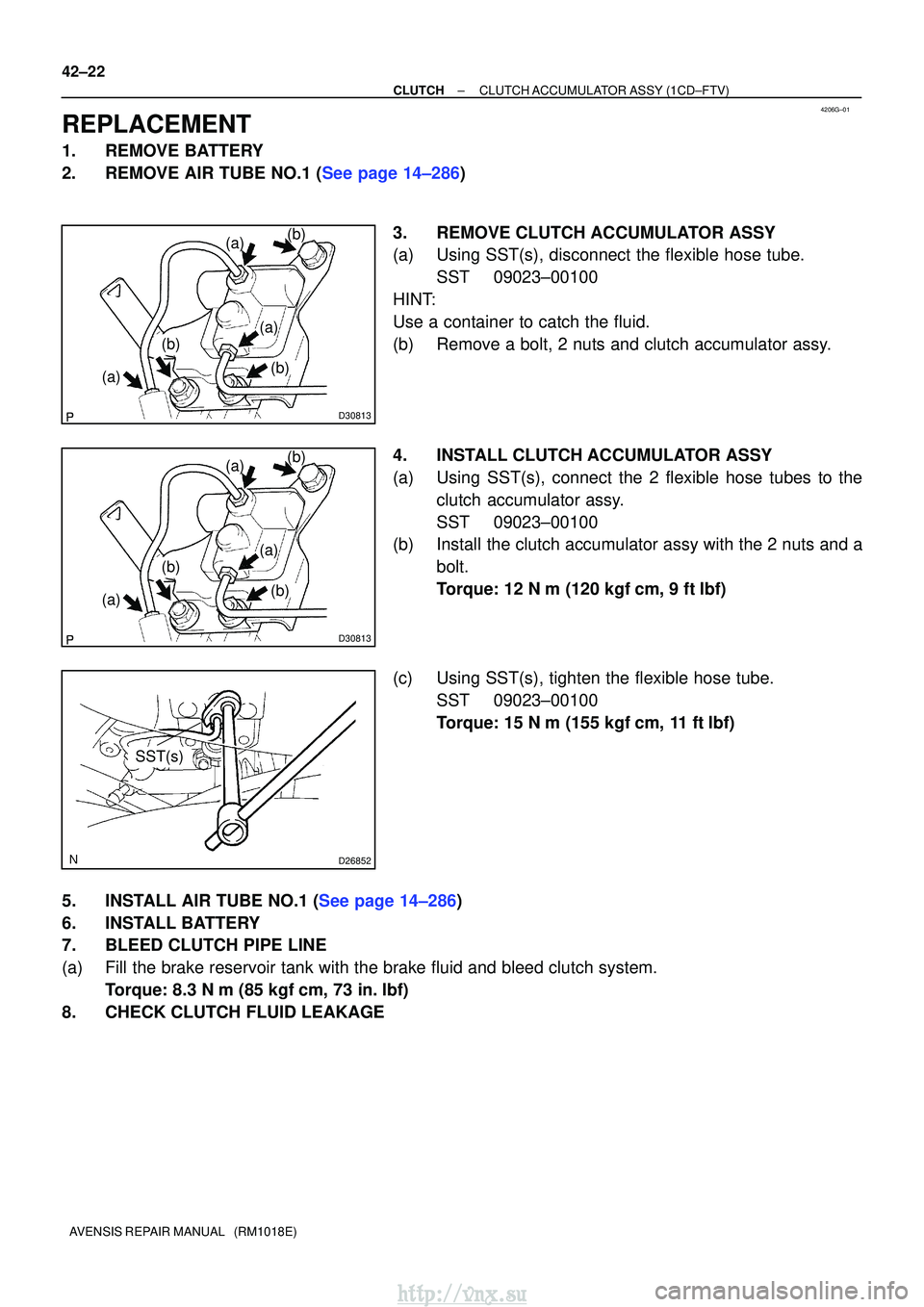
2.REMOVE AIR TUBE NO.1 (See page 14±286) 3. REMOVE CLUTCH ACCUMULATOR ASSY
(a) Using SST(s), disconnect the flexible hose tube.SST 09023±00100
HINT:
Use a container to catch the fluid.
(b) Remove a bolt, 2 nuts and clutch accumulator assy.
4. INSTALL CLUTCH ACCUMULATOR ASSY
(a) Using SST(s), connect the 2 flexible hose tubes to the clutch accumulator assy.
SST 09023±00100
(b) Install the clutch accumulator assy with the 2 nuts and a
bolt.
Torque: 12 N �m (120 kgf� cm, 9 ft�lbf)
(c) Using SST(s), tighten the flexible hose tube. SST 09023±00100
Torque: 15 N �m (155 kgf� cm, 11 ft�lbf)
5.INSTALL AIR TUBE NO.1 (See page 14±286)
6. INSTALL BATTERY
7. BLEED CLUTCH PIPE LINE
(a) Fill the brake reservoir tank with the brake fluid and bleed clutch syst\
em. Torque: 8.3 N �m (85 kgf �cm, 73 in. �lbf)
8. CHECK CLUTCH FLUID LEAKAGE
http://vnx.su
Page 1207 of 2234
4206F±01
D30487
SST(s)
1ZZ±FE/3ZZ±FE Engine Type:
1AZ±FE/1AZ±FSE Engine Type:SST(s)
D30814
±
CLUTCH CLUTCH RELEASE CYLINDER ASSY (MTM)
42±17
AVENSIS REPAIR MANUAL (RM1018E)
OVERHAUL
1. REMOVE BATTERY (1CD±FTV ENGINE TYPE)
2.REMOVE AIR TUBE NO.1 (1CD±FTV ENGINE TYPE) (See page 14±286)
3. DISCONNECT CLUTCH RELEASE CYLINDER TOFLEXIBLE HOSE TUBE (EXCEPT 1CD±FTV ENGINE
TYPE)
(a) Using SST(s), disconnect the flexible hose tube. SST 09023±00100
HINT:
Use a container to catch the fluid.
4. REMOVE CLUTCH ACCUMULATOR ASSY (1CD±FTV ENGINE TYPE)
(a) Disconnect the wire harness clamp.
(b) Using SST(s), disconnect the 2 flexible hose tubes. SST 09023±00100
HINT:
Use a container to catch the fluid.
(c) Remove the 2 nuts, bolt and clutch accumulator assy.
http://vnx.su
Page 1210 of 2234
D30814
D30487
SST(s)
1ZZ±FE/3ZZ±FE Engine Type:
1AZ±FE/1AZ±FSE Engine Type:SST(s)
42±20
±
CLUTCH CLUTCH RELEASE CYLINDER ASSY (MTM)
AVENSIS REPAIR MANUAL (RM1018E)
13. INSTALL CLUTCH ACCUMULATOR ASSY (1CD±FTV ENGINE TYPE)
(a) Install the clutch accumulator assy with the 2 nuts and
bolt.
Torque: 12 N� m (120 kgf�cm, 9 ft�lbf)
(b) Using SST(s), connect the 2 flexible hose tubes. SST 09023±00100
Torque: 15 N �m (155 kgf� cm, 11 ft�lbf)
(c) Connect the wire harness clamp.
14. CONNECT CLUTCH RELEASE CYLINDER TO FLEXIBLE HOSE TUBE (EXCEPT 1CD±FTV ENGINE
TYPE)
(a) Using SST(s), connect the flexible hose tube. SST 09023±00100
Torque: 15 N �m (155 kgf� cm, 11 ft�lbf)
15.INSTALL AIR TUBE NO.1 (1CD±FTV ENGINE TYPE) (See page 14±286)
16. INSTALL BATTERY (1CD±FTV ENGINE TYPE)
17. BLEED CLUTCH PIPE LINE
(a) Fill the brake reservoir tank with the brake fluid and bleed clutch syst\
em. Torque: 8.3 N �m (85 kgf �cm, 73 in. �lbf)
18. CHECK CLUTCH FLUID LEAKAGE
http://vnx.su
Page 1219 of 2234

5006Z±01
50±20
±
STEERING COLUMN POWER STEERING ECU ASSY
AVENSIS REPAIR MANUAL (RM1018E)
POWER STEERING ECU ASSY
REPLACEMENT
1.PRECAUTION (See page 60±1)
2.DISCONNECT BATTERY NEGATIVE TERMINAL (See page 60±1)
3.REMOVE INSTRUMENT CLUSTER FINISH PANEL GARNISH NO.1 (See page 71±11)
4.REMOVE INSTRUMENT CLUSTER FINISH PANEL GARNISH NO.2 (See page 71±11)
5.REMOVE INSTRUMENT PANEL REGISTER ASSY CTR (See page 71±11)
6.REMOVE STEERING COLUMN COVER LWR (See page 50±9)
7. REMOVE STEERING COLUMN COVER W/INSTRUMENT CLUSTER FINISH PANEL ASSY (See page 50±9)
8.REMOVE COMBINATION METER ASSY (See page 71±11)
9.REMOVE INSTRUMENT PANEL REGISTER ASSY NO.1 (See page 71±11)
10.REMOVE INSTRUMENT PANEL REGISTER ASSY NO.2(See page 71±11)
11.REMOVE GLOVE COMPARTMENT DOOR ASSY (See page 71±11)
12.REMOVE FRONT PILLAR GARNISH LH (See page 71±11)
13.REMOVE FRONT PILLAR GARNISH RH (See page 71±11)
14.DISCONNECT PASSENGER AIRBAG CONNECTOR(See page 71±11)
15. REMOVE INSTRUMENT PANEL SUB±ASSY UPPER W/INSTR PNL PASS L/DOOR AIR BAG
ASSY (See page 71±11)
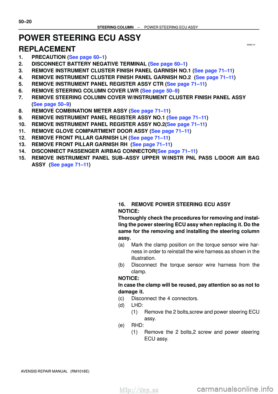
16. REMOVE POWER STEERING ECU ASSY
NOTICE:
Thoroughly check the procedures for removing and instal-
ling the power steering ECU assy when replacing it. Do the
same for the removing and installing the steering column
assy.
(a) Mark the clamp position on the torque sensor wire har-ness in order to reinstall the wire harness as shown in the
illustration.
(b) Disconnect the torque sensor wire harness from the clamp.
NOTICE:
In case the clamp will be reused, pay attention so as not to
damage it.
(c) Disconnect the 4 connectors.
(d) LHD: (1) Remove the 2 bolts,screw and power steering ECUassy.
(e) RHD: (1) Remove the 2 bolts,2 screw and power steeringECU assy.
http://vnx.su
Page 1221 of 2234
50±22
±
STEERING COLUMN POWER STEERING ECU ASSY
AVENSIS REPAIR MANUAL (RM1018E)
NOTICE:
�When reusing the clamp, check that there is no dam-
age on it.
�When reinstalling the wire harness, make sure there
is no twist in the harness or with other wire harness.
18. CONNECT BATTERY NEGATIVE TERMINAL
19.INSPECT SRS WARNING LIGHT (See page 05±1184)
20.PERFORM CALIBRATION OF TORQUE SENSOR ZERO POINT (See page 05±1045)
http://vnx.su
Page 1226 of 2234
5006Y±01
Screw Case
F44801
Torx Screw
F44804
Airbag Connector
Lock PartPull Out
F44805
Correct
Wrong
±
STEERING COLUMN STEERING COLUMN ASSY
50±9
AVENSIS REPAIR MANUAL (RM1018E)
OVERHAUL
1.PRECAUTION (See page 60±1)
2. INSPECT PLACE FRONT WHEELS FACING STRAIGHT AHEAD
3.DISCONNECT BATTERY NEGATIVE TERMINAL (See page 60±1)
4.REMOVE HORN BUTTON ASSY
NOTICE:
If the airbag connector is disconnected with the ignition
switch at ON, DTCs is recorded.
(a) Using a torx socket wrench, loosen the 2 torx screws untilthe groove along the screw circumference catches on the
screw case.
(b) Pull out the horn button assy from the steering wheel and disconnect the airbag connector.
(c) Disconnect the terminal.
NOTICE:
When removing the horn button assy, take care not to pull
the airbag wire harness.
CAUTION:
�When storing the horn button assy, keep the upper
surface of the horn button assy facing upward.
�Never disassemble the horn button assy.
http://vnx.su