Page 1236 of 2234

54.INSTALL INSTRUMENT PANEL AIR BAG ASSY (See page 60±54)
55. INSTALL COLUMN")
F44800
Marks
F44801
Torx ScrewScrew Case
±
STEERING COLUMN STEERING COLUMN ASSY
50±19
AVENSIS REPAIR MANUAL (RM1018E)
54.INSTALL INSTRUMENT PANEL AIR BAG ASSY (See page 60±54)
55. INSTALL COLUMN HOLE COVER SILENCER SHEET
56. PLACE FRONT WHEELS FACING STRAIGHT AHEAD
57.INSTALL SPIRAL CABLE SUB±ASSY (See page 60±26)
58. CENTER SPIRAL CABLE
(a) Check that the front wheels are facing straight ahead.
(b) Turn the cable counterclockwise by hand until it becomesharder to turn.
(c) Then rotate the cable clockwise about 2.5 turns to align the marks.
HINT:
The cable will rotate about 2.5 turns to either left or right of the
center.
59. INSTALL STEERING WHEEL ASSY
(a) Align matchmarks on the steering wheel and main shaft assembly.
(b) Install the steering wheel set nut. Torque: 50 N´m (510 kgf´cm, 37 ft´lbf)
(c) Connect the connector.
60. INSTALL HORN BUTTON ASSY
NOTICE:
�Never use airbag parts from another vehicle. When
replacing parts, replace with new ones.
�Make sure the horn button assy is installed with the
specified torque.
�If the horn button assy has been dropped, or there are
cracks, dents or other defects in the case or connec-
tor, replace the horn button assy with a new one.
�When installing the horn button assy, take care that
the wirings do not interfere with other parts and that
they are not pinched between other parts.
(a) Connect the terminal.
(b) Connect the airbag connector.
(c) Install the steering horn button assy after confirming that the circumference groove of the torx screws is caught on
the screw case.
(d) Using a torx socket wrench, torque the 2 screws. Torque: 8.8 N´m (90 kgf´cm, 78 in.´lbf)
61. STEERING WHEEL CENTER POINT
62. CONNECT BATTERY NEGATIVE TERMINAL
63.INSPECT SRS WARNING LIGHT(See page 05±1184)
64. PERFORM CALIBRATION OF TORQUE SENSOR ZERO POINT (ELECTRIC POWER STEERING) (See page 05±1045)
http://vnx.su
Page 1295 of 2234
 (+) (±) 1
2
3
0.39
0
I35437
Wire Harness Side:
Connector ºBº Connector ºAº
±
HEATER & AIR CONDITIONER AIR CONDITIONING SYSTEM
55")
550ZC±01
I35425
Dry Cell BatteryMPa
3.19
0.1 0.5 1.0 4.8 4.9 (V) (+) (±) 1
2
3
0.39
0
I35437
Wire Harness Side:
Connector ºBº Connector ºAº
±
HEATER & AIR CONDITIONER AIR CONDITIONING SYSTEM
55±3
AVENSIS REPAIR MANUAL (RM1018E)
ON±VEHICLE INSPECTION
1. INSPECT AIR CONDITIONER PRESSURE SENSOR
(a) Disconnect the pressure SW connector.
(b)Install the manifold gauge set (See page 55±38).
(c) Connect the positive (+) lead from the three 1.5 V dry cell
batteries to terminal 3 and negative (±) lead to terminal 1.
(d) Check the voltage between terminals 2 and 1 of pressure sensor.
Standard:
The voltage varies with on the refrigerant pressure as
shown in the chart.
2. INSPECT AIR CONDITIONING CONTROL ASSY
(a) Disconnect the connector from air conditioning control assy and inspect the connec\
tor on wire harness side, as shown in the table.
Symbols
(Terminal No.)ConditionSpecified condition
IG (B1) ± GND (B40)Ignition switch: LOCK � ON0 � 10 to 14 V
+B (B2) ± GND (B40)Always10 to 14 V
GND (B40) ± Body groundAlwaysContinuity
If circuit is not as specified, try replacing the air conditioning control\
assy with a new one. If the circuit is not
as specified, inspect the circuits connected to the other parts.
http://vnx.su
Page 1300 of 2234
I36092
LHD Models:REC
FRS
I36094
I36093
RHD Models: REC FRS
I36094
55±8
±
HEATER & AIR CONDITIONER AIR CONDITIONING SYSTEM
AVENSIS REPAIR MANUAL (RM1018E)
3. INSPECT RECI RCULATION DAMPER SERVO
SUB±ASSY (MANUAL AIR CONDITIONING)
(a) Inspect servomotor operation.
(1) Connect the positive (+) lead from the battery to ter-minal 3 and negative (±) lead to terminal 2, then
check that the arm turns to ºFRSº side smoothly.
(2) Connect the positive (+) lead from the battery to ter-
minal 3 and negative (±) lead to terminal 1, then
check that the arm turns to ºRECº side smoothly.
If operations are not as specified, replace the mode damper
servomotor.
http://vnx.su
Page 1301 of 2234
I30157
I30162
To ºMAX HOTº
To ºMAX COOLº
±
HEATER & AIR CONDITIONER AIR CONDITIONING SYSTEM
55±9
AVENSIS REPAIR MANUAL (RM1018E)
4. INSPECT AIRMIX DAMPER SERVO SUB±ASSY
(MANUAL AIR CONDITIONING)
(a) Inspect servomotor operation.
(1) Connect the positive (+) lead from the battery to ter-minal 4 and negative (±) lead to terminal 5, then
check that the arm turns to ºMAX COOLº side
smoothly.
(2) Connect the positive (+) lead from the battery to ter- minal 5 and negative (±) lead to terminal 4, then
check that the arm turns to ºMAX HOTº side
smoothly.
If operations are not as specified, replace the servomotor.
http://vnx.su
Page 1302 of 2234
I30157
I30116
To ºDEFºTo ºFACEº
55±10
±
HEATER & AIR CONDITIONER AIR CONDITIONING SYSTEM
AVENSIS REPAIR MANUAL (RM1018E)
5. INSPECT MODE DAMPER SERVO SUB±ASSY (MANUAL AIR CONDITIONING)
(a) Inspect servomotor operation.
(1) Connect the positive (+) lead from the battery to ter-minal 4 and negative (±) lead to terminal 5, then
check that the arm turns to ºDEFº side smoothly.
(2) Connect the positive (+) lead from the battery to ter-
minal 5 and negative (±) lead to terminal 4, then
check that the arm turns to ºFACEº side smoothly.
If operations are not as specified, replace the servomotor.
http://vnx.su
Page 1303 of 2234
��
E50650
I30145
40
30
20
10 8
6
4
2
0 ±30 ±20 ±10 0 10 20 30 50 60 70 80 40
Resistance (k
�)
Temperature (�C)
I30151
2
1
LHD
RHD
±
HEATER & AIR CONDITIONER AIR CONDITIONING SYSTEM
55±11
AVENSIS REPAIR MANUAL (RM1018E)
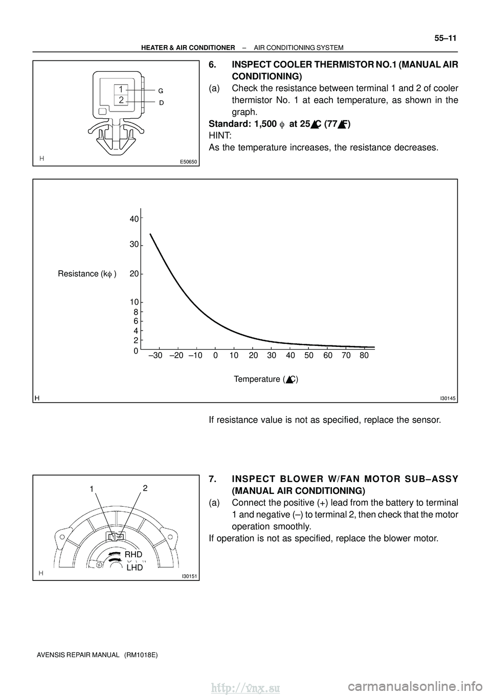
6. INSPECT COOLER THERMISTOR NO.1 (MANUAL AIR
CONDITIONING)
(a) Check the resistance between terminal 1 and 2 of cooler
thermistor No. 1 at each temperature, as shown in the
graph.
Standard: 1,500 � at 25�C (77� F)
HINT:
As the temperature increases, the resistance decreases.
If resistance value is not as specified, replace the sensor.
7. INSPECT BLOWER W/FAN MOTOR SUB±ASSY
(MANUAL AIR CONDITIONING)
(a) Connect the positive (+) lead from the battery to terminal
1 and negative (±) to terminal 2, then check that the motor
operation smoothly.
If operation is not as specified, replace the blower motor.
http://vnx.su
Page 1304 of 2234
E32993
55±12
±
HEATER & AIR CONDITIONER AIR CONDITIONING SYSTEM
AVENSIS REPAIR MANUAL (RM1018E)
8. INSPECT HEATER RELAY (M ANUAL AIR
CONDITIONING)
Terminal No.Specified condition
No continuity
3±5Less than 1 �
(When battery voltage applied to terminals 1 and 2.)
Less than 1 �
3±4No continuity
(When battery voltage applied to terminals 1 and 2.)
1±2Constant continuity
If continuity is not as specified, replace the rear cooler relay.
http://vnx.su
Page 1311 of 2234

Vehicle Side
SW
14
9
12
5
6
3")
I35431
Burner Motor
Glow Plug
Surface Sensor
Temp. Control Sensor
Flame Sensor 13
Power
Heater
ECU
Connector B Terminal L
of Alternator
Battery
Metering Pump
Fuse (20 A)
Vehicle Side
SW
14
9
12
5
6
3
4
1
2 R
BR
B±R
G
L±Y L
Y
L±W 5
1
6
2
7
3
8
4
W±B
R±G
R±B
Connector A
IG
W±R (*1)
Y±R (*2)R±L (*1)
R±Y (*2)
*1: TMC Made
*2: TMUK Made
55±16
±
HEATER & AIR CONDITIONER COMBUSTION TYPE POWER HEATER SYSTEM
AVENSIS REPAIR MANUAL (RM1018E)
2. DESCRIPTION OF DISPLAY AND BUTTONS
(a) AF: Current Value Malfunction (Blinking at current failure) Diag: DTC (Example: 064 Flame sensor break)
Memory Clear button: Deletion of faulty memory (Press both buttons together for longer than 2 se-
conds)
> Button: Scroll up of faulty memory (The past 5 codes can be stored.)\
< Button: Scroll down of faulty memory (The past 5 codes can be stored.\
)
3. FAULTY MEMORY
(a) The ECU is able to store up to 5 pieces of faulty memory. If it is full, the new data is written over F5.
4. WIRING DIAGRAM
http://vnx.su

3. INSPECT RECI RCULATION DAMPER SERVO
SU")

4. INSPECT AIRMIX DAMPER SERVO SUB±ASSY
(MANUAL AIR CONDITIONI")

5. INSPECT MODE DAMPER SERVO SUB±ASSY (MANUAL AIR CONDITIONING)
(a) In")

8. INSPECT HEATER RELAY (M ANUAL AIR
CONDITIONING)
Terminal No.Specified condition
No continuity
3±")