Page 1414 of 2234
6009P±04
H42622
H43002
±
SUPPLEMENTAL RESTRAINT SYSTEM HORN BUTTON ASSY
60±17
AVENSIS REPAIR MANUAL (RM1018E)
REPLACEMENT
1.PRECAUTION (See page 60±1)
2.DISCONNECT BATTERY NEGATIVE TERMINAL (See page 60±1)
3. REMOVE HORN BUTTON ASSY
(a) Place the front wheels facing straight ahead.
(b) Using a torx socket wrench (T30), loosen the 2 torxscrews until the groove along the screw circumference
catches on the screw case.
(c) Pull out the horn button assy from the steering wheel assy and support the horn button assy with one hand as shown
in the illustration.
NOTICE:
When removing the horn button assy, do not pull the airbag
wire harness.
(d) Using a screwdriver, disconnect the airbag connectors.
(e) Disconnect the horn connector.
(f) Remove the horn button assy.
http://vnx.su
Page 1416 of 2234
600JW±01
H40004
SST(s)
H40004
SST(s)
±
SUPPLEMENTAL RESTRAINT SYSTEM HORN BUTTON ASSY
60±19
AVENSIS REPAIR MANUAL (RM1018E)
DISPOSAL
HINT:
When scrapping a vehicle equipped with the SRS or disposing of a horn button\
assy, be sure to deploy the
airbag first in accordance with the procedure described below. If any abnormality occurs with the airbag de-
ployment, contact the SERVICE DEPT. of TOYOTA MOTOR SALES, U.S.A., INC.
CAUTION:
�Never dispose of the horn button assy that has an un-
deployed airbag.
�The airbag produces an extremely exploding sound
when it is deployed, so perform the operation out-
doors and where it will not create a nuisance to
nearby residents.
�When deploying the airbag, always use the specified
SST(s) (SRS Airbag Deployment Tool). Perform the
operation in a place away from electrical noise.
�When deploying the airbag, perform the operation at
least 10 m (33 ft) away from the horn button assy.
�The horn button assy is extremely hot when the air-
bag is deployed, so do not touch it for at least 30 min-
utes after deployment.
�Use gloves and safety glasses when handling the
horn button assy with the deployed airbag.
�Do not apply water, etc. to the horn button assy with
the deployed airbag.
�Always wash your hands with water after completing
the operation.
1. DISPOSE OF HORN BUTTON ASSY (WHEN SCRAPPING VEHICLE DEPLOYMENT METHOD)
HINT:
Prepare a battery as the power source to deploy the airbag.
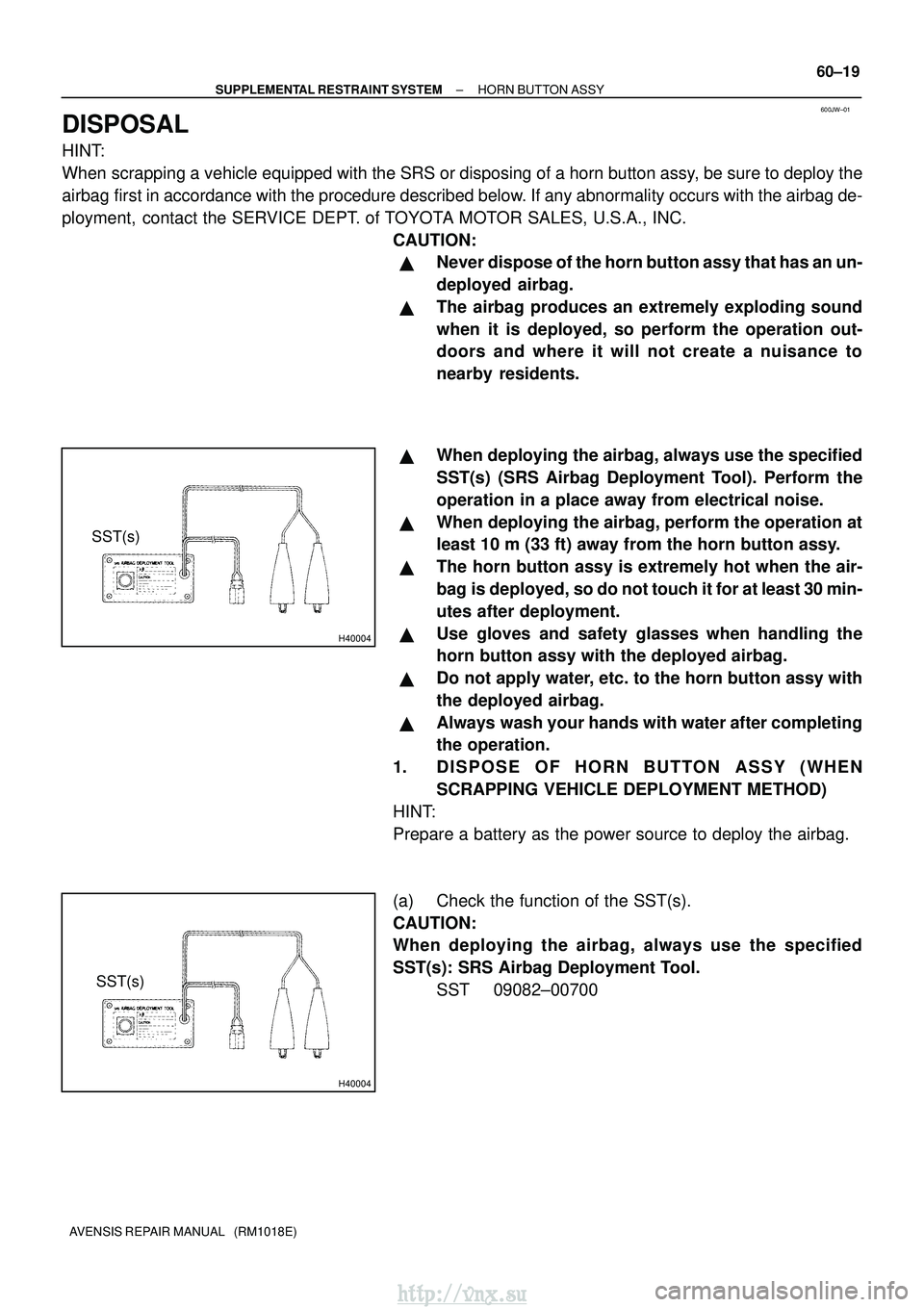
(a) Check the function of the SST(s).
CAUTION:
When deploying the airbag, always use the specified
SST(s): SRS Airbag Deployment Tool. SST 09082±00700
http://vnx.su
Page 1417 of 2234
H40005
Battery
SST(s)
H40006
SST(s)
H42625
H42626SST(s)
60±20
±
SUPPLEMENTAL RESTRAINT SYSTEM HORN BUTTON ASSY
AVENSIS REPAIR MANUAL (RM1018E)
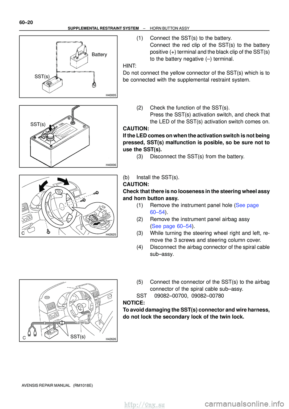
(1) Connect the SST(s) to the battery. Connect the red clip of the SST(s) to the battery
positive (+) terminal and the black clip of the SST(s)
to the battery negative (±) terminal.
HINT:
Do not connect the yellow connector of the SST(s) which is to
be connected with the supplemental restraint system.
(2) Check the function of the SST(s).Press the SST(s) activation switch, and check that
the LED of the SST(s) activation switch comes on.
CAUTION:
If the LED comes on when the activation switch is not being
pressed, SST(s) malfunction is posible, so be sure not to
use the SST(s). (3) Disconnect the SST(s) from the battery.
(b) Install the SST(s).
CAUTION:
Check that there is no looseness in the steering wheel assy
and horn button assy. (1)Remove the instrument panel hole (See page
60±54).
(2) Remove the instrument panel airbag assy (See page 60±54).
(3) While turning the steering wheel right and left, re-
move the 3 screws and steering column cover.
(4) Disconnect the airbag connector of the spiral cable sub±assy.
(5) Connect the connector of the SST(s) to the airbag connector of the spiral cable sub±assy.
SST 09082±00700, 09082±00780
NOTICE:
To avoid damaging the SST(s) connector and wire harness,
do not lock the secondary lock of the twin lock.
http://vnx.su
Page 1418 of 2234
H40007
10 m (33 ft) or more
Battery
SST(s)
H40005
Battery
SST(s)
±
SUPPLEMENTAL RESTRAINT SYSTEM HORN BUTTON ASSY
60±21
AVENSIS REPAIR MANUAL (RM1018E)
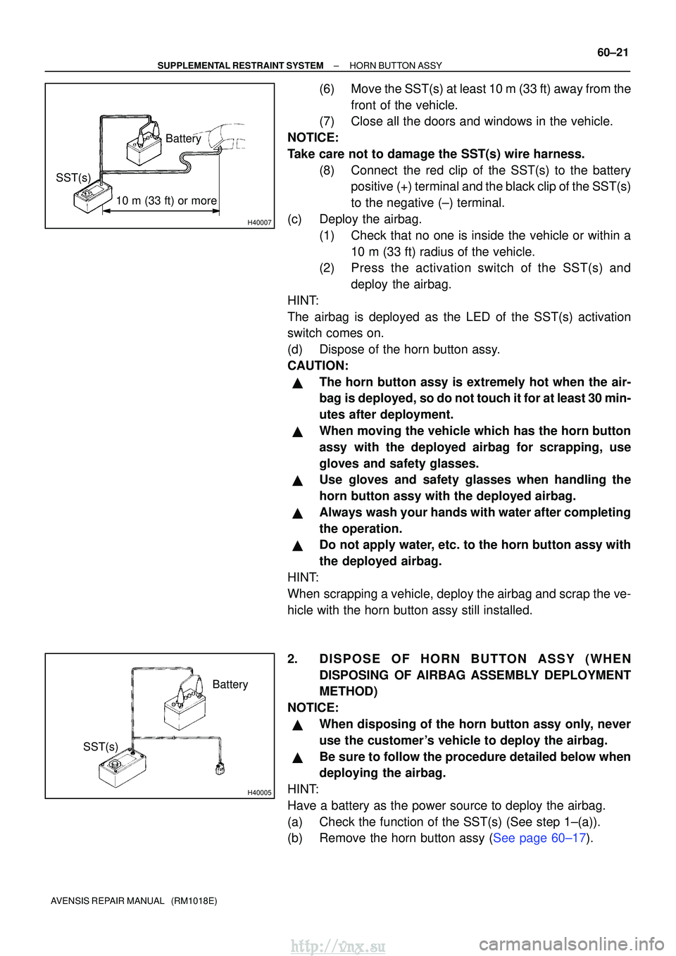
(6) Move the SST(s) at least 10 m (33 ft) away from the
front of the vehicle.
(7) Close all the doors and windows in the vehicle.
NOTICE:
Take care not to damage the SST(s) wire harness. (8) Connect the red clip of the SST(s) to the batterypositive (+) terminal and the black clip of the SST(s)
to the negative (±) terminal.
(c) Deploy the airbag. (1) Check that no one is inside the vehicle or within a10 m (33 ft) radius of the vehicle.
(2) Press the activation switch of the SST(s) and
deploy the airbag.
HINT:
The airbag is deployed as the LED of the SST(s) activation
switch comes on.
(d) Dispose of the horn button assy.
CAUTION:
�The horn button assy is extremely hot when the air-
bag is deployed, so do not touch it for at least 30 min-
utes after deployment.
�When moving the vehicle which has the horn button
assy with the deployed airbag for scrapping, use
gloves and safety glasses.
�Use gloves and safety glasses when handling the
horn button assy with the deployed airbag.
�Always wash your hands with water after completing
the operation.
�Do not apply water, etc. to the horn button assy with
the deployed airbag.
HINT:
When scrapping a vehicle, deploy the airbag and scrap the ve-
hicle with the horn button assy still installed.
2. DISPOSE OF HORN BUTTON ASSY (WHEN DISPOSING OF AIRBAG ASSEMBLY DEPLOYMENT
METHOD)
NOTICE:
�When disposing of the horn button assy only, never
use the customer's vehicle to deploy the airbag.
�Be sure to follow the procedure detailed below when
deploying the airbag.
HINT:
Have a battery as the power source to deploy the airbag.
(a) Check the function of the SST(s) (See step 1±(a)).
(b)Remove the horn button assy (See page 60±17).
http://vnx.su
Page 1419 of 2234
H40008
Wire Harness
Diameter
Stripped Wire Harness Section
H42627
L M
H42628
SST(s)
60±22
±
SUPPLEMENTAL RESTRAINT SYSTEM HORN BUTTON ASSY
AVENSIS REPAIR MANUAL (RM1018E)
CAUTION:
�When removing the horn button assy, work must be
started 90 seconds after the ignition switch is turned
to the ºLOCKº position and the negative (±) terminal
cable is disconnected from the battery.
�When storing the horn button assy, keep the upper
surface of the airbag deployment side facing upward.
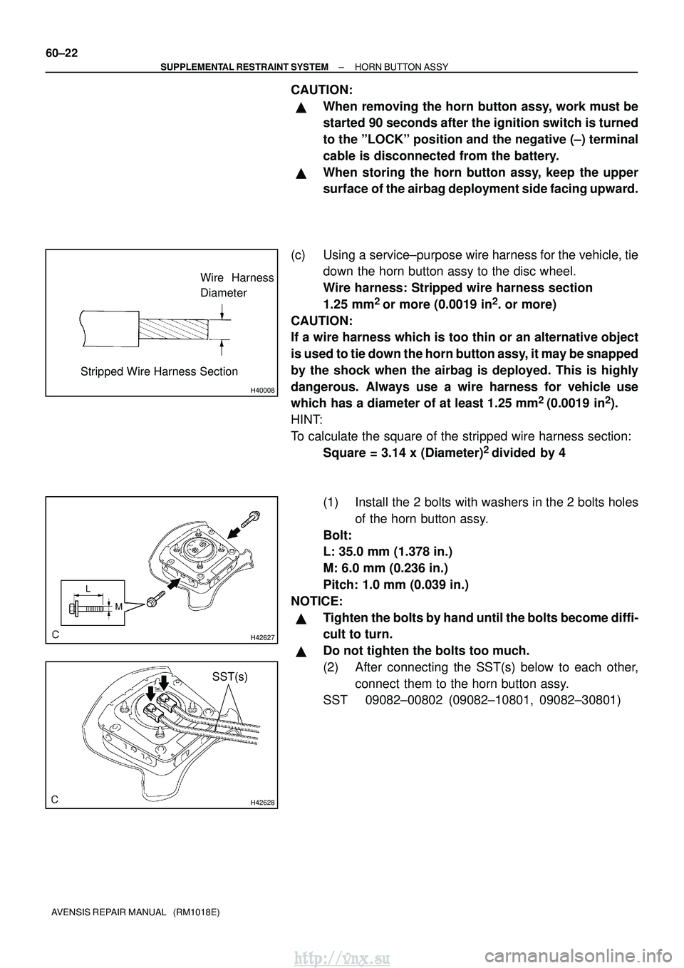
(c) Using a service±purpose wire harness for the vehicle, tie down the horn button assy to the disc wheel.
Wire harness: Stripped wire harness section
1.25 mm
2 or more (0.0019 in2. or more)
CAUTION:
If a wire harness which is too thin or an alternative object
is used to tie down the horn button assy, it may be snapped
by the shock when the airbag is deployed. This is highly
dangerous. Always use a wire harness for vehicle use
which has a diameter of at least 1.25 mm
2 (0.0019 in2).
HINT:
To calculate the square of the stripped wire harness section: Square = 3.14 x (Diameter)
2 divided by 4
(1) Install the 2 bolts with washers in the 2 bolts holes of the horn button assy.
Bolt:
L: 35.0 mm (1.378 in.)
M: 6.0 mm (0.236 in.)
Pitch: 1.0 mm (0.039 in.)
NOTICE:
�Tighten the bolts by hand until the bolts become diffi-
cult to turn.
�Do not tighten the bolts too much.
(2) After connecting the SST(s) below to each other, connect them to the horn button assy.
SST 09082±00802 (09082±10801, 09082±30801)
http://vnx.su
Page 1421 of 2234
H4263210 m (33 ft) or moreBattery
SST(s)
H42633Weight
X
Y
Y
H40013
Inner Diam.
Tires
(3 or More) Width
60±24
±
SUPPLEMENTAL RESTRAINT SYSTEM HORN BUTTON ASSY
AVENSIS REPAIR MANUAL (RM1018E)
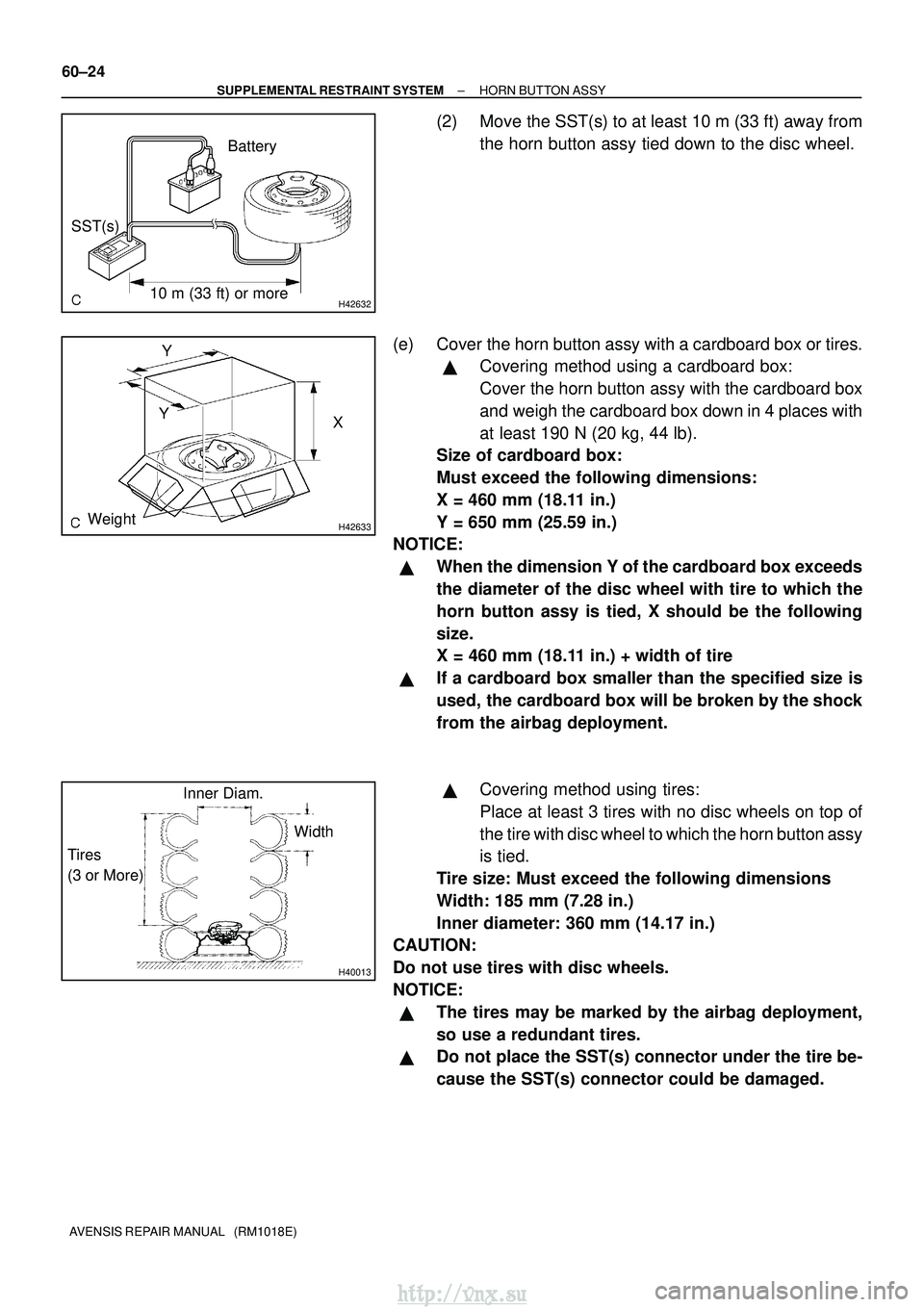
(2) Move the SST(s) to at least 10 m (33 ft) away from the horn button assy tied down to the disc wheel.
(e) Cover the horn button assy with a cardboard box or tires.
�Covering method using a cardboard box:
Cover the horn button assy with the cardboard box
and weigh the cardboard box down in 4 places with
at least 190 N (20 kg, 44 lb).
Size of cardboard box:
Must exceed the following dimensions:
X = 460 mm (18.11 in.)
Y = 650 mm (25.59 in.)
NOTICE:
�When the dimension Y of the cardboard box exceeds
the diameter of the disc wheel with tire to which the
horn button assy is tied, X should be the following
size.
X = 460 mm (18.11 in.) + width of tire
�If a cardboard box smaller than the specified size is
used, the cardboard box will be broken by the shock
from the airbag deployment.
�Covering method using tires:
Place at least 3 tires with no disc wheels on top of
the tire with disc wheel to which the horn button assy
is tied.
Tire size: Must exceed the following dimensions
Width: 185 mm (7.28 in.)
Inner diameter: 360 mm (14.17 in.)
CAUTION:
Do not use tires with disc wheels.
NOTICE:
�The tires may be marked by the airbag deployment,
so use a redundant tires.
�Do not place the SST(s) connector under the tire be-
cause the SST(s) connector could be damaged.
http://vnx.su
Page 1422 of 2234
H4263210 m (33 ft) or moreBattery
SST(s)
H42635
±
SUPPLEMENTAL RESTRAINT SYSTEM HORN BUTTON ASSY
60±25
AVENSIS REPAIR MANUAL (RM1018E)
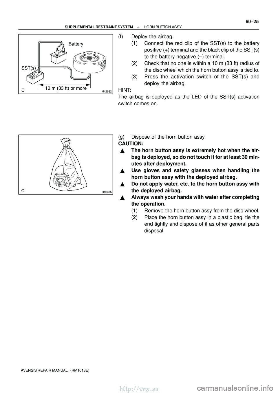
(f) Deploy the airbag.
(1) Connect the red clip of the SST(s) to the batterypositive (+) terminal and the black clip of the SST(s)
to the battery negative (±) terminal.
(2) Check that no one is within a 10 m (33 ft) radius of the disc wheel which the horn button assy is tied to.
(3) Press the activation switch of the SST(s) and
deploy the airbag.
HINT:
The airbag is deployed as the LED of the SST(s) activation
switch comes on.
(g) Dispose of the horn button assy.
CAUTION:
�The horn button assy is extremely hot when the air-
bag is deployed, so do not touch it for at least 30 min-
utes after deployment.
�Use gloves and safety glasses when handling the
horn button assy with the deployed airbag.
�Do not apply water, etc. to the horn button assy with
the deployed airbag.
�Always wash your hands with water after completing
the operation.
(1) Remove the horn button assy from the disc wheel.
(2) Place the horn button assy in a plastic bag, tie the end tightly and dispose of it as other general parts
disposal.
http://vnx.su
Page 1424 of 2234
600K4±01
H42660
H42661
H42665
60±54
±
SUPPLEMENTAL RESTRAINT SYSTEM INSTRUMENT PANEL AIR BAG ASSY
AVENSIS REPAIR MANUAL (RM1018E)
REPLACEMENT
1.PRECAUTION (See page 60±1)
2.DISCONNECT BATTERY NEGATIVE TERMINAL (See page 60±1)
3. REMOVE INSTRUMENT PANEL HOLE COVER
(a) Using a screwdriver, remove the 2 instrument panel hole cover. 4. REMOVE INSTRUMENT PANEL AIR BAG ASSY
(a) Using a screwdriver disconnect the airbag connector.
(b) Remove the 4 bolts, 2 nuts and the instrument panel air-bag assy.
5. INSTALL INSTRUMENT PANEL AIR BAG ASSY
(a) Install the instrument panel airbag assy.
(b) Connect the airbag connector.
(c) Install the 4 bolts and the 2 nuts. Torque: 18.0 N� m (184 kgf�cm, 13 ft�lbf)
(d) Install the instrument panel hole cover.
6.INSPECT INSTRUMENT PANEL AIR BAG ASSY (See page 60±11)
7.INSPECT SRS WARNING LIGHT (See page 05±1184)
http://vnx.su