Page 966 of 2234
19±28
±
STARTING & CHARGING CHARGING SYSTEM (1CD±FTV)
AVENSIS REPAIR MANUAL (RM1018E)
HINT:
�If the voltmeter reading is more than standard voltage, re-
place the voltage regulator.
�If the voltmeter reading is less than the standard voltage,
check the voltage regulator and generator as follows:
10. INSPECT CHARGING CIRCUIT WITH LOAD
(a) Keep the engine speed at 2,000 rpm, turn on the high beam headlights and\
turn the heater blower switch to the ºHIº position.
(b) Check the reading on the ammeter. Standard amperage: 30 A or more
HINT:
�If the ammeter reading is less than standard amperage, repair the genera\
tor.
�If the battery is fully charged, the indication will sometimes be less t\
han standard amperage.
http://vnx.su
Page 967 of 2234
190NP±01
19±4
±
STARTING & CHARGING CHARGING SYSTEM (1ZZ±FE/3ZZ±FE)
AVENSIS REPAIR MANUAL (RM1018E)
CHARGING SYSTEM (1ZZ±FE/3ZZ±FE)
PRECAUTION
1. Check that the battery cables are connected to the correct terminals.
2. Disconnect the battery cables when the battery is given a quick charge.
3. Do not perform tests with a high voltage insulation resistance tester.
4. Never disconnect the battery while the engine is running.
5. Check that the charging cable is tightened on terminal B of the generato\
r and the fuse box.
http://vnx.su
Page 968 of 2234

19±5
AVENSIS REPAIR MANUAL (RM1018")
190NQ±01
A81052
\b�����������A82936
Type A
Type B BlueWhite
Red
Green Dark
Clear or
light yellow
B00543
±
STARTING & CHARGING CHARGING SYSTEM (1ZZ±FE/3ZZ±FE)
19±5
AVENSIS REPAIR MANUAL (RM1018E)
ON±VEHICLE INSPECTION
1. CHECK BATTERY ELECTROLYTE LEVEL
(a) Check the electrolyte quantity of each cell.
(1) If the electrolyte is under the low level, replace the battery (or add di\
stilled water if possible) andcheck the charging system.
2. CHECK BATTERY VOLTAGE
(a) If it has not been 20 minutes since you drove the vehicleor since the engine was stopped, turn the ignition switch
and the electrical system (headlight, blower motor, rear
defogger etc.) to the on position for 60 seconds. This will
remove the surface charge on the battery.
(b) Turn off the ignition switch and the electrical systems.
(c) Measure the battery voltage between the negative (±) and positive (+) terminals of the battery.
Standard voltage: 12.5 to 12.9 V at 20 �C (68� F)
HINT:
If the voltage is less than specification, charge the battery.
(d) Check the indicator as shown in the illustration.
HINT:
Indicator colorConditionType AType BCondition
GreenBlueOK
DarkWhiteCharging necessary
Clear or light yellowRedReplace
3. CHECK BATTERY TERMINALS, FUSIBLE LINK AND FUSES
(a) Check that the battery terminals are not loosened or corroded.
(b) Check the fusible links, high±current fuses and regular fuses.
4. INSPECT DRIVE BELT
(a) Visually check the belt for excessive wear, frayed cordsetc.
HINT:
�If any defect found, replace the drive belt.
�Cracks on the rib side of a belt are considered acceptable.
If the belt has chunks missing from the ribs, it should be
replaced.
http://vnx.su
Page 969 of 2234

AVENSIS REPAIR MANUAL (RM1018E)
(b) Check that it fit")
B00540
A75980
Disconnect Wire
from Terminal B
Generator
Voltmeter
Battery Ammeter
19±6
±
STARTING & CHARGING CHARGING SYSTEM (1ZZ±FE/3ZZ±FE)
AVENSIS REPAIR MANUAL (RM1018E)
(b) Check that it fits properly in the ribbed grooves.
HINT:
Check with your hand to confirm that the belt has not slipped out
of the groove on the bottom of the pulley.
5. VISUALLY CHECK GENERATOR WIRING
(a) Check that the wiring is in good condition.
6. LISTEN FOR ABNORMAL NOISES FROM GENERATOR
(a) Check that there is no abnormal noise from the generator while the engin\
e is running.
7. INSPECT CHARGE WARNING LIGHT CIRCUIT
(a) Turn the ignition switch ON. Check that the charge warning light comes on\
.
(b) Start the engine and check that the light goes off.
HINT:
If the light does not operate as specified, troubleshoot the charge warn\
ing light circuit. 8. INSPECT CHARGING CIRCUIT WITHOUT LOAD
(a) According to the following procedure, connect an amme-ter and voltmeter as shown in the illustration.
(1) Disconnect the wire from terminal B of the generatorand connect it to the negative (±) lead of the amme-
ter.
(2) Connect the positive (+) lead of the ammeter to ter- minal B of the generator
(3) Connect the positive (+) lead of the voltmeter to ter-
minal B of the generator.
(4) Ground the negative (±) lead of the voltmeter.
(b) Check the charging circuit. (1) Keep the engine speed at 2,000 rpm, check thereading on the ammeter and voltmeter.
Standard amperage: 10 A or less
Standard voltage: 12.9 to 14.9 V
HINT:
�If the voltmeter reading is more than standard voltage, re-
place the voltage regulator.
�If the voltmeter reading is less than the standard voltage,
check the voltage regulator and generator as follows:
9. INSPECT CHARGING CIRCUIT WITH LOAD
(a) Keep the engine speed at 2,000 rpm, turn on the high beam headlights and\
turn the heater blower switch to the ºHIº position.
(b) Check the reading on the ammeter. Standard amperage: 30 A or more
HINT:
�If the ammeter reading is less than standard amperage, repair the genera\
tor.
�If the battery is fully charged, the indication will sometimes be less t\
han standard amperage.
http://vnx.su
Page 975 of 2234
![TOYOTA AVENSIS 2003 Service Repair Manual 190JE±02
A82619
Light Lightning Time
Water Temperature
±20 0 28
0
±4 32 ( �F)
(
� C)
82.4
(sec.)
10
3
1
A72562
Pre±heating Time (sec)Battery Voltage [V]
A80155
After Glow Time
Water Temperature 68](/manual-img/14/57444/w960_57444-974.png "TOYOTA AVENSIS 2003 Service Repair Manual 190JE±02
A82619
Light Lightning Time
Water Temperature
±20 0 28
0
±4 32 ( �F)
(
� C)
82.4
(sec.)
10
3
1
A72562
Pre±heating Time (sec)Battery Voltage [V]
A80155
After Glow Time
Water Temperature 68")
190JE±02
A82619
Light Lightning Time
Water Temperature
±20 0 28
0
±4 32 ( �F)
(
� C)
82.4
(sec.)
10
3
1
A72562
Pre±heating Time (sec)Battery Voltage [V]
A80155
After Glow Time
Water Temperature 68 104 (
�F)
020 40(
�C)
(sec.)
1
19±30
±
STARTING & CHARGING PRE±HEATING SYSTEM (1CD±FTV)
AVENSIS REPAIR MANUAL (RM1018E)
PRE±HEATING SYSTEM (1CD±FTV)
ON±VEHICLE INSPECTION
NOTICE:
Turn the ignition switch OFF for 60 seconds before performing the followi\
ng inspections. 1. INSPECT LIGHTING DURATION OF GLOW INDICA-TOR LIGHT
(a) Turn the ignition switch ON, and measure the lighting duration.
Light lighting duration: Refer to the chart graph
2. INSPECT PRE±HEATING
(a) Turn the ignition switch ON, measure how long it takes to the battery voltage is applied to the glow plugs.
SST 09082±00030, 09083±00150
Pre±Heating time:
Engine coolant temperaturePre±Heating time
40 �C or more1 sec
40 �C or lessRefer to the chart graph
(15 sec at the longest)
(b) Turn the ignition switch STA, check that the battery volt- age applied to the glow plugs.
SST 09082±00030, 09083±00150
(c) While cranking the engine, measure how long it takes to
the battery voltage is applied to the glow plugs.
SST 09082±00030, 09083±00150
Pre±Heating time:
Engine coolant temperaturePre±Heating time
40 �C or more1 sec
40 �C or lessRefer to the chart graph
(15 sec at the longest)
3. INSPECT AFTER GLOW TIME
(a) After the engine starting, measure how long it takes to the battery voltage is applied to the terminal SREL of the
ECM.
After glow time: Refer to the chart graph
http://vnx.su
Page 977 of 2234
190JF±02
�� ��
A34838
19±32
±
STARTING & CHARGING PRE±HEATING SYSTEM (1CD±FTV)
AVENSIS REPAIR MANUAL (RM1018E)
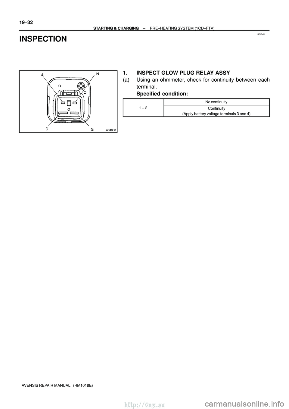
INSPECTION
1. INSPECT GLOW PLUG RELAY ASSY
(a) Using an ohmmeter, check for continuity between each terminal.
Specified condition:
No continuity
1 ± 2Continuity
(Apply battery voltage terminals 3 and 4)
http://vnx.su
Page 978 of 2234
190NJ±01
A77898
A77899
(a)
(a)
(a)(c)
(d)
Terminal Cap Cover
A77900
A77901
19±12
±
STARTING & CHARGINGSTARTER ASSY(1AZ±FE/1AZ±FSE)
AVENSIS REPAIR MANUAL (RM1018E)
STARTER ASSY(1AZ±FE/1AZ±FSE)
REPLACEMENT
1.REMOVE RADIATOR SUPPORT OPENING COVER (See page 10±26)
2. REMOVE BATTERY CLAMP SUB±ASSY
3. REMOVE BATTERY
4. REMOVE BATTERY TRAY 5. REMOVE BATTERY CARRIER
(a) Remove the 4 bolts, and then remove the battery carrier.
6. REMOVE STARTER ASSY
(a) Remove the 3 wire harness clamps.
(b) Open the terminal cap cover.
(c) Remove the nut and disconnect the starter wire.
(d) Disconnect the starter connector.
(e) Remove the 2 bolts, and then remove the starter.
(f) Remove the bolt, and then remove the wire harnessclamp bracket.
http://vnx.su
Page 979 of 2234
±
STARTING & CHARGING STARTER ASSY (1AZ±FE/1AZ±FSE)
19±13
AVENSIS REPAIR MANUAL (RM1018E)
7. INSTALL STARTER ASSY
(a) Install the wire harness clamp bracket with the bolt.
Torque: 8.4 N �m (86 kgf �cm, 74 in. �lbf)
(b) Install the starter with the 2 bolts. Torque: 37 N �m (380 kgf� cm, 28 ft�lbf)
(c) Connect the starter connector.
(d) Connect the starter wire with the nut. Torque: 9.8 N �m (100 kgf� cm, 7 ft�lbf)
(e) Close the terminal cap cover.
(f) Install the 3 wire harness clamps.
8. INSTALL BATTERY CARRIER Torque: 13 N �m (131 kgf� cm, 9 ft�lbf)
9. INSTALL BATTERY TRAY
10. INSTALL BATTERY
11. INSTALL BATTERY CLAMP SUB±ASSY Torque:
5.0 N�m (51 kgf �cm, 44 in. �lbf) for bolt
3.6 N� m (36 kgf �cm, 31 in. �lbf) for nut
5.4 N� m (55 kgf �cm, 48 in. �lbf) for terminal
12. INSTALL RADIATOR SUPPORT OPENING COVER
http://vnx.su


AVENSIS REPAIR MANUAL (RM1018E)
CHARGING SYSTEM (1ZZ±FE/3ZZ±FE)
PRECAUTION
1. Check that the battery cables are connected t")

(a)
(a)(c)
(d)
Terminal Cap Cover
A77900
A77901
19±12
±
STARTING & CHARGINGSTARTER ASSY(1AZ±FE/1AZ±FSE)
AVENSIS REPAIR MANUAL (RM1018E)
STARTER ASSY(1AZ±FE/1AZ±FSE)")