Page 3705 of 4179

COMBINATION METERS
DI-27
C
D
E
F
G
H
I
J
L
MA
B
DI
The Fuel Gauge Pointer Fluctuates, Indicator Wrong Value or VariesEKS00EHG
1. CHECK FUEL GAUGE FLUCTUATION
Test drive vehicle to see if gauge fluctuates only during driving and just before or soon after stopping.
Does the indication value vary only during driving and just before or soon after stopping?
YES >> The pointer fluctuation may be caused by fuel level change in the fuel tank. Condition is normal.
NO >> Ask the customer about the situation when the symptom occurs in detail, and perform the trouble
diagnosis.
The Fuel Gauge Does Not Move to FULL positionEKS00EHH
1. QUESTION 1
Does it take a long time for the pointer to move to FULL position?
YES or NO
YES >> GO TO 2.
NO >> GO TO 3.
2. QUESTION 2
Was the vehicle fueled with the ignition switch ON?
YES or NO
YES >> Be sure to fuel the vehicle with the ignition switch OFF. Otherwise, it will take a long time to move
to FULL position because of the characteristic of the fuel gauge.
NO >> GO TO 3.
3. QUESTION 3
Is the vehicle parked on an incline?
YES or NO
YES >> Check the fuel level indication with vehicle on a level surface.
NO >> GO TO 4.
4. QUESTION 4
During driving, does the fuel gauge pointer move gradually toward EMPTY position?
YES or NO
YES >> Check fuel level sensor unit. Refer to DI-30, "FUEL LEVEL SENSOR UNIT CHECK/GASOLINE
ENGINE MODELS" or DI-30, "FUEL LEVEL SENSOR UNIT CHECK/DIESEL ENGINE MOD-
ELS" .
NO >> The float arm may interfere or bind with any of the components in the fuel tank.
Page 3708 of 4179

DI-30
COMBINATION METERS
Electrical Components InspectionEKS00INH
FUEL LEVEL SENSOR UNIT CHECK/GASOLINE ENGINE MODELS
For removal, refer to FL-4, "FUEL LEVEL SENSOR UNIT, FUEL FILTER AND FUEL PUMP ASSEMBLY" for
Gasoline engine models.
Fuel level sensor unit
Check the resistance between terminals 1 and 4.
*1 and *2: When float rod is in contact with stopper.
Sub fuel level sensor unit
Check the resistance between terminals 1 and 3.
*1 and *2: When float rod is in contact with stopper.
FUEL LEVEL SENSOR UNIT CHECK/DIESEL ENGINE MODELS
For removal, refer to FL-19, "FUEL LEVEL SENSOR UNIT" for Diesel engine models.
Fuel level sensor unit
Check the resistance between terminals 1 and 4.
*1 and *2: When float rod is in contact with stopper.
Sub fuel level sensor unit
Check the resistance between terminals 1 and 3.
*1 and *2: When float rod is in contact with stopper.Ohmmeter
Float position mm (in) Resistance valueΩ
(+) (−)
41*1 Full 24 (2.36) Approx. 5
*2 Empty 167 (6.57) Approx. 80
SKIA0904E
Ohmmeter
Float position mm (in) Resistance valueΩ
(+) (−)
13*1 Full 35 (1.50) Approx. 1
*2 Empty 186 (6.38) Approx. 40
SKIA1032E
Ohmmeter
Float position mm (in) Resistance valueΩ
(+) (−)
14*1 Full 24 (0.94) Approx. 5
*2 Empty 170 (6.69) Approx. 80
SKIA0909E
Ohmmeter
Float position mm (in) Resistance valueΩ
(+) (−)
13*1 Full 34 (1.34) Approx. 1
*2 Empty 186 (7.32) Approx. 40
SKIA0910E
Page 3728 of 4179
DI-50
WARNING LAMPS
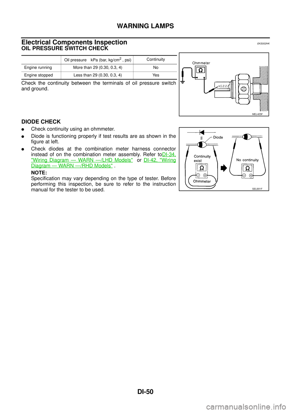
Electrical Components InspectionEKS002HK
OIL PRESSURE SWITCH CHECK
Check the continuity between the terminals of oil pressure switch
and ground.
DIODE CHECK
�Check continuity using an ohmmeter.
�Diode is functioning properly if test results are as shown in the
figure at left.
�Check diodes at the combination meter harness connector
instead of on the combination meter assembly. Refer toDI-34,
"Wiring Diagram — WARN —/LHD Models" or DI-42, "Wiring
Diagram — WARN —/RHD Models" .
NOTE:
Specification may vary depending on the type of tester. Before
performing this inspection, be sure to refer to the instruction
manual for the tester to be used.
Oil pressure kPa (bar, kg/cm2 , psi)Continuity
Engine running More than 29 (0.30, 0.3, 4) No
Engine stopped Less than 29 (0.30, 0.3, 4) Yes
MEL425F
SEL901F
Page 3752 of 4179
WW-12
FRONT WIPER AND WASHER SYSTEM
Removal and Installation for Washer Nozzle EKS0032U
REMOVAL
1. Push washer nozzle pawl toward engine hood to pull out.
INSTALLATION
1. After connecting washer hose, press nozzle from cowl top cover surface.
2. Assemble nozzle and socket.
3. Adjust nozzle injection position.
Inspection for Washer Nozzle EKS0032V
CHECK VALVE
�Blow air in the injection direction, and check that air flows only
one way. Make sure that the reverse direction (inhale) is not
possible.
Removal and Installation for Wiper and Washer Switch EKS0032W
REMOVAL
1. Remove steering column cover.
2. Remove wiper washer switch connector.
3. Remove two screws then remove wiper washer switch from the
spiral cable.
INSTALLATION
Installation is in the reverse order of removal.
PKIA9740E
PKIA9741E
SKIA0018E
Page 3782 of 4179
![NISSAN X-TRAIL 2003 Service Repair Manual LAN-4
[CAN]
CAN COMMUNICATION
CAN COMMUNICATIONPFP:23710
System DescriptionEKS001U3
CAN (Controller Area Network) is a serial communication line for real time application. It is an on-vehicle mul-
t](/manual-img/5/57404/w960_57404-3781.png "NISSAN X-TRAIL 2003 Service Repair Manual LAN-4
[CAN]
CAN COMMUNICATION
CAN COMMUNICATIONPFP:23710
System DescriptionEKS001U3
CAN (Controller Area Network) is a serial communication line for real time application. It is an on-vehicle mul-
t")
LAN-4
[CAN]
CAN COMMUNICATION
CAN COMMUNICATIONPFP:23710
System DescriptionEKS001U3
CAN (Controller Area Network) is a serial communication line for real time application. It is an on-vehicle mul-
tiplex communication line with high data communication speed and excellent error detection ability. Many elec-
tronic control units are equipped onto a vehicle, and each control unit shares information and links with other
control units during operation (not independent). In CAN communication, control units are connected with 2
communication lines (CAN H line, CAN L line) allowing a high rate of information transmission with less wiring.
Each control unit transmits/receives data but selectively reads required data only.
CAN Communication UnitEKS00EGL
Go to CAN system, when selecting your CAN system type from the following table.
TYPE 1
System diagram
Input/output signal chart
T: Transmit R: Receive Body typeWagon
Axle4WD
Engine QR20DE/QR25DE QR25DE YD22DDTi QR25DE
Transmission M/T A/T M/T A/T
Brake control ABS ESP
CAN system type 1 2 3 4 5
CAN system trouble diagnosisLAN-9
LAN-25LAN-50LAN-68LAN-86
PKIA6458E
Signals ECMABS actuator and
electric unit
(control unit)4WD control unit Combination meter
Stop lamp switch signal T R
Engine speed signal T R R
Engine coolant temperature signal T R
Accelerator pedal position signal T R
A/C compressor feedback signal T R
Vehicle speed signalTRR
RT
Page 3783 of 4179
CAN COMMUNICATION
LAN-5
[CAN]
C
D
E
F
G
H
I
J
L
MA
B
LAN
TYPE 2
System diagram
Input/output signal chart
T: Transmit R: Receive ABS warning lamp signal T R
4WD warning lamp signalTR
4WD mode indicator lamp signal T R
Parking brake switch signalRT
MI signal T RSignals ECMABS actuator and
electric unit
(control unit)4WD control unit Combination meter
PKIA6457E
Signals ECM TCMABS actuator
and electric unit
(control unit)4WD control
unitCombination
meter
Stop lamp switch signalRT
TR
P·N range signal R T
A/T position indicator lamp signal T R
Overdrive control switch signal R T
O/D OFF indicator signal T R
Closed throttle position signal T R
Wide open throttle position signal T R
Engine speed signal T R R
Engine coolant temperature signal TR
Accelerator pedal position signal T R
Output shaft revolution signal R T
A/C compressor feedback signal TR
Vehicle speed signalTRR
RT
ABS warning lamp signal T R
Page 3784 of 4179
LAN-6
[CAN]
CAN COMMUNICATION
TYPE 3/TYPE4
System diagram
Input/output signal chart
T: Transmit R: Receive 4WD warning lamp signalTR
4WD mode indicator lamp signalTR
Parking brake switch signalRT
MI signal TR
Engine A/T integrated control signalTR
RT
A/T self-diagnosis signal R TSignals ECM TCMABS actuator
and electric unit
(control unit)4WD control
unitCombination
meter
PKIA9634E
Signals ECMESP/TCS/ABS
control unitSteering angle
sensor4WD control
unitCombination
meter
Stop lamp switch signal T R
Engine speed signal T R R R
Engine coolant temperature signal TR
Accelerator pedal position signal T R R
A/C switch signal*
1RT
A/C compressor feedback signal*
2TR
Vehicle speed signalTRR
RT
ABS warning lamp signal T R
Brake warning lamp signal T R
SLIP indicator lamp signal T R
ESP OFF indicator lamp signal T R
4WD warning lamp signalTR
4WD mode indicator lamp signalTR
Parking brake switch signalRT
Page 3785 of 4179
CAN COMMUNICATION
LAN-7
[CAN]
C
D
E
F
G
H
I
J
L
MA
B
LAN
*1: YD engine models only
*2: QR engine models only
TYPE 5
System diagram
Input/output signal chart
T: Transmit R: Receive MI signal TR
Glow indicator lamp signal*
1TR
Steering angle sensor signal R TSignals ECMESP/TCS/ABS
control unitSteering angle
sensor4WD control
unitCombination
meter
PKIA9635E
Signals ECM TCMESP/TCS/
ABS control
unitSteering
angle sensor4WD control
unitCombination
meter
Stop lamp switch signalRT
TR
P·N range signal R T
A/T position indicator lamp signal T R R
O/D OFF indicator signal T R
Overdrive control switch signal R T
Closed throttle position signal T R
Wide open throttle position signal T R
Engine speed signal T R R R
Engine coolant temperature signal TR
Accelerator pedal position signal T R R
Output shaft revolution signal R T
A/C compressor feedback signal TR
Vehicle speed signalTRR
RT
ABS warning lamp signal T R
Brake warning lamp signal T R

![NISSAN X-TRAIL 2003 Service Repair Manual CAN COMMUNICATION
LAN-5
[CAN]
C
D
E
F
G
H
I
J
L
MA
B
LAN
TYPE 2
System diagram
Input/output signal chart
T: Transmit R: Receive ABS warning lamp signal T R
4WD warning lamp signalTR
4WD mode indic](/manual-img/5/57404/w960_57404-3782.png "NISSAN X-TRAIL 2003 Service Repair Manual CAN COMMUNICATION
LAN-5
[CAN]
C
D
E
F
G
H
I
J
L
MA
B
LAN
TYPE 2
System diagram
Input/output signal chart
T: Transmit R: Receive ABS warning lamp signal T R
4WD warning lamp signalTR
4WD mode indic")
![NISSAN X-TRAIL 2003 Service Repair Manual LAN-6
[CAN]
CAN COMMUNICATION
TYPE 3/TYPE4
System diagram
Input/output signal chart
T: Transmit R: Receive 4WD warning lamp signalTR
4WD mode indicator lamp signalTR
Parking brake switch signalRT](/manual-img/5/57404/w960_57404-3783.png "NISSAN X-TRAIL 2003 Service Repair Manual LAN-6
[CAN]
CAN COMMUNICATION
TYPE 3/TYPE4
System diagram
Input/output signal chart
T: Transmit R: Receive 4WD warning lamp signalTR
4WD mode indicator lamp signalTR
Parking brake switch signalRT")
![NISSAN X-TRAIL 2003 Service Repair Manual CAN COMMUNICATION
LAN-7
[CAN]
C
D
E
F
G
H
I
J
L
MA
B
LAN
*1: YD engine models only
*2: QR engine models only
TYPE 5
System diagram
Input/output signal chart
T: Transmit R: Receive MI signal TR
Glo](/manual-img/5/57404/w960_57404-3784.png "NISSAN X-TRAIL 2003 Service Repair Manual CAN COMMUNICATION
LAN-7
[CAN]
C
D
E
F
G
H
I
J
L
MA
B
LAN
*1: YD engine models only
*2: QR engine models only
TYPE 5
System diagram
Input/output signal chart
T: Transmit R: Receive MI signal TR
Glo")