Page 3615 of 4179

TROUBLE DIAGNOSIS
MTC-7
C
D
E
F
G
H
I
K
L
MA
B
MTC
Operational CheckEJS001FE
The purpose of the operational check is to confirm that the system operates properly.
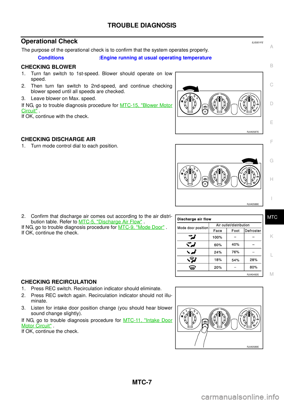
CHECKING BLOWER
1. Turn fan switch to 1st-speed. Blower should operate on low
speed.
2. Then turn fan switch to 2nd-speed, and continue checking
blower speed until all speeds are checked.
3. Leave blower on Max. speed.
If NG, go to trouble diagnosis procedure for MTC-15, "
Blower Motor
Circuit" .
If OK, continue with the check.
CHECKING DISCHARGE AIR
1. Turn mode control dial to each position.
2. Confirm that discharge air comes out according to the air distri-
bution table. Refer to MTC-5, "
Discharge Air Flow" .
If NG, go to trouble diagnosis procedure for MTC-9, "
Mode Door" .
If OK, continue the check.
CHECKING RECIRCULATION
1. Press REC switch. Recirculation indicator should eliminate.
2. Press REC switch again. Recirculation indicator should not illu-
minate.
3. Listen for intake door position change (you should hear blower
sound change slightly).
If NG, go to trouble diagnosis procedure for MTC-11, "
Intake Door
Motor Circuit" .
If OK, continue the check.Conditions :Engine running at usual operating temperature
RJIA0587E
RJIA0588E
RJIA0492E
RJIA0589E
Page 3628 of 4179
MTC-20
TROUBLE DIAGNOSIS
*1 QR engine; CO-9, "Changing Engine
Coolant" or YD engine; CO-31,
"Changing Engine Coolant" .*2 QR engine; CO-13, "
Checking Radi-
ator Cap" or YD engine; CO-35,
"Checking Radiator Cap" .*3 QR engine; (WITH EURO-OBD) EC-
162, "DTC P0117, P0118 ECT SEN-
SOR" .
QR engine; (WITHOUT EURO-OBD)
EC-597, "
DTC P0117, P0118 ECT
SENSOR" .
YD engine; (WITH EURO-OBD) EC-
981, "DTC P0117, P0118 ECT SEN-
SOR" .
YD engine; (WITHOUT EURO-OBD)
EC-1291, "
DTC P0117, P0118 ECT
SENSOR" .
*4 QR engine; CO-9, "
Changing Engine
Coolant" or YD engine; CO-31,
"Changing Engine Coolant" .*5 MTC-7, "
Operational Check" .*6MTC-3, "SYMPTOM TABLE".
Page 3635 of 4179
HEATER UNIT
MTC-27
C
D
E
F
G
H
I
K
L
MA
B
MTC
HEATER UNITPFP:27100
Removal and InstallationEJS001F9
REMOVAL
1. Drain coolant from cooling system. Refer to CO-9, "Changing Engine Coolant" for QR engine or CO-31,
"Changing Engine Coolant" for YD engine.
2. Disconnect two heater hoses from heater core pipe.
3. Remove instrument panel. Refer to IP-11, "
Removal and Installation" .
4. Remove blower unit. Refer to ATC-125, "
BLOWER UNIT" .
5. Remove clips of vehicle harness from steering member.
6. Remove mounting nuts, and then remove instrument stay.
7. Remove mounting bolts from heater (& cooling) unit.
RJIA0060E
RJIA0061E
RJIA2444E
Page 3636 of 4179
MTC-28
HEATER UNIT
8. Remove steering member.
NOTE:
This illustration is for RHD models. The layout for LHD models is symmetrically opposite.
9. Remove heater unit.
INSTALLATION
Installation is basically the reverse order of removal.
NOTE:
When filling radiator with coolant, refer to CO-9, "
Changing Engine Coolant" for QR engine or CO-31, "Chang-
ing Engine Coolant" for YD engine.
RJIA2404E
Page 3645 of 4179

SC-1
STARTING & CHARGING SYSTEM
K ELECTRICAL
CONTENTS
C
D
E
F
G
H
I
J
L
M
SECTION
A
B
SC
STARTING & CHARGING SYSTEM
PRECAUTIONS .......................................................... 2
Precautions for Supplemental Restraint System
(SRS) “AIR BAG” and “SEAT BELT PRE-TEN-
SIONER” .................................................................. 2
Wiring Diagrams and Trouble Diagnosis .................. 2
BATTERY .................................................................... 3
How to Handle Battery ............................................. 3
METHODS OF PREVENTING OVER-DIS-
CHARGE ............................................................... 3
CHECKING ELECTROLYTE LEVEL .................... 3
SPECIFIC GRAVITY CHECK ............................... 4
Battery Test and Charging Chart .............................. 5
CHART I ................................................................ 5
CHART II ............................................................... 6
A: SLOW CHARGE ............................................... 7
B: STANDARD CHARGE ...................................... 8
C: QUICK CHARGE ............................................ 10
Removal and Installation ......................................... 11
CHARGING SYSTEM ............................................... 12
System Description ................................................ 12
Wiring Diagram — CHARGE — /WITH GASOLINE
ENGINE ................................................................. 13
Wiring Diagram — CHARGE — /WITH DIESEL
ENGINE ................................................................. 14
Trouble Diagnoses ................................................. 15
WITH IC REGULATOR ....................................... 15
MALFUNCTION INDICATOR .............................. 15
Removal and Installation ........................................ 16
REMOVAL (QR ENGINE MODELS) ................... 16
REMOVAL (YD ENGINE MODELS) ................... 16
INSTALLATION ................................................... 16
Disassembly and Assembly ................................... 17
QR ENGINE MODELS ........................................ 17
YD ENGINE MODELS ........................................ 18
Disassembly ........................................................... 18
REAR COVER .................................................... 18REAR BEARING ................................................. 18
Inspection ............................................................... 19
ROTOR CHECK .................................................. 19
BRUSH CHECK .................................................. 19
PULLEY CHECK (WITH CLUTCH TYPE) ........... 19
STATOR CHECK ................................................. 19
Assembly ................................................................ 20
RING FITTING IN REAR BEARING .................... 20
REAR COVER INSTALLATION ........................... 20
STARTING SYSTEM ................................................. 21
System Description ................................................. 21
M/T MODELS ...................................................... 21
A/T MODELS ....................................................... 21
Wiring Diagram — START —/M/T models ............. 22
Wiring Diagram — START —/A/T models .............. 23
Trouble Diagnoses ................................................. 24
Removal and Installation ........................................ 25
REMOVAL ........................................................... 25
INSTALLATION ................................................... 25
Disassembly and Assembly .................................... 26
QR ENGINE MODELS ........................................ 26
YD ENGINE MODELS ........................................ 28
Inspection ............................................................... 29
MAGNETIC SWITCH CHECK ............................. 29
PINION/CLUTCH CHECK ................................... 29
BRUSH CHECK .................................................. 29
YOKE CHECK ..................................................... 30
ARMATURE CHECK ........................................... 31
Assembly ................................................................ 32
PINION PROTRUSION LENGTH ADJUST-
MENT .................................................................. 32
SERVICE DATA AND SPECIFICATIONS (SDS) ...... 34
Battery .................................................................... 34
Starter ..................................................................... 34
Alternator ................................................................ 34
Page 3647 of 4179

BATTERY
SC-3
C
D
E
F
G
H
I
J
L
MA
B
SC
BATTERY PFP:00011
How to Handle Battery EKS00313
CAUTION:
�If it becomes necessary to start the engine with a booster battery and jumper cables, use a 12-volt
booster battery.
�After connecting battery cables, ensure that they are tightly clamped to battery terminals for good
contact.
�Never add distilled water through the hole used to check specific gravity.
METHODS OF PREVENTING OVER-DISCHARGE
The following precautions must be taken to prevent over-discharging a battery.
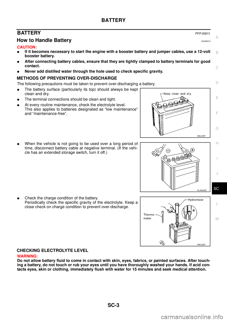
�The battery surface (particularly its top) should always be kept
clean and dry.
�The terminal connections should be clean and tight.
�At every routine maintenance, check the electrolyte level.
This also applies to batteries designated as “low maintenance”
and “maintenance-free”.
�When the vehicle is not going to be used over a long period of
time, disconnect battery cable at negative terminal. (If the vehi-
cle has an extended storage switch, turn it off.)
�Check the charge condition of the battery.
Periodically check the specific gravity of the electrolyte. Keep a
close check on charge condition to prevent over-discharge.
CHECKING ELECTROLYTE LEVEL
WARNING:
Do not allow battery fluid to come in contact with skin, eyes, fabrics, or painted surfaces. After touch-
ing a battery, do not touch or rub your eyes until you have thoroughly washed your hands. If acid con-
tacts eyes, skin or clothing, immediately flush with water for 15 minutes and seek medical attention.
MEL040F
ELA0349D
MEL042F
Page 3656 of 4179

SC-12
CHARGING SYSTEM
CHARGING SYSTEM PFP:00011
System Description EKS00316
The alternator provides DC voltage to operate the vehicle's electrical system and to keep the battery charged.
The voltage output is controlled by the IC regulator.
Power is supplied at all times
�through 10A fuse (No. 34, located in the fuse and fusible link box)
�to alternator terminal 4 (S).
Terminal B supplies power to charge the battery and operate the vehicle's electrical system. Output voltage is
controlled by the IC regulator at terminal 4 (S) detecting the input voltage. The charging circuit is protected by
the 120A (Gasoline engine models) or 100A (Diesel engine models) fusible link (letter A, located in the fuse
and fusible link box).
The alternator is grounded to the engine block.
With the ignition switch in the ON or START position, power is supplied
�through 10A fuse [No. 11, located in the fuse block (J/B)]
�to combination meter terminal 2 for the charge warning lamp.
Ground is supplied with power and ground supplied
�to terminal 5 of the combination meter
�through alternator terminal 3 (L)
�to alternator terminal E (Gasoline engine models) or through body ground (Diesel engine models)
�through body ground E30 (Gasoline engine models).
The charge warning lamp will illuminate. When the alternator is providing sufficient voltage with the engine
running, the ground is opened and the charge warning lamp will go off.
If the charge warning lamp illuminates with the engine running, a malfunction is indicated.
Page 3657 of 4179
CHARGING SYSTEM
SC-13
C
D
E
F
G
H
I
J
L
MA
B
SC
Wiring Diagram — CHARGE — /WITH GASOLINE ENGINEEKS00317
TKWA1513E