Page 3594 of 4179
MA-34
ENGINE MAINTENANCE (YD22DDTI)
�The oil filter is provided with a relief valve.
INSTALLATION
1. Remove foreign materials adhering to the oil filter installation surface.
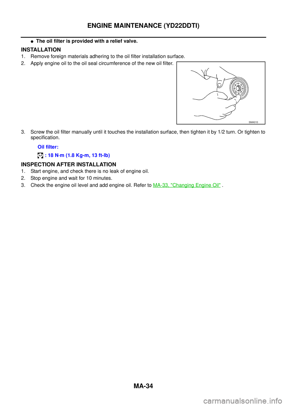
2. Apply engine oil to the oil seal circumference of the new oil filter.
3. Screw the oil filter manually until it touches the installation surface, then tighten it by 1/2 turn. Or tighten to
specification.
INSPECTION AFTER INSTALLATION
1. Start engine, and check there is no leak of engine oil.
2. Stop engine and wait for 10 minutes.
3. Check the engine oil level and add engine oil. Refer to MA-33, "
Changing Engine Oil" .
SMA010
Oil filter:
: 18 N·m (1.8 Kg-m, 13 ft-lb)
Page 3595 of 4179
ENGINE MAINTENANCE (YD22DDTI)
MA-35
C
D
E
F
G
H
I
J
K
MA
B
MA
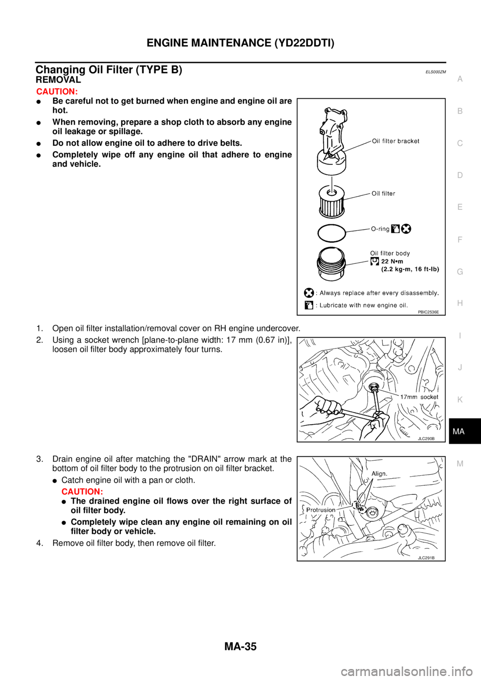
Changing Oil Filter (TYPE B)ELS000ZM
REMOVAL
CAUTION:
�Be careful not to get burned when engine and engine oil are
hot.
�When removing, prepare a shop cloth to absorb any engine
oil leakage or spillage.
�Do not allow engine oil to adhere to drive belts.
�Completely wipe off any engine oil that adhere to engine
and vehicle.
1. Open oil filter installation/removal cover on RH engine undercover.
2. Using a socket wrench [plane-to-plane width: 17 mm (0.67 in)],
loosen oil filter body approximately four turns.
3. Drain engine oil after matching the "DRAIN" arrow mark at the
bottom of oil filter body to the protrusion on oil filter bracket.
�Catch engine oil with a pan or cloth.
CAUTION:
�The drained engine oil flows over the right surface of
oil filter body.
�Completely wipe clean any engine oil remaining on oil
filter body or vehicle.
4. Remove oil filter body, then remove oil filter.
PBIC2536E
JLC290B
JLC291B
Page 3596 of 4179

5. Remove O-ring from oil filter body.
�Push O-ring in one direction, lift the slack part using fingers,
and remove O-ring from oil filter body.
CAUTION:
Do not u")
MA-36
ENGINE MAINTENANCE (YD22DDTI)
5. Remove O-ring from oil filter body.
�Push O-ring in one direction, lift the slack part using fingers,
and remove O-ring from oil filter body.
CAUTION:
Do not use a screwdrivers etc. as they may cause dam-
age to oil filter body.
INSTALLATION
1. Completely remove all foreign objects adhering to the inside of oil filter body or O-ring mounting area
(body side and bracket side).
2. Install oil filter and O-ring to oil filter body.
�Push oil filter into filter body completely.
3. Install oil filter body to oil filter bracket.
INSPECTION AFTER INSTALLATION
1. After warming up engine, check there is no leaks of engine oil.
2. Stop engine and wait for 10 minutes.
3. Check the engine oil level and add engine oil. Refer to MA-33, "
Changing Engine Oil" .
Draining WaterELS000CJ
1. Prepare a tray at the drain hose open end.
2. Loosen drain cock, and operate priming pump to drain water
from fuel filter.
CAUTION:
�Water in filter is drained with fuel. Prepare larger capacity
pan than fuel filter volume.
�Drained water is mixed with fuel. Prevent fuel from adher-
ing to rubber parts such as engine mount insulator.
3. After draining, close drain cock by hand.
CAUTION:
If drain cock is tightened excessively, it may be damaged
and fuel will leak. Do not use tools to tighten drain cock.
4. Bleed air in fuel piping. Refer to FL-18, "
Air Bleeding" .
5. Start engine and make sure there is no fuel leakage.
JLC292B
Oil filter body:
: 22 N·m (2.2 Kg-m, 16 ft-lb)
SBIA0138E
Page 3598 of 4179

MA-38
CHASSIS AND BODY MAINTENANCE
Changing M/T OilELS000BD
1. Drain oil from drain plug and refill with new gear oil.
2. Check oil level.
CAUTION:
Do not reuse gasket.
Checking A/T FluidELS000BV
1. Warm up engine.
2. Check for fluid leakage.
3. Before driving, fluid level can be checked at fluid temperatures of 30 to 50°C (86 to 122°F) using “COLD”
range on dipstick.
a. Park vehicle on level surface and set parking brake.
b. Start engine and move selector lever through each gear position. Leave selector lever in “P” position.
c. Check fluid level with engine idling.
d. Remove dipstick and wipe clean lint-free paper.
CAUTION:
When wiping away the dipstick, always use lint-free paper, not cloth one.
e. Re-insert dipstick into charging pipe as far as it will go.
CAUTION:
To check fluid level, insert the dipstick until the cap contacts the end of the A/T fluid charging pipe,
with the dipstick reversed from the normal attachment conditions.
f. Remove dipstick and note reading. If reading is at low side of range, add fluid to the A/T fluid charging
pipe.
CAUTION:
Do not overfill.
4. Drive vehicle for approximately 5 minutes in urban areas.
5. Re-check fluid level at fluid temperatures of 50 to 80°C (122 to 176°F) using “HOT” range on dipstick.
CAUTION:
�When wiping away the dipstick, always use lint-free paper, not cloth one.
�To check fluid level, insert the dipstick until the cap contacts the end of the A/T fluid charging
pipe, with the dipstick reversed from the normal attachment conditions.Oil grade:
API GL-4
Viscosity:
Refer to MA-17, "
RECOMMENDED FLUIDS AND
LUBRICANTS"
Oil capacity:
Approx. 2.3 (4 lmp pt)
Filler plug and drain plug:
: 30 - 39 N·m (3.1 - 3.9 kg-m, 23 - 28 ft-lb)
SCIA0361E
SMA146B
Page 3599 of 4179

CHASSIS AND BODY MAINTENANCE
MA-39
C
D
E
F
G
H
I
J
K
MA
B
MA
6. Check fluid condition.
�If fluid is very dark or smells burned, refer to AT section for
checking operation of A/T. Flush cooling system after repair of
A/T.
�If A/T fluid contains frictional material (clutches, bands, etc.),
replace radiator and flush cooler line using cleaning solvent
and compressed air after repair of A/T. Refer to CO-12,
"RADIATOR" , CO-14, "RADIATOR (ALUMINUM TYPE)" .
7. Install the removed dipstick in the A/T fluid charging pipe.
Changing A/T FluidELS000BW
1. Warm up A/T fluid.
2. Stop engine.
3. Drain A/T fluid from drain plug and refill with new A/T fluid.
Always refill same volume with drained fluid.
4. Run engine at idle speed for five minutes.
5. Check fluid level and condition. Refer to MA-38, "
Checking A/T Fluid" . If fluid is still dirty, repeat steps 2
through 5.
Checking Transfer OilELS000BT
Check for oil leakage and oil level.
CAUTION:
Never start engine while checking oil level.
Changing Transfer OilELS000BU
1. Drain oil from drain plug and refill with new gear oil.
SMA853B
Fluid grade:
Genuine Nissan ATF or equivalent. Refer to MA-
17, "RECOMMENDED FLUIDS AND LUBRI-
CANTS" .
Fluid capacity (With torque converter):
Approx. 8.5 (7-1/2 lmp qt)
Drain plug:
: 34 N·m (3.5 kg-m, 25 ft-lb)
SMA052D
Filler plug:
: 9.8 - 19.6 N·m (1.0 - 1.9 kg-m, 87 - 173 in-lb)
SDIA0513E
Page 3604 of 4179

MA-44
CHASSIS AND BODY MAINTENANCE
Checking Power Steering Fluid and LinesELS000BP
Check fluid level in reservoir tank with engine off.
Use “HOT” range at fluid temperatures of 50 to 80°C (122 to 176°F)
or “COLD” range at fluid temperatures of 0 to 30°C (32 to 86°F).
CAUTION:
�Do not overfill.
�Recommended fluid is DEXRONTM III type ATF or equiva-
lent.
Refer to MA-17, "
RECOMMENDED FLUIDS AND LUBRI-
CANTS"
�Check lines for improper attachment, leaks, cracks, dam-
age, loose connections, chafing and deterioration.
�Check rack boots for accumulation of power steering fluid.
Axle and Suspension PartsELS000BQ
Check front and rear axle and suspension parts for excessive play,
cracks, wear or other damage.
�Shake each wheel to check for excessive play.
�Check wheel bearings for smooth operation.
�Check axle and suspension nuts and bolts for looseness.
�Check strut (shock absorber) for oil leakage or other damage.
�Check suspension ball joint for grease leakage and ball joint
dust cover for cracks or other damage.
SST850C
SST851C
SMA525A
SFA392B
Page 3605 of 4179
CHASSIS AND BODY MAINTENANCE
MA-45
C
D
E
F
G
H
I
J
K
MA
B
MA
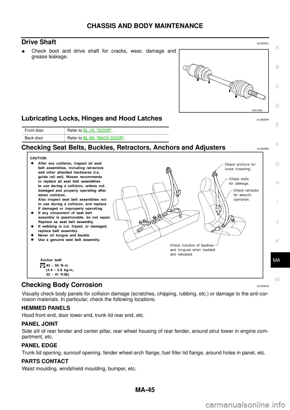
Drive ShaftELS000CL
�Check boot and drive shaft for cracks, wear, damage and
grease leakage.
Lubricating Locks, Hinges and Hood LatchesELS000BR
Checking Seat Belts, Buckles, Retractors, Anchors and AdjustersELS000BS
Checking Body CorrosionELS000C0
Visually check body panels for collision damage (scratches, chipping, rubbing, etc.) or damage to the anti-cor-
rosion materials. In particular, check the following locations.
HEMMED PANELS
Hood front end, door lower end, trunk lid rear end, etc.
PA N E L J O I N T
Side sill of rear fender and center pillar, rear wheel housing of rear fender, around strut tower in engine com-
partment, etc.
PA N E L E D G E
Trunk lid opening, sunroof opening, fender wheel-arch flange, fuel filler lid flange, around holes in panel, etc.
PARTS CONTACT
Waist moulding, windshield moulding, bumper, etc.
SFA108A
Front door Refer to BL-18, "DOOR" .
Back door Refer to BL-99, "
BACK DOOR" .
Page 3607 of 4179

MA-47
C
D
E
F
G
H
I
J
K
MA
B
MA
SERVICE DATA AND SPECIFICATIONS (SDS)PFP:00030
Standard and LimitELS000K3
BELT DEFLECTION AND TENSION
QR20DE and QR25DE
YD22DDTi")
SERVICE DATA AND SPECIFICATIONS (SDS)
MA-47
C
D
E
F
G
H
I
J
K
MA
B
MA
SERVICE DATA AND SPECIFICATIONS (SDS)PFP:00030
Standard and LimitELS000K3
BELT DEFLECTION AND TENSION
QR20DE and QR25DE
YD22DDTi
*: When engine is cold.
RADIATOR
Unit: kPa (bar, kg/cm2 , psi)
ENGINE COOLANT CAPACITY
QR20DE and QR25DE
Unit: (lmp qt)
YD22DDTi
Unit: (lmp qt)
ENGINE OIL CAPACITY (APPROXIMATE)
QR20DE and QR25DE
Unit: (lmp qt)
YD22DDTi
Unit: (lmp qt)
SPARK PLUG
QR20DE and QR25DE
Tensions of drive belts Auto-adjustment by auto-tensioner
Applied beltBelt deflection with 98 N (10 kg, 22 lb) force applied* mm (in)
New Adjusted Limit for re-adjusting
A/C compressor belt 4 - 5 (0.16 - 0.20) 6 - 7 (0.24 - 0.28) 8.5 (0.335)
Alternator and water pump belt 9.0 - 10.5 (0.354 - 0.413) 11.0 - 12.5 (0.433 - 0.492) 16.5 (0.650)
Cap relief pressureStandard 78 - 98 (0.78 - 0.98, 0.8 - 1.0, 11 - 14)
Limit 59 (0.59, 0.6, 9)
Leakage test pressure 157 (1.57, 1.6, 23)
Coolant capacity (With reservoir tank at “MAX” level) 7.1 (6-1/4)
Reservoir tank coolant capacity (At “MAX” level) 0.6 (1/2)
Coolant capacity (With reservoir tank at “MAX” level) 9.5 (8-3/8)
Reservoir tank coolant capacity (At “MAX” level) 0.6 (1/2)
Drain and refill With oil filter change 3.9 (3-3/8)
Without oil filter change 3.5 (3-1/8)
Dry engine (Overhaul)4.5 (4)
Drain and refill With oil filter change 5.2 (4-5/8)
Without oil filter change 4.9 (4-3/8)
Dry engine (Overhaul)6.3 (5-1/2)
MakeNGK
Standard typeLFR5A-11
Hot typeLFR4A-11
Cold typeLFR6A-11
Spark plug gap mm (in) 1.0 - 1.1 (0.039 - 0.043)