Page 1 of 4179

MODEL T30 SERIES
2004NISSANEUROPES.A.S.
All rights reserved. No part of this Electronic Service Manual may be reproduced or stored in a retrieval system, or transmitted in any
form, or by any means, electronic, mechanical, photocopying, recording or otherwise, without the prior written permission of Nissan
Europe S.A.S., Paris, France.
A GENERAL INFORMATION
B ENGINE
C TRANSMISSION/TRANSAXLE
D DRIVELINE/AXLE
E SUSPENSION F BRAKES
G STEERING H RESTRAINTS
I BODY
J AIR CONDITIONER
K ELECTRICAL
L MAINTENANCE
M INDEXGI General Information
EM Engine Mechanical
LU Engine Lubrication System
CO Engine Cooling System
EC Engine Control System
FL Fuel System
EX Exhaust System
ACC Accelerator Control System
CL Clutch
MT Manual Transaxle
AT Automatic Transaxle
TF Transfer
PR Propeller Shaft
RFD Rear Final Drive
FAX Front Axle
RAX Rear Axle
FSU Front Suspension
RSU Rear Suspension
WT Road Wheels & Tires
BR Brake System
PB Parking Brake System
BRC Brake Control System
PS Power Steering System
SB Seat Belts
SRS Supplemental Restraint System (SRS)
BL Body, Lock & Security System
GW Glasses, Window System & Mirrors
RF Roof
EI Exterior & Interior
IP Instrument Panel
SE Seat
ATC Automatic Air Conditioner
MTC Manual AIr Conditioner
SC Starting & Charging System
LT Lighting System
DI Driver Information System
WW Wiper, Washer & Horn
BCS Body Control System
LAN LAN System
AV Audio Visual, Navigation & Telephone System
PG Power Supply, Ground & Circuit Elements
MA Maintenance
IDX Alphabetical Index
QUICK REFERENCE INDEX
A
B
C
D
E
F
G
H
I
J
K
L
M
Page 71 of 4179
![NISSAN X-TRAIL 2003 Service Repair Manual INTAKE MANIFOLD
EM-19
[QR]
C
D
E
F
G
H
I
J
K
L
MA
EM
Electric Throttle Control Actuator
�Tighten mounting bolts equally and diagonally in several steps
and in numerical order as shown in the figure.](/manual-img/5/57404/w960_57404-70.png "NISSAN X-TRAIL 2003 Service Repair Manual INTAKE MANIFOLD
EM-19
[QR]
C
D
E
F
G
H
I
J
K
L
MA
EM
Electric Throttle Control Actuator
�Tighten mounting bolts equally and diagonally in several steps
and in numerical order as shown in the figure.")
INTAKE MANIFOLD
EM-19
[QR]
C
D
E
F
G
H
I
J
K
L
MA
EM
Electric Throttle Control Actuator
�Tighten mounting bolts equally and diagonally in several steps
and in numerical order as shown in the figure.
�Perform the “Throttle Valve Closed Position Learning” when har-
ness connector of electric throttle control actuator is discon-
nected. Refer to EC-46, "
Throttle Valve Closed Position
Learning" (WITH EURO-OBD) or EC-508, "Throttle Valve
Closed Position Learning" (WITHOUT EURO-OBD).
�Perform the “Idle Air Volume Learning” and “Throttle Valve
Closed Position Learning” when electric throttle control actuator
is replaced. Refer to EC-46, "
Idle Air Volume Learning" (WITH
EURO-OBD) or EC-508, "
Idle Air Volume Learning" (WITHOUT
EURO-OBD).
INSPECTION AFTER INSTALLATION
Make sure there are no fuel leaks at connections with the following procedure:
1. Apply fuel pressure to fuel lines with turning ignition switch “ON” (with engine stopped). Then make sure
there are no fuel leaks at connections.
NOTE:
Use mirrors for checking on invisible points.
2. Start engine. With engine speed increased, make sure again there are no fuel leaks at connections.
CAUTION:
Do not touch engine immediately after stopped as engine becomes extremely hot.
EMJ1612D
Page 74 of 4179
![NISSAN X-TRAIL 2003 Service Repair Manual EM-22
[QR]
INTAKE MANIFOLD
INSTALLATION
Note the following, and install in the reverse order of removal.
Intake Manifold
�If stud bolts were removed, install them and tighten to the specified torque](/manual-img/5/57404/w960_57404-73.png "NISSAN X-TRAIL 2003 Service Repair Manual EM-22
[QR]
INTAKE MANIFOLD
INSTALLATION
Note the following, and install in the reverse order of removal.
Intake Manifold
�If stud bolts were removed, install them and tighten to the specified torque")
EM-22
[QR]
INTAKE MANIFOLD
INSTALLATION
Note the following, and install in the reverse order of removal.
Intake Manifold
�If stud bolts were removed, install them and tighten to the specified torque below.
�Tighten in numerical order as shown in the figure.
NOTE:
No. 6 means double tightening of bolt No. 1.
Intake Manifold Collector
Tighten in numerical order as shown in the figure.
NOTE:
No. 8 means double tightening of bolt No. 1.
Electric Throttle Control Actuator
�Tighten mounting bolts equally and diagonally in several steps
and in numerical order as shown in the figure.
�Perform the “Throttle Valve Closed Position Learning” when har-
ness connector of electric throttle control actuator is discon-
nected. Refer to EC-46, "
Throttle Valve Closed Position
Learning" (WITH EURO-OBD) or EC-508, "Throttle Valve
Closed Position Learning" (WITHOUT EURO-OBD).
�Perform the “Idle Air Volume Learning” and “Throttle Valve
Closed Position Learning” when electric throttle control actuator
is replaced. Refer to EC-46, "
Idle Air Volume Learning" (WITH
EURO-OBD) or EC-508, "
Idle Air Volume Learning" (WITHOUT
EURO-OBD).
INSPECTION AFTER INSTALLATION
Make sure there are no fuel leaks at connections with the following procedure:
1. Apply fuel pressure to fuel lines with turning ignition switch “ON” (with engine stopped). Then make sure
there are no fuel leaks at connections.
NOTE:
Use mirrors for checking on invisible points.
2. Start engine. With engine speed increased, make sure again there are no fuel leaks at connections.
CAUTION:
Do not touch engine immediately after stopped as engine becomes extremely hot. : 10.8 N·m (1.1 kg-m, 8 ft-lb)
SBIA0231E
SBIA0230E
EMJ1612D
Page 88 of 4179
![NISSAN X-TRAIL 2003 Service Repair Manual EM-36
[QR]
FUEL INJECTOR AND FUEL TUBE
�Insert until you hear a “click” sound and actually feel the engagement.
�To avoid misidentification of engagement with a similar sound, be sure to perform](/manual-img/5/57404/w960_57404-87.png "NISSAN X-TRAIL 2003 Service Repair Manual EM-36
[QR]
FUEL INJECTOR AND FUEL TUBE
�Insert until you hear a “click” sound and actually feel the engagement.
�To avoid misidentification of engagement with a similar sound, be sure to perform")
EM-36
[QR]
FUEL INJECTOR AND FUEL TUBE
�Insert until you hear a “click” sound and actually feel the engagement.
�To avoid misidentification of engagement with a similar sound, be sure to perform the next
step.
c. Before clamping fuel feed hose with hose clamps, pull quick connector hard by hand holding “A” position.
Make sure it is completely engaged (connected) so that it does not come out from fuel tube.
d. Install quick connector cap to quick connector connection. (On
both the engine side and the vehicle side)
�Install so that the arrow mark on the side faces up.
CAUTION:
�Make sure that quick connector and fuel tube are
securely fit into quick connector cap installation groove.
�If quick connector cap cannot be installed smoothly,
quick connector may have not been installed correctly.
Check connection again.
NOTE:
There is quick connector cap for the engine side and for the
vehicle side, and they have different shapes. The figure shows engine side as an example.
8. Install fuel feed hose to hose clamp.
9. Install in the reverse order of removal after this step.
INSPECTION AFTER INSTALLATION
Check on Fuel Leaks
1. Apply fuel pressure to fuel lines with turning ignition switch “ON” (with engine stopped). Then make sure
there are no fuel leaks at connections.
NOTE:
Use mirrors for checking on invisible points.
2. Start engine. With engine speed increased, make sure again there are no fuel leaks at connections.
CAUTION:
Do not touch engine immediately after stopped as engine becomes extremely hot.
PBIC2348E
Page 93 of 4179
![NISSAN X-TRAIL 2003 Service Repair Manual FUEL INJECTOR AND FUEL TUBE
EM-41
[QR]
C
D
E
F
G
H
I
J
K
L
MA
EM
�To avoid misidentification of engagement with a similar sound, be sure to perform the next
step.
c. Before clamping fuel feed hose w](/manual-img/5/57404/w960_57404-92.png "NISSAN X-TRAIL 2003 Service Repair Manual FUEL INJECTOR AND FUEL TUBE
EM-41
[QR]
C
D
E
F
G
H
I
J
K
L
MA
EM
�To avoid misidentification of engagement with a similar sound, be sure to perform the next
step.
c. Before clamping fuel feed hose w")
FUEL INJECTOR AND FUEL TUBE
EM-41
[QR]
C
D
E
F
G
H
I
J
K
L
MA
EM
�To avoid misidentification of engagement with a similar sound, be sure to perform the next
step.
c. Before clamping fuel feed hose with hose clamps, pull quick connector hard by hand holding “A” position.
Make sure it is completely engaged (connected) so that it does not come out from fuel feed tube.
d. Install quick connector cap to quick connector connection. (On
both the engine side and the vehicle side)
�Install so that the arrow mark on the side faces up.
CAUTION:
�Make sure that quick connector and fuel tube are
securely fit into quick connector cap installation groove.
�If quick connector cap cannot be installed smoothly,
quick connector may have not been installed correctly.
Check connection again.
NOTE:
There is quick connector cap for the engine side and for the
vehicle side, and they have different shapes. The figure shows engine side as an example.
7. Install fuel feed hose to hose clamp.
8. Install in the reverse order of removal after this step.
INSPECTION AFTER INSTALLATION
Check on Fuel Leaks
1. Apply fuel pressure to fuel lines with turning ignition switch “ON” (with engine stopped). Then make sure
there are no fuel leaks at connections.
NOTE:
Use mirrors for checking on invisible points.
2. Start engine. With engine speed increased, make sure again there are no fuel leaks at connections.
CAUTION:
Do not touch engine immediately after stopped as engine becomes extremely hot.
PBIC2348E
Page 190 of 4179
EM-138
[YD22DDTi]
INTAKE MANIFOLD
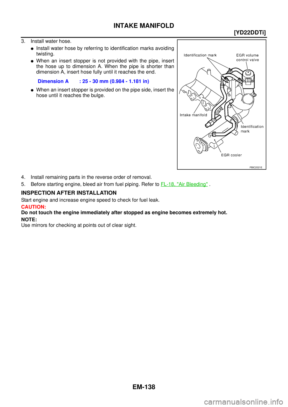
3. Install water hose.
�Install water hose by referring to identification marks avoiding
twisting.
�When an insert stopper is not provided with the pipe, insert
the hose up to dimension A. When the pipe is shorter than
dimension A, insert hose fully until it reaches the end.
�When an insert stopper is provided on the pipe side, insert the
hose until it reaches the bulge.
4. Install remaining parts in the reverse order of removal.
5. Before starting engine, bleed air from fuel piping. Refer to FL-18, "
Air Bleeding" .
INSPECTION AFTER INSTALLATION
Start engine and increase engine speed to check for fuel leak.
CAUTION:
Do not touch the engine immediately after stopped as engine becomes extremely hot.
NOTE:
Use mirrors for checking at points out of clear sight.Dimension A : 25 - 30 mm (0.984 - 1.181 in)
PBIC2021E
Page 212 of 4179
EM-160
[YD22DDTi]
INJECTION TUBE AND FUEL INJECTOR
CAUTION:
�Check gutter spring in nozzle oil seal on fuel injector for missing.
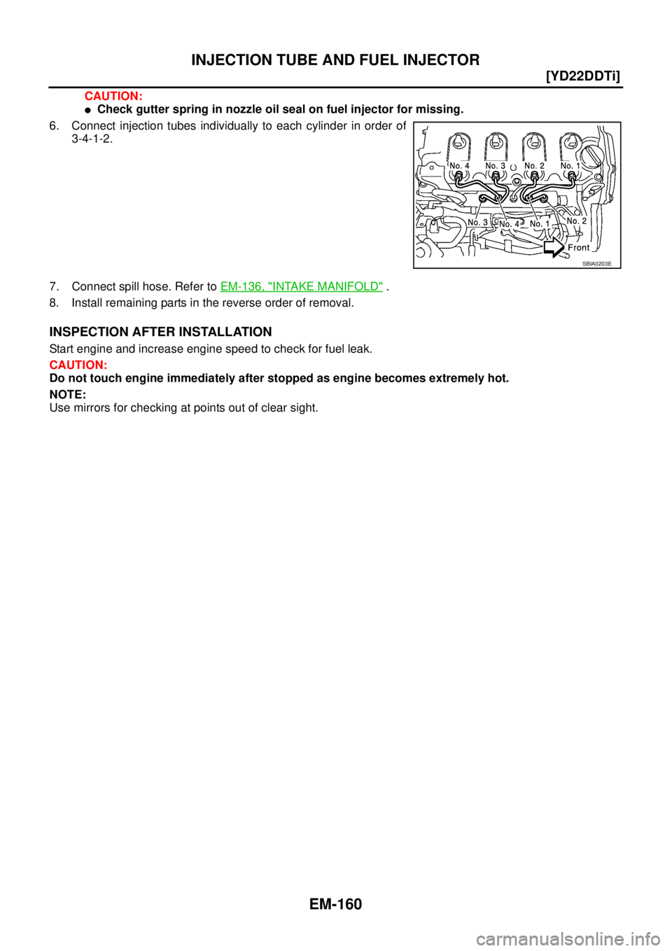
6. Connect injection tubes individually to each cylinder in order of
3-4-1-2.
7. Connect spill hose. Refer to EM-136, "
INTAKE MANIFOLD" .
8. Install remaining parts in the reverse order of removal.
INSPECTION AFTER INSTALLATION
Start engine and increase engine speed to check for fuel leak.
CAUTION:
Do not touch engine immediately after stopped as engine becomes extremely hot.
NOTE:
Use mirrors for checking at points out of clear sight.
SBIA0203E
Page 221 of 4179
ROCKER COVER
EM-169
[YD22DDTi]
C
D
E
F
G
H
I
J
K
L
MA
EM
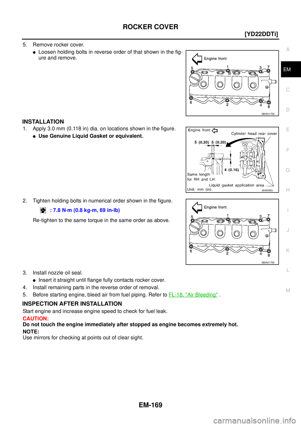
5. Remove rocker cover.
�Loosen holding bolts in reverse order of that shown in the fig-
ure and remove.
INSTALLATION
1. Apply 3.0 mm (0.118 in) dia. on locations shown in the figure.
�Use Genuine Liquid Gasket or equivalent.
2. Tighten holding bolts in numerical order shown in the figure.
Re-tighten to the same torque in the same order as above.
3. Install nozzle oil seal.
�Insert it straight until flange fully contacts rocker cover.
4. Install remaining parts in the reverse order of removal.
5. Before starting engine, bleed air from fuel piping. Refer to FL-18, "
Air Bleeding" .
INSPECTION AFTER INSTALLATION
Start engine and increase engine speed to check for fuel leak.
CAUTION:
Do not touch the engine immediately after stopped as engine becomes extremely hot.
NOTE:
Use mirrors for checking at points out of clear sight.
SBIA0175E
JEM248G
: 7.8 N·m (0.8 kg-m, 69 in-lb)
SBIA0175E