Page 3209 of 4179
REAR WINDOW DEFOGGER
GW-23
C
D
E
F
G
H
J
K
L
MA
B
GW
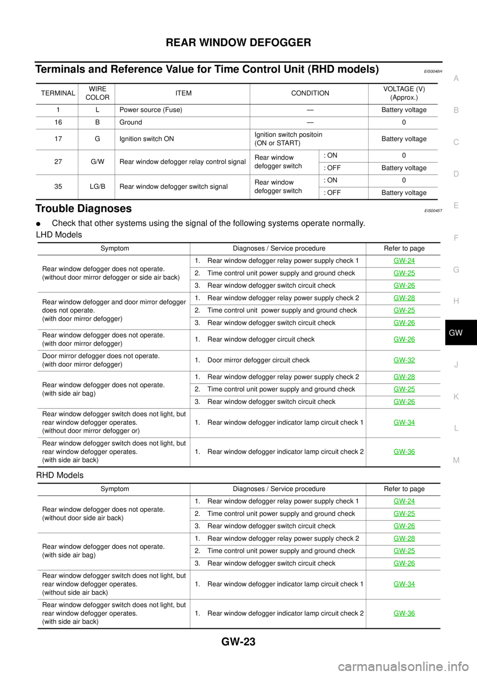
Terminals and Reference Value for Time Control Unit (RHD models)EIS0046H
Trouble DiagnosesEIS0045T
�Check that other systems using the signal of the following systems operate normally.
LHD Models
RHD Models
TERMINALWIRE
COLORITEM CONDITIONVOLTAGE (V)
(Approx.)
1 L Power source (Fuse) — Battery voltage
16 B Ground — 0
17 G Ignition switch ONIgnition switch positoin
(ON or START)Battery voltage
27 G/W Rear window defogger relay control signalRear window
defogger switch : ON 0
: OFF Battery voltage
35 LG/B Rear window defogger switch signalRear window
defogger switch: ON 0
: OFF Battery voltage
Symptom Diagnoses / Service procedure Refer to page
Rear window defogger does not operate.
(without door mirror defogger or side air back)1. Rear window defogger relay power supply check 1GW-24
2. Time control unit power supply and ground checkGW-25
3. Rear window defogger switch circuit checkGW-26
Rear window defogger and door mirror defogger
does not operate.
(with door mirror defogger)1. Rear window defogger relay power supply check 2GW-28
2. Time control unit power supply and ground checkGW-25
3. Rear window defogger switch circuit checkGW-26
Rear window defogger does not operate.
(with door mirror defogger)1. Rear window defogger circuit checkGW-26
Door mirror defogger does not operate.
(with door mirror defogger)1. Door mirror defogger circuit checkGW-32
Rear window defogger does not operate.
(with side air bag)1. Rear window defogger relay power supply check 2GW-282. Time control unit power supply and ground checkGW-25
3. Rear window defogger switch circuit checkGW-26
Rear window defogger switch does not light, but
rear window defogger operates.
(without door mirror defogger or)1. Rear window defogger indicator lamp circuit check 1GW-34
Rear window defogger switch does not light, but
rear window defogger operates.
(with side air back)1. Rear window defogger indicator lamp circuit check 2GW-36
Symptom Diagnoses / Service procedure Refer to page
Rear window defogger does not operate.
(without door side air back)1. Rear window defogger relay power supply check 1GW-24
2. Time control unit power supply and ground checkGW-25
3. Rear window defogger switch circuit checkGW-26
Rear window defogger does not operate.
(with side air bag)1. Rear window defogger relay power supply check 2GW-282. Time control unit power supply and ground checkGW-25
3. Rear window defogger switch circuit checkGW-26
Rear window defogger switch does not light, but
rear window defogger operates.
(without side air back)1. Rear window defogger indicator lamp circuit check 1GW-34
Rear window defogger switch does not light, but
rear window defogger operates.
(with side air back)1. Rear window defogger indicator lamp circuit check 2GW-36
Page 3218 of 4179

GW-32
REAR WINDOW DEFOGGER
Door Mirror Defogger Circuit CheckEIS008AQ
1. CHECK FUSE
Check 10A fuse [No.27, located in fuse block (J/B)]
NOTE:
Refer to GW-17, "
Component Parts and Harness Connector Location"
OK or NG
OK >> GO TO 2.
NG >> If fuse is blown, be sure to eliminate cause of malfunction before installing new fuse. Refer to PG-
2, "POWER SUPPLY ROUTING"
2. CHECK REAR WINDOW DEFOGGER RELAY POWER SUPPLY CIRCUIT
1. Turn ignition switch OFF.
2. Remove rear window defogger relay.
3. Turn ignition switch ON.
4. Check voltage between rear window defogger relay harness
connector B6 terminal 6 and ground.
OK or NG
OK >> GO TO 3.
NG >> Repair or replace harness between fuse block (J/B) and
rear window defogger relay.
3. CHECK REAR WINDOW DEFOGGER RELAY
Check continuity between rear window defogger relay terminal 6 and 7.
OK or NG
OK >> GO TO 4.
NG >> Replace rear window defogger relay.6 (R/B) - Ground : Battery voltage
PIIA9561E
Terminal Condition Continuity
6712V direct current supply
between terminals 1 and 2Ye s
No current supply No
SEC202B
Page 3219 of 4179
REAR WINDOW DEFOGGER
GW-33
C
D
E
F
G
H
J
K
L
MA
B
GW
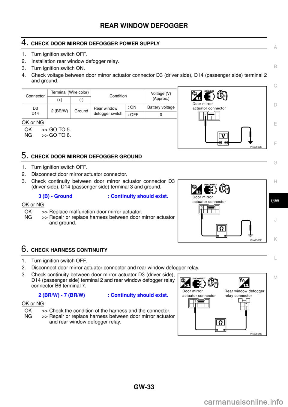
4. CHECK DOOR MIRROR DEFOGGER POWER SUPPLY
1. Turn ignition switch OFF.
2. Installation rear window defogger relay.
3. Turn ignition switch ON.
4. Check voltage between door mirror actuator connector D3 (driver side), D14 (passenger side) terminal 2
and ground.
OK or NG
OK >> GO TO 5.
NG >> GO TO 6.
5. CHECK DOOR MIRROR DEFOGGER GROUND
1. Turn ignition switch OFF.
2. Disconnect door mirror actuator connector.
3. Check continuity between door mirror actuator connector D3
(driver side), D14 (passenger side) terminal 3 and ground.
OK or NG
OK >> Replace malfunction door mirror actuator.
NG >> Repair or replace harness between door mirror actuator
and ground.
6. CHECK HARNESS CONTINUITY
1. Turn ignition switch OFF.
2. Disconnect door mirror actuator connector and rear window defogger relay.
3. Check continuity between door mirror actuator D3 (driver side),
D14 (passenger side) terminal 2 and rear window defogger relay
connector B6 terminal 7.
OK or NG
OK >> Check the condition of the harness and the connector.
NG >> Repair or replace harness between door mirror actuator
and rear window defogger relay.
ConnectorTerminal (Wire color)
ConditionVoltage (V)
(Approx.)
(+) (-)
D3
D142 (BR/W) GroundRear window
defogger switch: ON Battery voltage
: OFF 0
PIIA9562E
3 (B) - Ground : Continuity should exist.
PIIA9563E
2 (BR/W) - 7 (BR/W) : Continuity should exist.
PIIA9564E
Page 3272 of 4179
GW-86
DOOR MIRROR
DOOR MIRRORPFP:96301
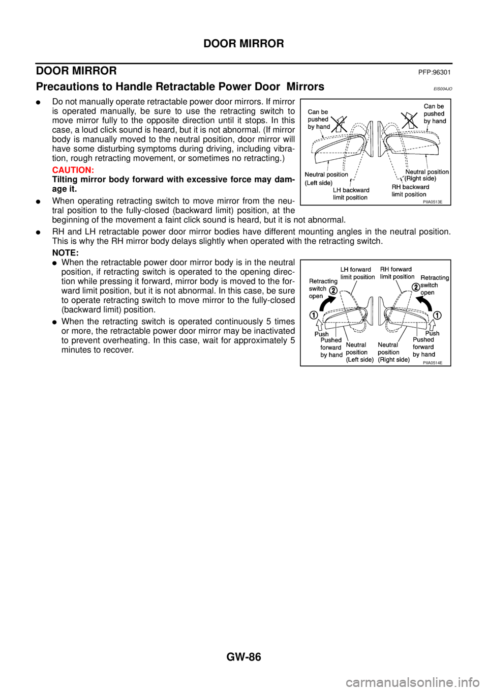
Precautions to Handle Retractable Power Door MirrorsEIS004JO
�Do not manually operate retractable power door mirrors. If mirror
is operated manually, be sure to use the retracting switch to
move mirror fully to the opposite direction until it stops. In this
case, a loud click sound is heard, but it is not abnormal. (If mirror
body is manually moved to the neutral position, door mirror will
have some disturbing symptoms during driving, including vibra-
tion, rough retracting movement, or sometimes no retracting.)
CAUTION:
Tilting mirror body forward with excessive force may dam-
age it.
�When operating retracting switch to move mirror from the neu-
tral position to the fully-closed (backward limit) position, at the
beginning of the movement a faint click sound is heard, but it is not abnormal.
�RH and LH retractable power door mirror bodies have different mounting angles in the neutral position.
This is why the RH mirror body delays slightly when operated with the retracting switch.
NOTE:
�When the retractable power door mirror body is in the neutral
position, if retracting switch is operated to the opening direc-
tion while pressing it forward, mirror body is moved to the for-
ward limit position, but it is not abnormal. In this case, be sure
to operate retracting switch to move mirror to the fully-closed
(backward limit) position.
�When the retracting switch is operated continuously 5 times
or more, the retractable power door mirror may be inactivated
to prevent overheating. In this case, wait for approximately 5
minutes to recover.
PIIA0513E
PIIA0514E
Page 3273 of 4179
DOOR MIRROR
GW-87
C
D
E
F
G
H
J
K
L
MA
B
GW
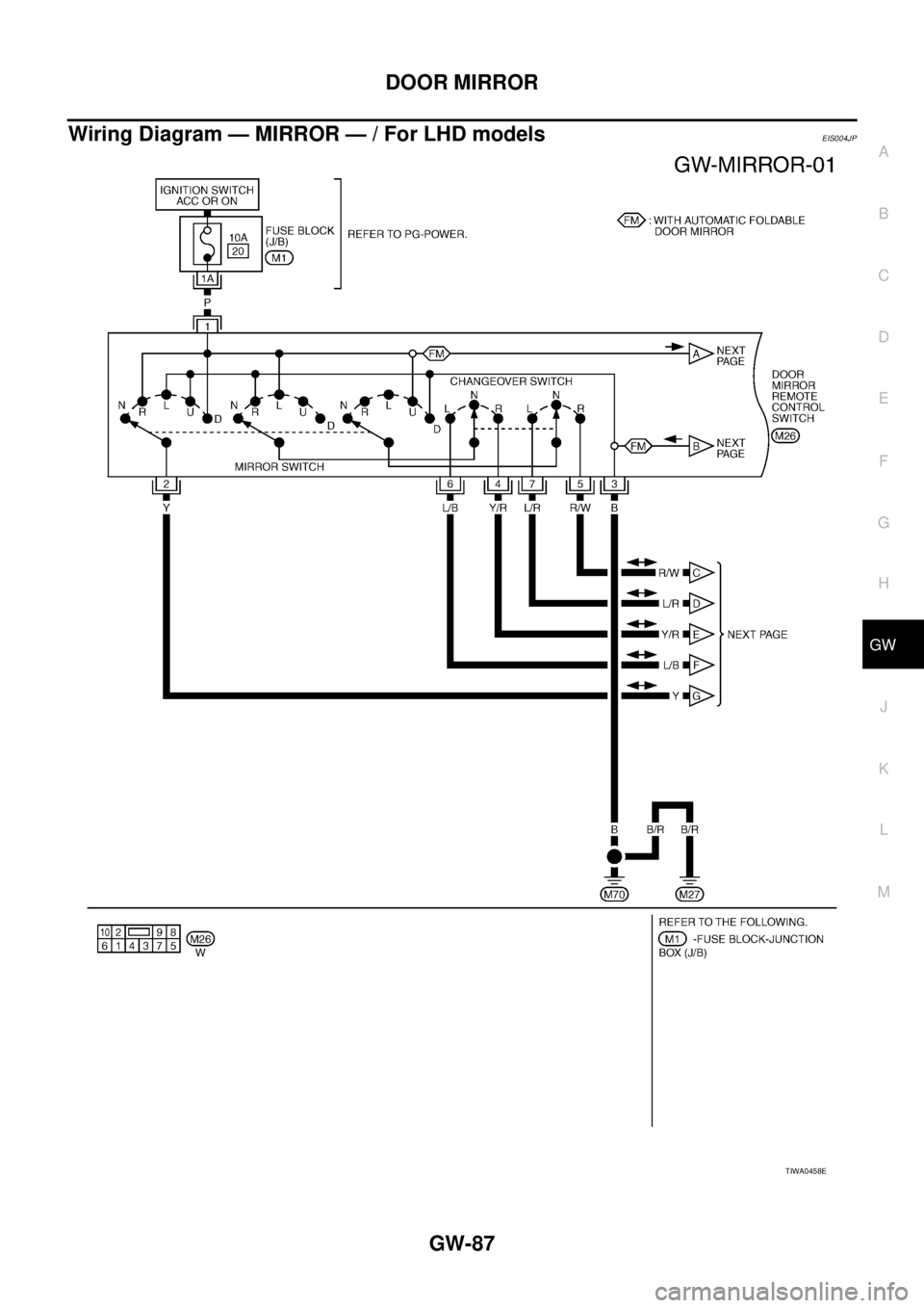
Wiring Diagram — MIRROR — / For LHD modelsEIS004JP
TIWA0458E
Page 3274 of 4179
GW-88
DOOR MIRROR
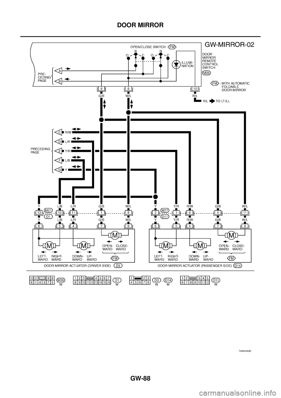
TIWA0459E
Page 3275 of 4179
DOOR MIRROR
GW-89
C
D
E
F
G
H
J
K
L
MA
B
GW
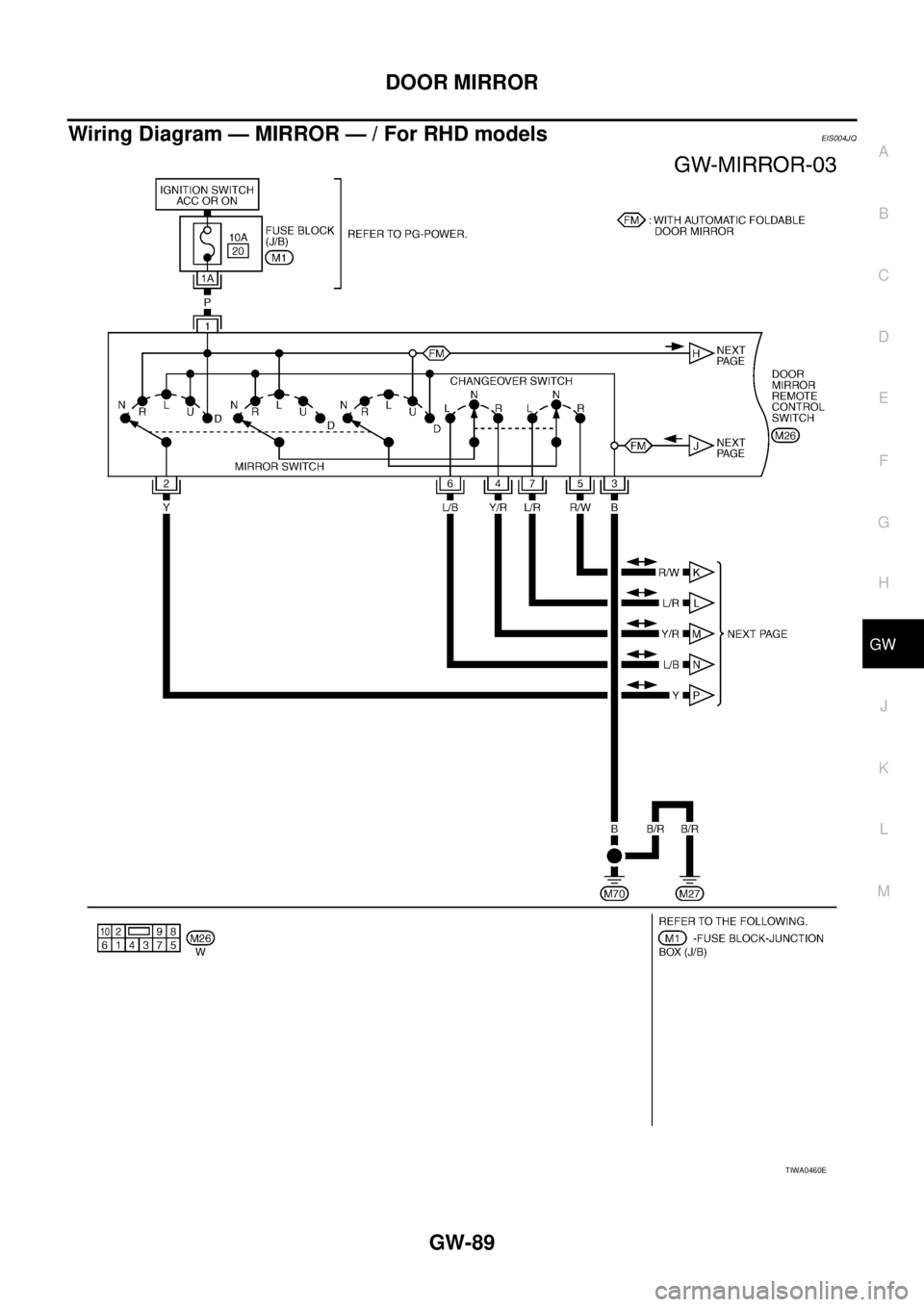
Wiring Diagram — MIRROR — / For RHD modelsEIS004JQ
TIWA0460E
Page 3276 of 4179
GW-90
DOOR MIRROR
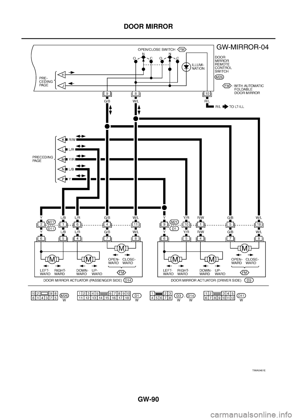
TIWA0461E