Page 3277 of 4179
DOOR MIRROR
GW-91
C
D
E
F
G
H
J
K
L
MA
B
GW
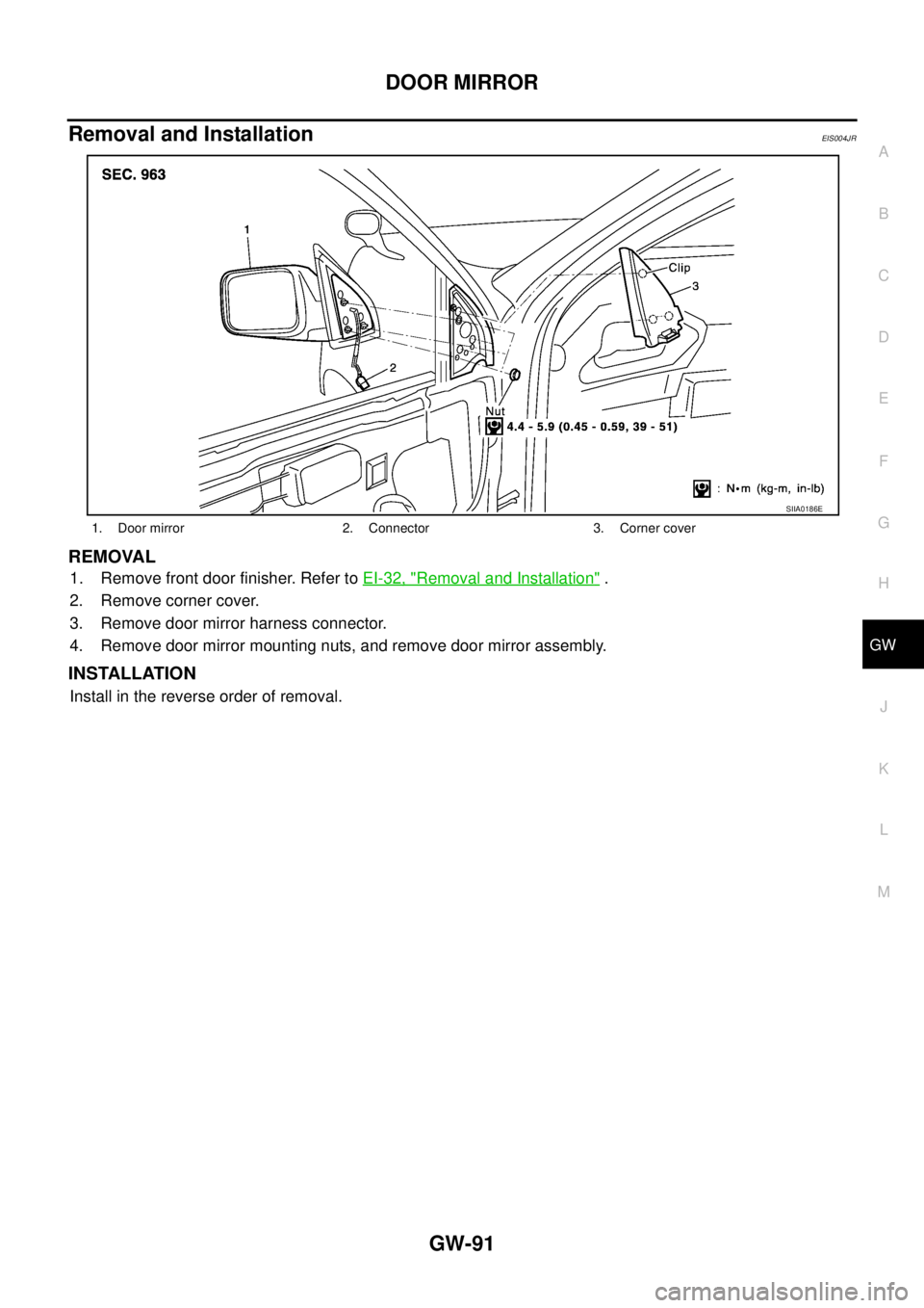
Removal and InstallationEIS004JR
REMOVAL
1. Remove front door finisher. Refer to EI-32, "Removal and Installation" .
2. Remove corner cover.
3. Remove door mirror harness connector.
4. Remove door mirror mounting nuts, and remove door mirror assembly.
INSTALLATION
Install in the reverse order of removal.
1. Door mirror 2. Connector 3. Corner cover
SIIA0186E
Page 3278 of 4179
GW-92
DOOR MIRROR
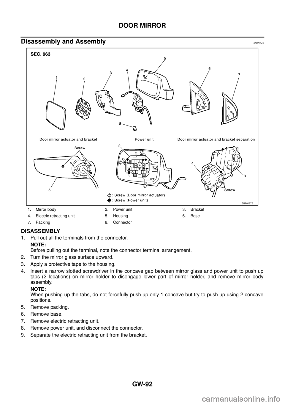
Disassembly and AssemblyEIS004JS
DISASSEMBLY
1. Pull out all the terminals from the connector.
NOTE:
Before pulling out the terminal, note the connector terminal arrangement.
2. Turn the mirror glass surface upward.
3. Apply a protective tape to the housing.
4. Insert a narrow slotted screwdriver in the concave gap between mirror glass and power unit to push up
tabs (2 locations) on mirror holder to disengage lower part of mirror holder, and remove mirror body
assembly.
NOTE:
When pushing up the tabs, do not forcefully push up only 1 concave but try to push up using 2 concave
positions.
5. Remove packing.
6. Remove base.
7. Remove electric retracting unit.
8. Remove power unit, and disconnect the connector.
9. Separate the electric retracting unit from the bracket.
1. Mirror body 2. Power unit 3. Bracket
4. Electric retracting unit 5. Housing 6. Base
7. Packing 8. Connector
SIIA0187E
Page 3279 of 4179
DOOR MIRROR
GW-93
C
D
E
F
G
H
J
K
L
MA
B
GW
ASSEMBLY
1. Install bracket to the electric retracting unit.
2. Connect power unit connector. Install electric retracting unit (bracket).
3. Install electric retracting unit and base to the housing.
4. Place power unit and mirror body assembly in a horizontal position.
5. Engage upper tabs of mirror glass with power unit. Then, press lower part of mirror glass down until the
lower part snaps to allow engagement of lower tabs.
NOTE:
After installation, visually check that the lower tabs (2) are securely engaged when viewed from the bot-
tom of mirror surface.
6. Install the packing to the base.
7. Insert the harness terminal into the connector.
NOTE:
Make sure to insert the harness terminal into the correct connector. Do not confuse the locations.
Page 3280 of 4179
GW-94
INSIDE MIRROR
INSIDE MIRRORPFP:96321
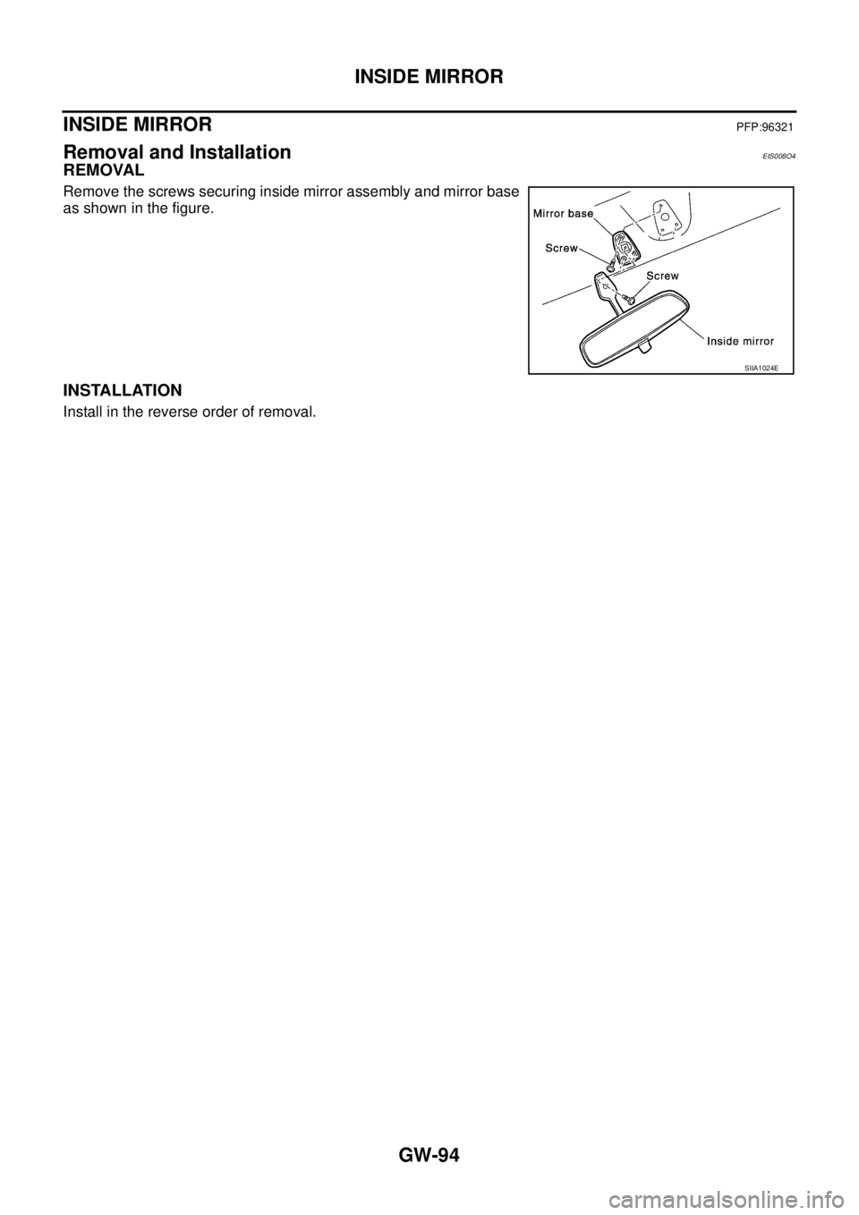
Removal and InstallationEIS008O4
REMOVAL
Remove the screws securing inside mirror assembly and mirror base
as shown in the figure.
INSTALLATION
Install in the reverse order of removal.
SIIA1024E
Page 3320 of 4179
EI-22
DOOR OUTSIDE MOLDING
DOOR OUTSIDE MOLDING PFP:82820
Removal and InstallationEIS0015E
REMOVAL
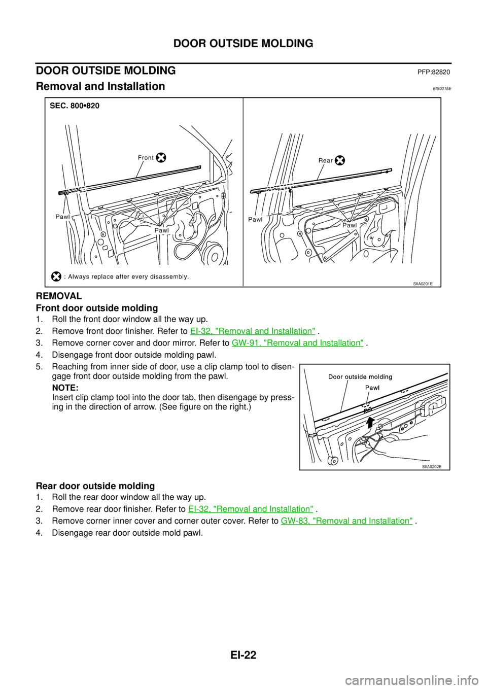
Front door outside molding
1. Roll the front door window all the way up.
2. Remove front door finisher. Refer to EI-32, "
Removal and Installation" .
3. Remove corner cover and door mirror. Refer to GW-91, "
Removal and Installation" .
4. Disengage front door outside molding pawl.
5. Reaching from inner side of door, use a clip clamp tool to disen-
gage front door outside molding from the pawl.
NOTE:
Insert clip clamp tool into the door tab, then disengage by press-
ing in the direction of arrow. (See figure on the right.)
Rear door outside molding
1. Roll the rear door window all the way up.
2. Remove rear door finisher. Refer to EI-32, "
Removal and Installation" .
3. Remove corner inner cover and corner outer cover. Refer to GW-83, "
Removal and Installation" .
4. Disengage rear door outside mold pawl.
SIIA0201E
SIIA0202E
Page 3337 of 4179
HEADLINING
EI-39
C
D
E
F
G
H
J
K
L
MA
B
EI
HEADLININGPFP:73910
Removal and InstallationEIS000ND
REMOVAL
1. Remove front pillar and center pillar garnishes. Refer to EI-35, "Removal and Installation" .
2. Remove body side welt. Refer to EI-35, "
Removal and Installation" .
3. Remove rear pillar finisher. Refer to EI-35, "
Removal and Installation" .
SIIA0223E
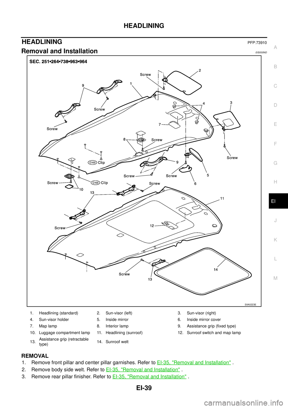
1. Headlining (standard) 2. Sun-visor (left) 3. Sun-visor (right)
4. Sun-visor holder 5. Inside mirror 6. Inside mirror cover
7. Map lamp 8. Interior lamp 9. Assistance grip (fixed type)
10. Luggage compartment lamp 11. Headlining (sunroof) 12. Sunroof switch and map lamp
13.Assistance grip (retractable
type)14. Sunroof welt
Page 3338 of 4179
EI-40
HEADLINING
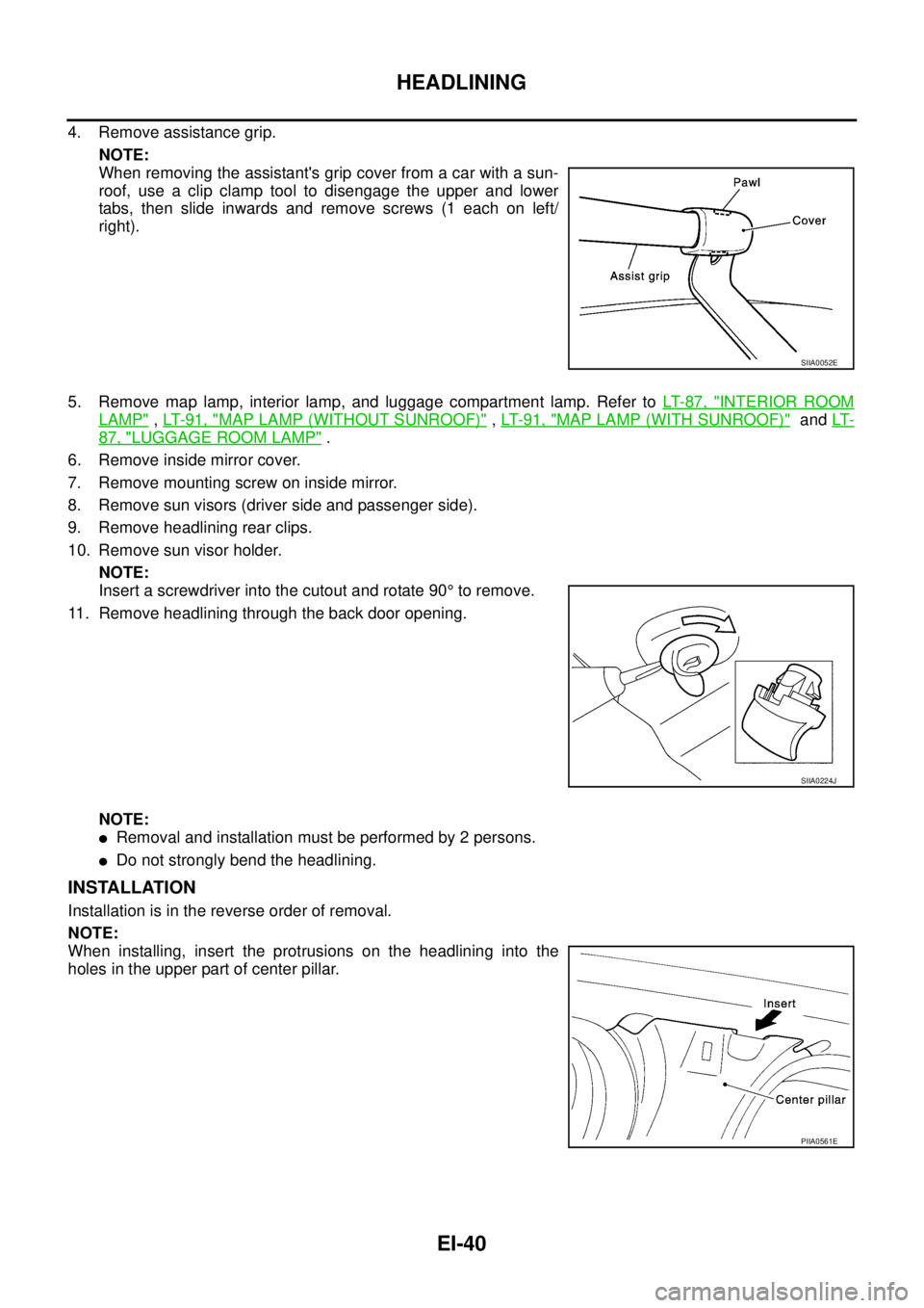
4. Remove assistance grip.
NOTE:
When removing the assistant's grip cover from a car with a sun-
roof, use a clip clamp tool to disengage the upper and lower
tabs, then slide inwards and remove screws (1 each on left/
right).
5. Remove map lamp, interior lamp, and luggage compartment lamp. Refer to LT- 8 7 , "
INTERIOR ROOM
LAMP" , LT- 9 1 , "MAP LAMP (WITHOUT SUNROOF)" , LT- 9 1 , "MAP LAMP (WITH SUNROOF)" and LT-
87, "LUGGAGE ROOM LAMP" .
6. Remove inside mirror cover.
7. Remove mounting screw on inside mirror.
8. Remove sun visors (driver side and passenger side).
9. Remove headlining rear clips.
10. Remove sun visor holder.
NOTE:
Insert a screwdriver into the cutout and rotate 90° to remove.
11. Remove headlining through the back door opening.
NOTE:
�Removal and installation must be performed by 2 persons.
�Do not strongly bend the headlining.
INSTALLATION
Installation is in the reverse order of removal.
NOTE:
When installing, insert the protrusions on the headlining into the
holes in the upper part of center pillar.
SIIA0052E
SIIA0224J
PIIA0561E
Page 3556 of 4179
ATC-160
REFRIGERANT LINES
Checking for Refrigerant LeaksEJS000VJ
Perform a visual inspection of all refrigeration parts, fittings, hoses and components for signs of A/C lubricant
leakage, damage and corrosion. A/C lubricant leakage may indicate an area of refrigerant leakage. Allow
extra inspection time in these areas when using either an electronic refrigerant leak detector or fluorescent
dye leak detector.
If dye is observed, confirm the leak with an electronic refrigerant leak detector. It is possible a prior leak was
repaired and not properly cleaned.
When searching for leaks, do not stop when one leak is found but continue to check for additional leaks at all
system components and connections.
When searching for refrigerant leaks using an electronic leak detector, move the probe along the suspected
leak area at 1 to 2 inches per second and no further than 1/4 inch from the component.
CAUTION:
Moving the electronic leak detector probe slower and closer to the suspected leak area will improve
the chances of finding a leak.
Checking System for Leaks Using the Fluorescent Leak DetectorEJS000VK
1. Check A/C system for leaks using the UV lamp and safety goggles (J-42220) in a low sunlight area (area
without windows preferable). Illuminate all components, fittings and lines. The dye will appear as a bright
green/yellow area at the point of leakage. Fluorescent dye observed at the evaporator drain opening indi-
cates an evaporator core assembly (tubes, core or expansion valve) leak.
2. If the suspected area is difficult to see, use an adjustable mirror or wipe the area with a clean shop rag or
cloth, with the UV lamp for dye residue.
3. After the leak is repaired, remove any residual dye using dye cleaner (J-43872) to prevent future misdiag-
nosis.
4. Perform a system performance check and verify the leak repair with an approved electronic refrigerant
leak detector.
NOTE:
Other gases in the work area or substances on the A/C components, for example, anti-freeze, windshield
washer fluid, solvents and lubricants, may falsely trigger the leak detector. Make sure the surfaces to be
checked are clean.
Clean with a dry cloth or blow off with shop air.
Do not allow the sensor tip of the detector to contact with any substance. This can also cause false readings
and may damage the detector.
Dye InjectionEJS000VL
(This procedure is only necessary when recharging the system or when the compressor has seized and was
replaced.)
1. Check A/C system static (at rest) pressure. Pressure must be at least 345 kPa (3.45 bar, 3.52 kg/cm
2 , 50
psi).
2. Pour one bottle (1/4 ounce / 7.4 cc) of the A/C refrigerant dye into the injector tool (J-41459).
3. Connect the injector tool to the A/C LOW-PRESSURE side service fitting.
4. Start engine and switch A/C ON.
5. When the A/C operating (compressor running), inject one bottle (1/4 ounce / 7.4 cc) of fluorescent dye
through the low-pressure service valve using dye injector tool J-41459 (refer to the manufacture's operat-
ing instructions).
6. With the engine still running, disconnect the injector tool from the service fitting.
CAUTION:
Be careful the A/C system or replacing a component, pour the dye directly into the open system con-
nection and proceed with the service procedures.
7. Operate the A/C system for a minimum of 20 minutes to mix the dye with the system oil. Depending on the
leak size, operating conditions and location of the leak, it may take from minutes to days for the dye to
penetrate a leak and become visible.