Page 632 of 3066
ATC-54
TROUBLE DIAGNOSIS
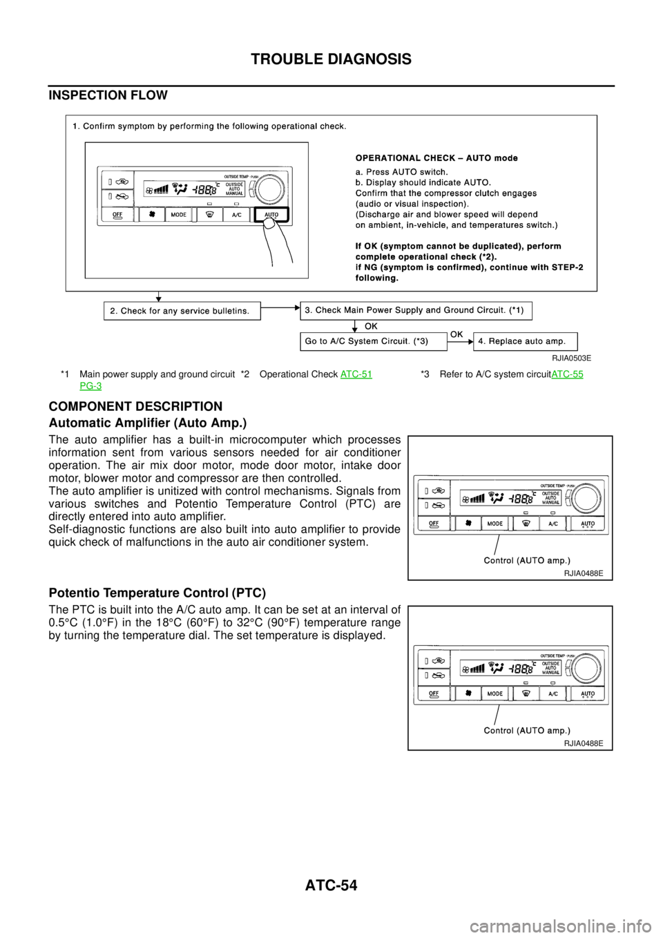
INSPECTION FLOW
COMPONENT DESCRIPTION
Automatic Amplifier (Auto Amp.)
The auto amplifier has a built-in microcomputer which processes
information sent from various sensors needed for air conditioner
operation. The air mix door motor, mode door motor, intake door
motor, blower motor and compressor are then controlled.
The auto amplifier is unitized with control mechanisms. Signals from
various switches and Potentio Temperature Control (PTC) are
directly entered into auto amplifier.
Self-diagnostic functions are also built into auto amplifier to provide
quick check of malfunctions in the auto air conditioner system.
Potentio Temperature Control (PTC)
The PTC is built into the A/C auto amp. It can be set at an interval of
0.5°C(1.0°F) in the 18°C(60°F) to 32°C(90°F) temperature range
by turning the temperature dial. The set temperature is displayed.
*1 Main power supply and ground circuit
PG-3*2 Operational CheckAT C - 5 1*3 Refer to A/C system circuitAT C - 5 5
RJIA0503E
RJIA0488E
RJIA0488E
Page 635 of 3066
TROUBLE DIAGNOSIS
ATC-57
C
D
E
F
G
H
I
K
L
MA
B
AT C
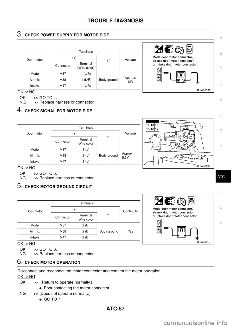
3.CHECK POWER SUPPLY FOR MOTOR SIDE
OK or NG
OK >> GO TO 4.
NG >> Replace harness or connector.
4.CHECK SIGNAL FOR MOTOR SIDE
OK or NG
OK >> GO TO 5.
NG >> Replace harness or connector.
5.CHECK MOTOR GROUND CIRCUIT
OK or NG
OK >> GO TO 6.
NG >> Replace harness or connector.
6.CHECK MOTOR OPERATION
Disconnect and reconnect the motor connector and confirm the motor operation.
OK or NG
OK >> (Return to operate normally.)
lPoor contacting the motor connector
NG >> (Does not operate normally.)
lGO TO 7
Door motorTe r m i n a l s
Voltag e (+)
(-)
ConnectorTe r m i n a l
(Wire color)
Mode M37 1 (L/R)
Body groundApprox.
12V Air mix M38 1 (L/R)
Intake M47 1 (L/R)
RJIA0509E
Door motorTe r m i n a l s
Vo l ta g e (+)
(-)
ConnectorTe r m i n a l
(Wire color)
Mode M37 3 (L)
Body groundApprox.
5.5V Air mix M38 3 (L)
Intake M47 3 (L)
RJIA0610E
Door motorTe r m i n a l s
Continuity (+)
(-)
ConnectorTe r m i n a l
(Wire color)
Mode M37 2 (B)
Body ground Yes Air mix M38 2 (B)
Intake M47 2 (B)
RJIA0511E
Page 638 of 3066
ATC-60
TROUBLE DIAGNOSIS
SYSTEM DESCRIPTION
Component Parts
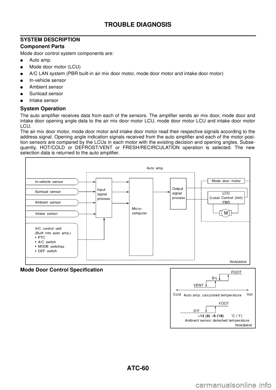
Mode door control system components are:
lAuto amp.
lMode door motor (LCU)
lA/C LAN system (PBR built-in air mix door motor, mode door motor and intake door motor)
lIn-vehicle sensor
lAmbient sensor
lSunload sensor
lIntake sensor
System Operation
The auto amplifier receives data from each of the sensors. The amplifier sends air mix door, mode door and
intake door opening angle data to the air mix door motor LCU, mode door motor LCU and intake door motor
LCU.
The air mix door motor, mode door motor and intake door motor read their respective signals according to the
address signal. Opening angle indication signals received from the auto amplifier and each of the motor posi-
tion sensors are compared by the LCUs in each motor with the existing decision and opening angles. Subse-
quently, HOT/COLD or DEFROST/VENT or FRESH/RECIRCULATION operation is selected. The new
selection data is returned to the auto amplifier.
Mode Door Control Specification
RHA045HA
RHA384HA
Page 641 of 3066
TROUBLE DIAGNOSIS
ATC-63
C
D
E
F
G
H
I
K
L
MA
B
AT C
lIn-vehicle sensor
lAmbient sensor
lSunload sensor
lIntake sensor
System Operation
The auto amplifier receives data from each of the sensors. The amplifier sends air mix door, mode door and
intake door motor opening angle data to the air mix door motor LCU, mode door motor LCU and intake door
motor LCU.
The air mix door motor, mode door motor and intake door motor read their respective signals according to the
address signal. Opening angle indication signals received from the auto amplifier and each of the motor posi-
tion sensors are compared by the LCUs in each motor with the existing decision and opening angles. Subse-
quently, HOT/COLD or DEFROST/VENT or FRESH/RECIRCULATION operation is selected. The new
selection data is returned to the auto amplifier.
Air Mix Door Control Specification
RHA424GB
RHA457H
Page 644 of 3066
ATC-66
TROUBLE DIAGNOSIS
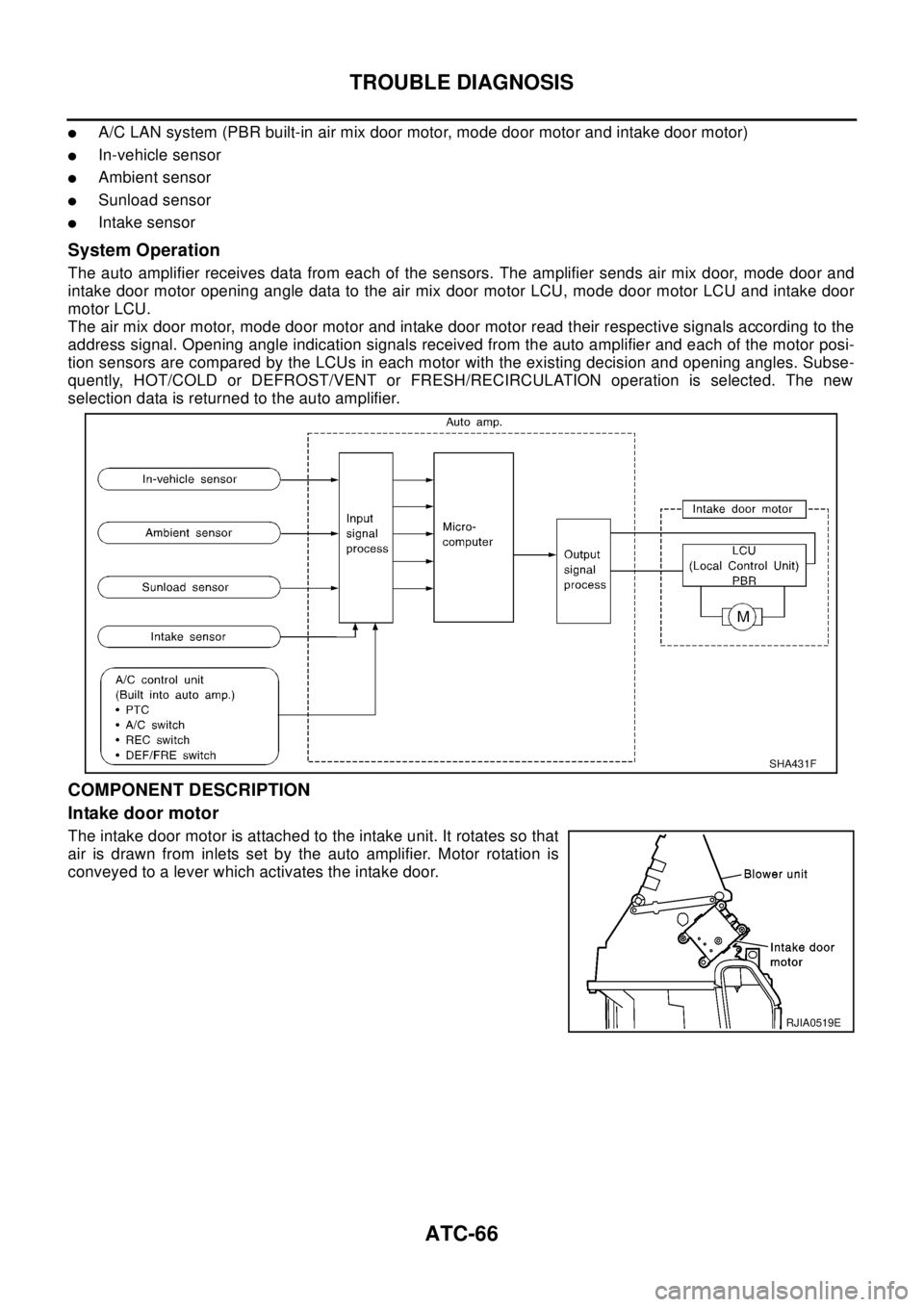
lA/C LAN system (PBR built-in air mix door motor, mode door motor and intake door motor)
lIn-vehicle sensor
lAmbient sensor
lSunload sensor
lIntake sensor
System Operation
The auto amplifier receives data from each of the sensors. The amplifier sends air mix door, mode door and
intake door motor opening angle data to the air mix door motor LCU, mode door motor LCU and intake door
motor LCU.
The air mix door motor, mode door motor and intake door motor read their respective signals according to the
address signal. Opening angle indication signals received from the auto amplifier and each of the motor posi-
tion sensors are compared by the LCUs in each motor with the existing decision and opening angles. Subse-
quently, HOT/COLD or DEFROST/VENT or FRESH/RECIRCULATION operation is selected. The new
selection data is returned to the auto amplifier.
COMPONENT DESCRIPTION
Intake door motor
The intake door motor is attached to the intake unit. It rotates so that
air is drawn from inlets set by the auto amplifier. Motor rotation is
conveyed to a lever which activates the intake door.
SHA431F
RJIA0519E
Page 653 of 3066
TROUBLE DIAGNOSIS
ATC-75
C
D
E
F
G
H
I
K
L
MA
B
AT C
Low Temperature Protection Control (With Gasoline Engine)
Auto amplifier will turn the compressor ON or OFF as determined by
a signal detected by ambient sensor.
When ambient temperatures are greater than -2°C(28°F), the com-
pressor turns ON. The compressor turns OFF when ambient temper-
atures are less than -5°C(23°F).
Evaporator Freeze Protection Control (With Diesel Engine)
Auto amplifier will turn the compressor ON or OFF as determined by
a signal detected by intake sensor.
When intake temperatures are greater than 4°C(39°F), the com-
pressor turns ON. The compressor turns OFF when intake tempera-
tures are less than 2.5°C (36.5°F).
DIAGNOSTIC PROCEDURE
SYMPTOM: Magnet clutch does not engage when A/C switch is ON.
RHA094GB
RJIA0534E
RJIA0535E
Page 755 of 3066
POWERDOORLOCKSYSTEM
BL-11
C
D
E
F
G
H
J
K
L
MA
B
BL
POWER DOOR LOCK SYSTEMPFP:24814
System DescriptionEIS001SE
OPERATION
Power door lock/unlock operation by door key cylinder
lWith the key inserted into driver's door key cylinder, turning it to LOCK will lock all doors.
lWith the key inserted into driver's door key cylinder, turning it to UNLOCK will unlock all doors.
Power door lock/unlock operation by lock/unlock switch
lWith lock/unlock switch setting to LOCK will lock all doors.
lWith lock/unlock switch setting to UNLOCK will unlock all doors.
Key reminder system
lIf the ignition key is in the ignition key cylinder and driver door is open, setting lock/unlock switch, lock
knob, key or multi-remote controller to “LOCK” locks the door once but then immediately unlocks all doors.
(signal from door unlock sensor driver side)
Component Parts and Harness Connector LocationEIS001R2
PIIA0584E
Page 762 of 3066
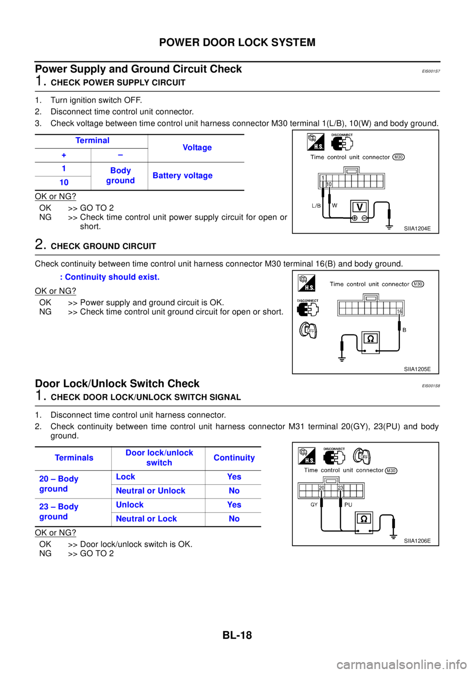
BL-18
POWER DOOR LOCK SYSTEM
Power Supply and Ground Circuit Check
EIS001S7
1.CHECK POWER SUPPLY CIRCUIT
1. Turn ignition switch OFF.
2. Disconnect time control unit connector.
3. Check voltage between time control unit harness connector M30 terminal 1(L/B), 10(W) and body ground.
OK or NG?
OK >> GO TO 2
NG >> Check time control unit power supply circuit for open or
short.
2.CHECK GROUND CIRCUIT
Check continuity between time control unit harness connector M30 terminal 16(B) and body ground.
OK or NG?
OK >> Power supply and ground circuit is OK.
NG >> Check time control unit ground circuit for open or short.
Door Lock/Unlock Switch CheckEIS001S8
1.CHECKDOORLOCK/UNLOCKSWITCHSIGNAL
1. Disconnect time control unit harness connector.
2. Check continuity between time control unit harness connector M31 terminal 20(GY), 23(PU) and body
ground.
OK or NG?
OK >> Door lock/unlock switch is OK.
NG >> GO TO 2Te r m i n a l
Vo l ta g e
+–
1
Body
groundBattery voltage
10
SIIA1204E
: Continuity should exist.
SIIA1205E
Te r m i n a l sDoor lock/unlock
switchContinuity
20 – Body
groundLock Yes
Neutral or Unlock No
23 – Body
groundUnlock Yes
Neutral or Lock No
SIIA1206E