Page 432 of 3066
![NISSAN X-TRAIL 2003 Electronic Repair Manual AT-426
[ALL]
BATT/FLUID TEMP SEN (A/T FLUID TEMP SENSOR CIRCUIT AND TCM POW-
ER SOURCE)
BATT/FLUID TEMP SEN (A/T FLUID TEMP SENSOR CIRCUIT AND TCM POWER
SOURCE)
PFP:31940
DescriptionECS004U8
The A/T f NISSAN X-TRAIL 2003 Electronic Repair Manual AT-426
[ALL]
BATT/FLUID TEMP SEN (A/T FLUID TEMP SENSOR CIRCUIT AND TCM POW-
ER SOURCE)
BATT/FLUID TEMP SEN (A/T FLUID TEMP SENSOR CIRCUIT AND TCM POWER
SOURCE)
PFP:31940
DescriptionECS004U8
The A/T f](/manual-img/5/57402/w960_57402-431.png)
AT-426
[ALL]
BATT/FLUID TEMP SEN (A/T FLUID TEMP SENSOR CIRCUIT AND TCM POW-
ER SOURCE)
BATT/FLUID TEMP SEN (A/T FLUID TEMP SENSOR CIRCUIT AND TCM POWER
SOURCE)
PFP:31940
DescriptionECS004U8
The A/T fluid temperature sensor detects the A/T fluid temperature
and sends a signal to the TCM.
CONSULT-II REFERENCE VALUE IN DATA MONITOR MODE
Remarks: Specification data are reference values.
TCM TERMINALS AND REFERENCE VALUE
Remarks: Specification data are reference values.
SCIA0735E
SAT021J
Monitor item Condition Specification (Approximately)
A/T fluid temperature sensorCold [20°C(68°F)]
¯
Hot [80°C(176°F)]1.5V
¯
0.5V2.5 kW
¯
0.3 kW
Te r m i -
nal No.Wire color Item ConditionJudgement stan-
dard
(Approx.)
10 BR/W Power source
orWhen turning ignition switch to “ON”. Battery voltage
When turning ignition switch to
“OFF”.0V
19 BR/W Power source Same as No. 10
28 R/BPower source
(Memory back-up)
orWhen turning ignition switch to
“OFF”.Battery voltage
When turning ignition switch to “ON”. Battery voltage
42 BGround
(A/T fluid tempera-
ture sensor)———
47 BRA/T fluid tempera-
ture sensorWhen ATF temperature is 20°C
(68°F).1.5V
When ATF temperature is 80°C
(176°F).0.5V
Page 436 of 3066
![NISSAN X-TRAIL 2003 Electronic Repair Manual AT-430
[ALL]
BATT/FLUID TEMP SEN (A/T FLUID TEMP SENSOR CIRCUIT AND TCM POW-
ER SOURCE)
3.CHECK INPUT SIGNAL OF A/T FLUID TEMPERATURE SENSOR (WITH CONSULT-II)
With CONSULT-II
1. Start engine.
2. Selec NISSAN X-TRAIL 2003 Electronic Repair Manual AT-430
[ALL]
BATT/FLUID TEMP SEN (A/T FLUID TEMP SENSOR CIRCUIT AND TCM POW-
ER SOURCE)
3.CHECK INPUT SIGNAL OF A/T FLUID TEMPERATURE SENSOR (WITH CONSULT-II)
With CONSULT-II
1. Start engine.
2. Selec](/manual-img/5/57402/w960_57402-435.png)
AT-430
[ALL]
BATT/FLUID TEMP SEN (A/T FLUID TEMP SENSOR CIRCUIT AND TCM POW-
ER SOURCE)
3.CHECK INPUT SIGNAL OF A/T FLUID TEMPERATURE SENSOR (WITH CONSULT-II)
With CONSULT-II
1. Start engine.
2. Select “TCM INPUT SIGNALS” in “DATA MONITOR” mode for “A/T” with CONSULT-II.
3. Read out the value of “FLUID TEMP SE”.
OK or NG
OK >> GO TO 5
NG >> Check the following item:
lHarness for short or open between TCM, ECM and
terminal cord assembly (Main harness)
lGround circuit for ECM
Refer to “”, “TROUBLE DIAGNOSIS FOR POWER
SUPPLY”.
4.CHECK INPUT SIGNAL OF A/T FLUID TEMPERATURE SENSOR (WITHOUT CONSULT-II)
Without CONSULT-II
1. Start engine.
2. Check voltage between TCM terminal 47 and ground while warming up A/T.
3. Turn ignition switch to “OFF” position.
4. Disconnect TCM harness connector.
5. Check resistance between terminal 42 and ground.
OK or NG
OK >> GO TO 5
NG >> Check the following item:
lHarness for short or open between TCM, ECM and
terminal cord assembly (Main harness)
lGround circuit for ECM
Refer to “”, “TROUBLE DIAGNOSIS FOR POWER
SUPPLY”. Vo l ta g e
Cold [20°C(68°F)]®Hot [80°C(176°F)] :
Approximately 1.5V®0.5V
SAT614J
Vo l ta g e
Cold [20°C(68°F)]®Hot [80°C(176°F)] :
Approximately 1.5V®0.5V
SCIA0738E
Continuity should exist.
SCIA0739E
Page 446 of 3066
AT-440
[ALL]
LINE PRESSURE SOLENOID VALVE
3.CHECK POWER SOURCE CIRCUIT
1. Turn ignition switch to “OFF” position.
2. Check resistance between terminal 4 and TCM harness connector terminal 1.
If OK, check harness for short to ground and short to power.
3. Reinstall any part removed.
OK or NG
OK >> GO TO 4
NG >> Repair open circuit or short to ground or short to power
in harness or connectors.
4.CHECK DTC
Perform Self-diagnosis Code confirmation procedure,AT-436, "
LINE PRESSURE SOLENOID VALVE".
OK or NG
OK >>INSPECTION END
NG >> 1. Perform TCM input/output signal inspection.
2. If NG, recheck TCM pin terminals for damage or loose connection with harness connector. Resistance : Approx. 0W
SCIA0743E
Page 451 of 3066
CAN CAMMUNICATION LINE
AT-445
[ALL]
D
E
F
G
H
I
J
K
L
MA
B
AT
Diagnostic ProcedureECS004UN
1.CHECK CAN COMMUNICATION CIRCUIT
With CONSULT-II
1. Turn ignition switch to "ON" position. (Do not start engine.)
2. Select "DATA MONITOR" mode for "A/T" with CONSULT-II.
3. The "CON COMM CIRCUIT" is detected.
Ye s o r N o ?
Yes >> Print out CONSULT-II screen, GO TO 2.
NG >> INSPECTION END
2.CHECK CAN COMMUNICATION SIGNALS
With CONSULT-II
1. Turn ignition switch to "ON" position. (Do not start engine.)
2. Select "CAN COMM SIGNALS" in "DATA MONITOR" mode for "A/T" with CONSULT-II.
>> Print out CONSULT-II screen, go toLAN-5, "
CAN SYSTEM (FOR A/T MODELS)"
CAN Communication Signals
PCIA0061E
Normal conditions Abnormal conditions (examples)
CAN COMM : OK CAN COMM : OK
CANCIRC1:OK CANCIRC1:UNKWN
CANCIRC2:OK CANCIRC2:UNKWN
CANCIRC3:OK CANCIRC3:UNKWN
CANCIRC4:OK CANCIRC4:UNKWN
CANCIRC5:UNKWN CANCIRC5:UNKWN
Page 455 of 3066
![NISSAN X-TRAIL 2003 Electronic Repair Manual A/T SHIFT LOCK SYSTEM
AT-449
[ALL]
D
E
F
G
H
I
J
K
L
MA
B
AT
4.CHECK INPUT SIGNAL (A/T DEVICE)
Turn ignition switch to “ON” position.
(Do not start engine.)
lCheck voltage between A/T device harne NISSAN X-TRAIL 2003 Electronic Repair Manual A/T SHIFT LOCK SYSTEM
AT-449
[ALL]
D
E
F
G
H
I
J
K
L
MA
B
AT
4.CHECK INPUT SIGNAL (A/T DEVICE)
Turn ignition switch to “ON” position.
(Do not start engine.)
lCheck voltage between A/T device harne](/manual-img/5/57402/w960_57402-454.png)
A/T SHIFT LOCK SYSTEM
AT-449
[ALL]
D
E
F
G
H
I
J
K
L
MA
B
AT
4.CHECK INPUT SIGNAL (A/T DEVICE)
Turn ignition switch to “ON” position.
(Do not start engine.)
lCheck voltage between A/T device harness terminal 7 and ground.
OK or NG
OK >> GO TO 5
NG >> Check the following items:
1. Harness for short and open between battery and stop
lamp switch harness connector 1.
2. Harness for short or open between stop lamp switch harness connector 2 and A/T device har-
ness connector 7.
3. Fuse
4. Stop lamp switch (Refer toAT- 4 5 0 , "
A/T DEVICE CHECK".)
5.CHECK GROUND CIRCUIT
1. Turn ignition switch to “OFF” position.
2. Disconnect A/T device harness connector.
3. Check continuity between A/T device harness terminal 6 and ground.
If OK, check harness for short to ground and short to power.
OK or NG
OK >> GO TO 6
NG >> Repair open circuit or short to ground or short to power
in harness or connectors. Voltage:
Brake pedal depressd:
Battery voltage
Brake pedal released:
0V
SCIA0783E
Continuity should exist.
SCIA0784E
Page 456 of 3066
AT-450
[ALL]
A/T SHIFT LOCK SYSTEM
6.CHECK RELAY CIRCUIT
1. Turn ignition switch to ON.
Check voltage between terminal 7 - 6 and 5 - 6.
OK or NG
OK >> GO TO 7
NG >> Replace A/T device.
7.CHECKPARKPOSITIONSWITCH
Refer toAT-450, "
A/T DEVICE CHECK".
OK or NG
OK >> GO TO 8
NG >> Replace A/T device.
8.CHECK SHIFT LOCK SOLENOID
Refer toAT-450, "
A/T DEVICE CHECK".
OK or NG
OK >> GO TO 9
NG >> Replace A/T device.
9.SHIFT LOCK OPERATION
1. Reconnect shift lock harness connector.
2. Turn ignition switch from “OFF” to “ON” position. (Do not start engine.)
3. Recheck shift lock operation.
OK or NG
OK >>INSPECTION END
NG >> 1. Perform A/T device input/output signal inspection test.
2. If NG, recheck harness connector connection.
A/T DEVICE CHECK
1. Shift Lock Solenoid
lCheck operation sound.
When ignition switch is turned to “ON” position and selector lever is set in “P” position.
SCIA0785E
Brake pedal Operation sound
Depressed Yes
Released No
Page 602 of 3066

ATC-24
AIR CONDITIONER CONTROL
AIR CONDITIONER CONTROL
PFP:27500
Overview Air Conditioner LAN Control SystemEJS000TI
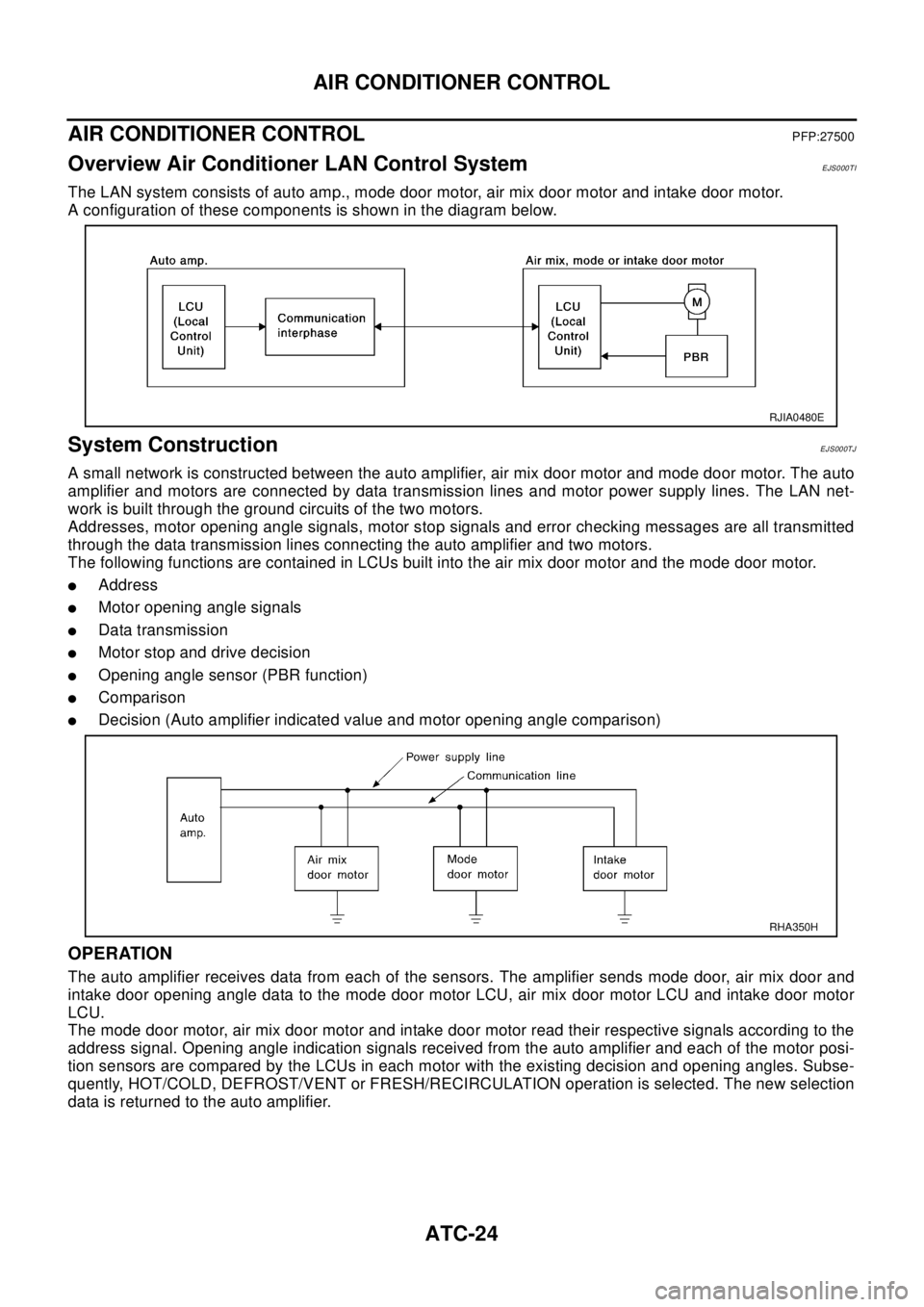
The LAN system consists of auto amp., mode door motor, air mix door motor and intake door motor.
A configuration of these components is shown in the diagram below.
System ConstructionEJS000TJ
A small network is constructed between the auto amplifier, air mix door motor and mode door motor. The auto
amplifier and motors are connected by data transmission lines and motor power supply lines. The LAN net-
work is built through the ground circuits of the two motors.
Addresses, motor opening angle signals, motor stop signals and error checking messages are all transmitted
through the data transmission lines connecting the auto amplifier and two motors.
The following functions are contained in LCUs built into the air mix door motor and the mode door motor.
lAddress
lMotor opening angle signals
lData transmission
lMotor stop and drive decision
lOpening angle sensor (PBR function)
lComparison
lDecision (Auto amplifier indicated value and motor opening angle comparison)
OPERATION
The auto amplifier receives data from each of the sensors. The amplifier sends mode door, air mix door and
intake door opening angle data to the mode door motor LCU, air mix door motor LCU and intake door motor
LCU.
The mode door motor, air mix door motor and intake door motor read their respective signals according to the
address signal. Opening angle indication signals received from the auto amplifier and each of the motor posi-
tion sensors are compared by the LCUs in each motor with the existing decision and opening angles. Subse-
quently, HOT/COLD, DEFROST/VENT or FRESH/RECIRCULATION operation is selected. The new selection
data is returned to the auto amplifier.
RJIA0480E
RHA350H
Page 620 of 3066

ATC-42
TROUBLE DIAGNOSIS
Self-diagnosis Function
EJS001GX
DESCRIPTION
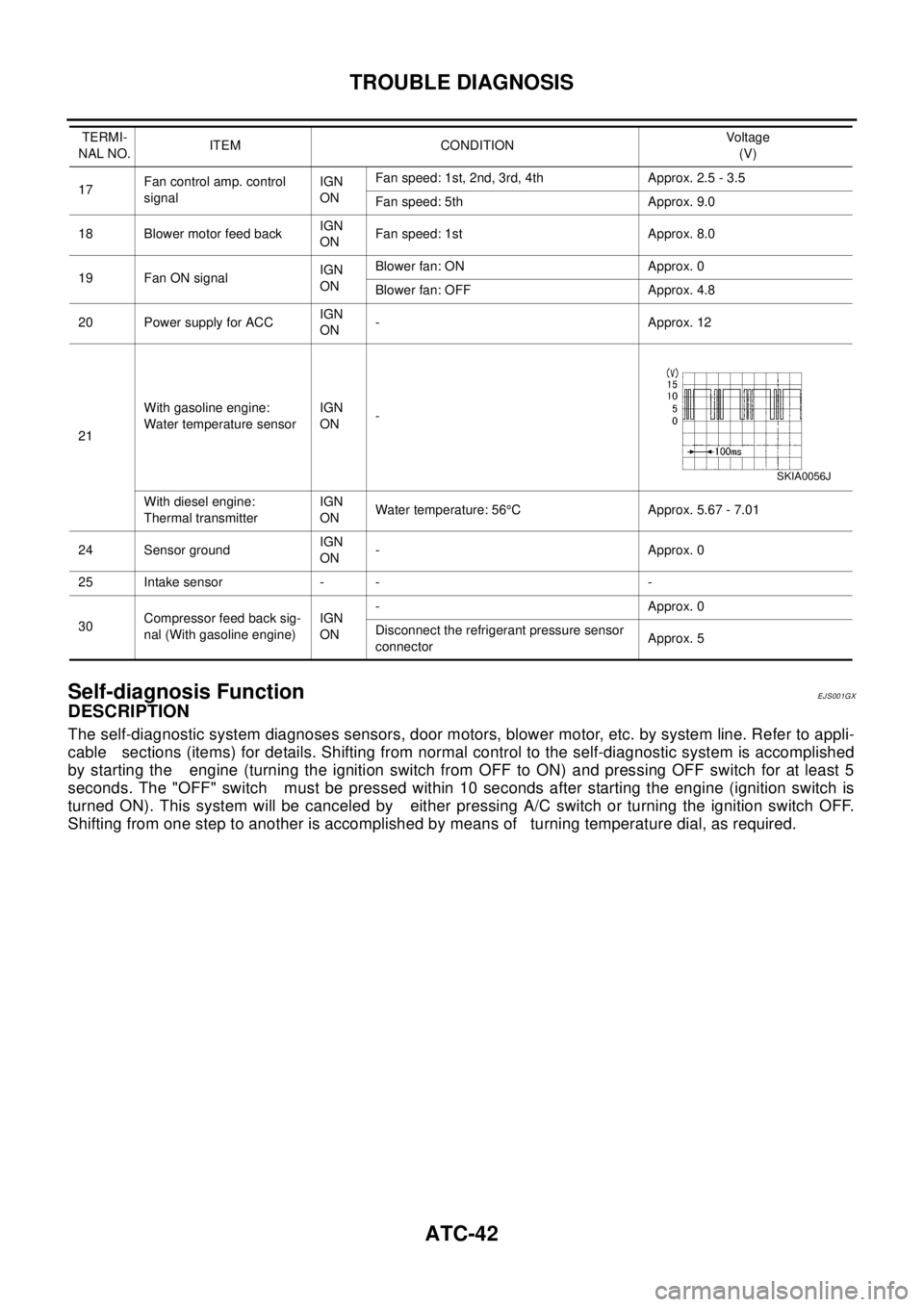
The self-diagnostic system diagnoses sensors, door motors, blower motor, etc. by system line. Refer to appli-
cable sections (items) for details. Shifting from normal control to the self-diagnostic system is accomplished
by starting the engine (turning the ignition switch from OFF to ON) and pressing OFF switch for at least 5
seconds. The "OFF" switch must be pressed within 10 seconds after starting the engine (ignition switch is
turned ON). This system will be canceled by either pressing A/C switch or turning the ignition switch OFF.
Shifting from one step to another is accomplished by means of turning temperature dial, as required.
17Fan control amp. control
signalIGN
ONFan speed: 1st, 2nd, 3rd, 4th Approx. 2.5 - 3.5
Fan speed: 5th Approx. 9.0
18 Blower motor feed backIGN
ONFan speed: 1st Approx. 8.0
19 Fan ON signalIGN
ONBlower fan: ON Approx. 0
Blower fan: OFF Approx. 4.8
20 Power supply for ACCIGN
ON-Approx.12
21With gasoline engine:
Water temperature sensorIGN
ON-
With diesel engine:
Thermal transmitterIGN
ONWater temperature: 56°C Approx. 5.67 - 7.01
24 Sensor groundIGN
ON-Approx.0
25 Intake sensor - - -
30Compressor feed back sig-
nal (With gasoline engine)IGN
ON-Approx.0
Disconnect the refrigerant pressure sensor
connectorApprox. 5 TERMI-
NAL NO.ITEM CONDITIONVo ltag e
(V)
SKIA0056J