2003 NISSAN X-TRAIL turn signal
[x] Cancel search: turn signalPage 947 of 3066
![NISSAN X-TRAIL 2003 Electronic Repair Manual TROUBLE DIAGNOSIS
BRC-79
[ESP/TCS/ABS]
C
D
E
G
H
I
J
K
L
MA
B
BRC
CAUTION:
If the memory cannot be erased, go to step 6.
10. Drive the vehicle at Approx. 30 km/h (19 MPH) and check that the ABS warnin NISSAN X-TRAIL 2003 Electronic Repair Manual TROUBLE DIAGNOSIS
BRC-79
[ESP/TCS/ABS]
C
D
E
G
H
I
J
K
L
MA
B
BRC
CAUTION:
If the memory cannot be erased, go to step 6.
10. Drive the vehicle at Approx. 30 km/h (19 MPH) and check that the ABS warnin](/manual-img/5/57402/w960_57402-946.png)
TROUBLE DIAGNOSIS
BRC-79
[ESP/TCS/ABS]
C
D
E
G
H
I
J
K
L
MA
B
BRC
CAUTION:
If the memory cannot be erased, go to step 6.
10. Drive the vehicle at Approx. 30 km/h (19 MPH) and check that the ABS warning lamp, ESP OFF indicator
lamp, and SLIP indicator lamp stay off.
CAUTION:
ESP OFF switch is not cancelled.
Self-Diagnostic Items to Result Mode
Self-Diagnostic item Malfunction detecting condition Check route
FR LH SENSOR – 1 Circuit of front LH wheel speed sensor is open.
Wheel speed sensor and
circuit. Refer toBRC-90
RR RH SENSOR – 1 Circuit of rear RH wheel speed sensor is open.
FR RH SENSOR – 1 Circuit of front RH wheel speed sensor is open.
RR LH SENSOR – 1 Circuit of rear LH wheel speed sensor is open.
FR LH SENSOR – 2Front LH wheel speed sensor is shorted or input signal is abnor-
mal.
RR RH SENSOR – 2Rear RH wheel speed sensor is shorted or input signal is abnor-
mal.
FR RH SENSOR – 2Front RH wheel speed sensor is shorted or input signal is abnor-
mal.
RR LH SENSOR – 2Rear LH wheel speed sensor is shorted or input signal is abnor-
mal.
MAIN RELAYDuring the actuator relay operation with OFF, when the actuator
relay turns ON. Or when the control line for the relay is shorted to
the ground.Actuator relay and cir-
cuit. Refer toBRC-102
During the actuator relay operation with ON, when the actuator
relay turns OFF. Or when the control line for the relay is open.
STOP LAMP SW Stop lamp switch circuit is open.Stop lamp switch and cir-
cuit. Refer toBRC-104
PRESS SEN CIRCUITPressure sensor signal line is open or shorted, or pressure sen-
sor is abnormal.Pressure sensor and cir-
cuit. Refer toBRC-93
ST ANGLE SEN CIRCUITNeutral position of the steering angle sensor is dislocated, or the
steering angle sensor is abnormal.Steering angle sensor
and circuit. Refer to
BRC-94
YA W R AT E S E N O RYaw rate sensor is abnormal, or the yaw rate sensor signal line is
open or shorted.Yaw rate/transverse
acceleration sensor and
circuit. Refer toBRC-95
Page 948 of 3066
![NISSAN X-TRAIL 2003 Electronic Repair Manual BRC-80
[ESP/TCS/ABS]
TROUBLE DIAGNOSIS
FR LH IN ABS SOLCircuit of the front LH wheel inlet solenoid valve is open or
shorted, or the control line is open or shorted to the power supply
or the ground.
NISSAN X-TRAIL 2003 Electronic Repair Manual BRC-80
[ESP/TCS/ABS]
TROUBLE DIAGNOSIS
FR LH IN ABS SOLCircuit of the front LH wheel inlet solenoid valve is open or
shorted, or the control line is open or shorted to the power supply
or the ground.](/manual-img/5/57402/w960_57402-947.png)
BRC-80
[ESP/TCS/ABS]
TROUBLE DIAGNOSIS
FR LH IN ABS SOLCircuit of the front LH wheel inlet solenoid valve is open or
shorted, or the control line is open or shorted to the power supply
or the ground.
Solenoid valve and cir-
cuit. Refer toBRC-97
FR LH OUT ABS SOLCircuit of the front LH wheel outlet solenoid valve is open or
shorted, or the control line is open or shorted to the power supply
or the ground.
RR RH IN ABS SOLCircuit of the rear RH wheel inlet solenoid valve is open or
shorted, or the control line is open or shorted to the power supply
or the ground.
RR RH OUT ABS SOLCircuit of the rear RH wheel outlet solenoid valve is open or
shorted, or the control line is open or shorted to the power supply
or the ground.
FR RH IN ABS SOLCircuit of the front RH wheel inlet solenoid valve is open or
shorted, or the control line is open or shorted to the power supply
or the ground.
FR RH OUT ABS SOLCircuit of the front RH wheel outlet solenoid valve is open or
shorted, or the control line is open or shorted to the power supply
or the ground.
RR LH IN ABS SOLCircuit of the rear LH wheel inlet solenoid valve is open or
shorted, or the control line is open or shorted to the power supply
or the ground.
RR LH OUT ABS SOLCircuit of the rear LH wheel outlet solenoid valve is open or
shorted, or the control line is open or shorted to the power supply
or the ground.
USV LINE [FL-RR]ESP switch-over solenoid valve 1 on the primary side is open cir-
cuit or shorted, or the control line is open or shorted to the power
supply or the ground.
ESP switch-over sole-
noid valve and circuit.
Refer toBRC-97
. USV LINE [FR-RL]ESP switch-over solenoid valve 1 on the secondary side is open
circuit or shorted, or the control line is open or shorted to the
power supply or the ground.
HSV LINE [FL-RR]ESP switch-over solenoid valve 2 on the primary side is open cir-
cuit or shorted, or the control line is open or shorted to the power
supply or the ground.
HSV LINE [FR-RL]ESP switch-over solenoid valve 2 on the secondary side is open
circuit or shorted, or the control line is open or shorted to the
power supply or the ground.
PUMP MOTOR
ACTUATOR RLY (note)During the actuator motor operation with ON, when the actuator
motor turns OFF. Or when the control line for actuator motor relay
is open.Actuator motor, motor
relay, and circuit. Refer
toBRC-100
During the actuator motor operation with OFF, when the actuator
motor turns ON. Or when the control line for relay is shorted to
ground.
ABS SENSOR
[ABNORMAL SIGNAL]Wheel speed sensor input is abnormal.Wheel speed sensor and
circuit. Refer toBRC-90
BATTERY VOLTAGE
[ABNORMAL]ESP/TCS/ABS control unit battery voltage is too low.ESP/TCS/ABS control
unit battery voltage cir-
cuit and ground circuit.
Refer toBRC-104
ST ANGLE SEN SIGNALNeutral position correction of steering angle sensor is not fin-
ished.Neutral position adjust-
ment of steering angle
sensor. Refer toBRC-
106
ST ANG SEN COM CIRCAN communication system or steering angle sensor is abnor-
mal.Steering angle sensor
and CAN communication
circuit. Refer toBRC-108
Self-Diagnostic item Malfunction detecting condition Check route
Page 949 of 3066
![NISSAN X-TRAIL 2003 Electronic Repair Manual TROUBLE DIAGNOSIS
BRC-81
[ESP/TCS/ABS]
C
D
E
G
H
I
J
K
L
MA
B
BRC
(note) “ACTUATOR RLY” on the CONSULT-II self-diagnosis results indicates the malfunction of the actuator motor relay and circuit.
NISSAN X-TRAIL 2003 Electronic Repair Manual TROUBLE DIAGNOSIS
BRC-81
[ESP/TCS/ABS]
C
D
E
G
H
I
J
K
L
MA
B
BRC
(note) “ACTUATOR RLY” on the CONSULT-II self-diagnosis results indicates the malfunction of the actuator motor relay and circuit.](/manual-img/5/57402/w960_57402-948.png)
TROUBLE DIAGNOSIS
BRC-81
[ESP/TCS/ABS]
C
D
E
G
H
I
J
K
L
MA
B
BRC
(note) “ACTUATOR RLY” on the CONSULT-II self-diagnosis results indicates the malfunction of the actuator motor relay and circuit.
DATA MONITOR
For details of the data monitor function, refer to the CONSULT-II Instruction Manual.
Procedure
1. Turn the ignition switch OFF.
2. Connect the CONSULT-II connector to the vehicle-side data link connector.
3. Turn the ignition switch ON.
4. Touch²START²on the display.
5. Touch²ABS²on the display.
CAUTION:
Just after the engine is started, or the ignition switch is
turned ON,²ABS²may not be displayed on the system
selection screen even if²START²is touched. In this case,
start the self-diagnosis again from step 2.
6. Touch²DATA MONITOR².
7. The data monitor item selection screen is displayed, and touch
one of “ECU INPUT SIGNALS” “MAIN SIGNALS”, “CAN DIAG
SUPPORT MNTR” or “SELECTION FROM MENU”. Refer to
BRC-82, "
Data Monitor Items to be Displayed".
8. Touch²START².
9. Screen of data monitor is displayed.
SIDE G-SEN CIRCUITSide G sensor is abnormal, or the signal line of side G sensor is
open or shorted.Yaw rate /Side G sensor
and circuit. Refer to
BRC-95
EMERGENCY BRAKEESP/TCS/ABS control unit malfunction (pressure increase is too
much or too little.)ESP/TCS/ABS control
unit. Refer toBRC-106
CONTROLLER FAILURE ESP/TCS/ABS internal malfunction of control unitESP/TCS/ABS control
unit. Refer toBRC-92
CAN COMM CIRCUIT
lCAN communication line is open or shorted.
lESP/TCS/ABS control unit internal malfunction.
lBattery voltage for EMC is interrupted instantaneously for
Approx. 0.5 seconds or more.Communication circuit
between ESP/TCS/ABS
control unit and units.
Refer toBRC-108
BR FLUID LEVEL LOWBrake fluid level drops or communication line between the ESP/
TCS/ABS control unit and the brake fluid level warning switch is
open or shorted.Communication circuit
between the ESP/TCS/
ABS control unit and the
brake fluid level warning
switch.
Reservoir tank fluid.
Refer toBRC-107
ENGINE SIGNAL 1-4, 6 Major engine components are abnormalEngine system. Refer to
BRC-92
Self-Diagnostic item Malfunction detecting condition Check route
SFIA0364E
SFIA0365E
Page 958 of 3066
![NISSAN X-TRAIL 2003 Electronic Repair Manual BRC-90
[ESP/TCS/ABS]
TROUBLE DIAGNOSIS
4. With the engine running, check the ESP OFF indicator lamp turns ON and OFF when the ESP OFF
switch turns ON and OFF. If it dose not operate in accordance with NISSAN X-TRAIL 2003 Electronic Repair Manual BRC-90
[ESP/TCS/ABS]
TROUBLE DIAGNOSIS
4. With the engine running, check the ESP OFF indicator lamp turns ON and OFF when the ESP OFF
switch turns ON and OFF. If it dose not operate in accordance with](/manual-img/5/57402/w960_57402-957.png)
BRC-90
[ESP/TCS/ABS]
TROUBLE DIAGNOSIS
4. With the engine running, check the ESP OFF indicator lamp turns ON and OFF when the ESP OFF
switch turns ON and OFF. If it dose not operate in accordance with the switch, check the ESP OFF switch
and the circuit.
5. Check that the ESP OFF indicator lamp turns OFF after Approx. 2 seconds delay when the ESP OFF
switch turned ON (The ESP/TCS system was not operated). If the ESP OFF indicator lamp does not turn
OFF in 10 seconds from the engine start, perform the self-diagnosis of ESP/TCS/ABS control unit.
Inspection 1 Wheel Speed Sensor and CircuitEFS001AB
Inspection procedure
1.SELF-DIAGNOSIS RESULT CHECK 1
Check the self-diagnosis results.
Are any self-diagnosis result items above indicated?
>> GO TO 2.
2.CHECK THE CONNECTOR
Remove connectors of the wheel speed sensor which is malfunctioning and the ESP/TCS/ABS control unit.
Check whether the deformation of terminal, or incorporate connection of connectors. Then, connect connec-
tors. In addition, check if the wheel speed sensor cable is damaged due to friction.
Does ABS warning lamp is out when driving 30km/h (49MPH) for Approx. One minute?
YES >> Check is completed.
NO >> GO TO 3.
Self-diagnosis results
CONSULT-II indication item
ABS SENSOR [ABNORMAL SIGNAL]
FR RH SENSOR – 1
FR RH SENSOR – 2
FR LH SENSOR – 1
FR LH SENSOR – 2
RR RH SENSOR – 1
RR RH SENSOR – 2
RR LH SENSOR – 1
RR LH SENSOR – 2
Page 1058 of 3066

DI-4
COMBINATION METERS (LHD MODELS)
COMBINATION METERS (LHD MODELS)
PFP:24810
System DescriptionEKS002Z7
UNIFIED CONTROL METER
lSpeedometer, odo/trip meter, tachometer, fuel gauge and water temperature gauge are controlled totally
by control unit built-in combination meter.
lDigital meter is adopted for odo/trip meter.*
*The record of the odo meter is kept even if the battery cable is disconnected. The record of the trip meter
is erased when the battery cable is disconnected.
lOdo/trip meter segment can be checked in diagnosis mode.
lMeter/gauge can be checked in diagnosis mode.
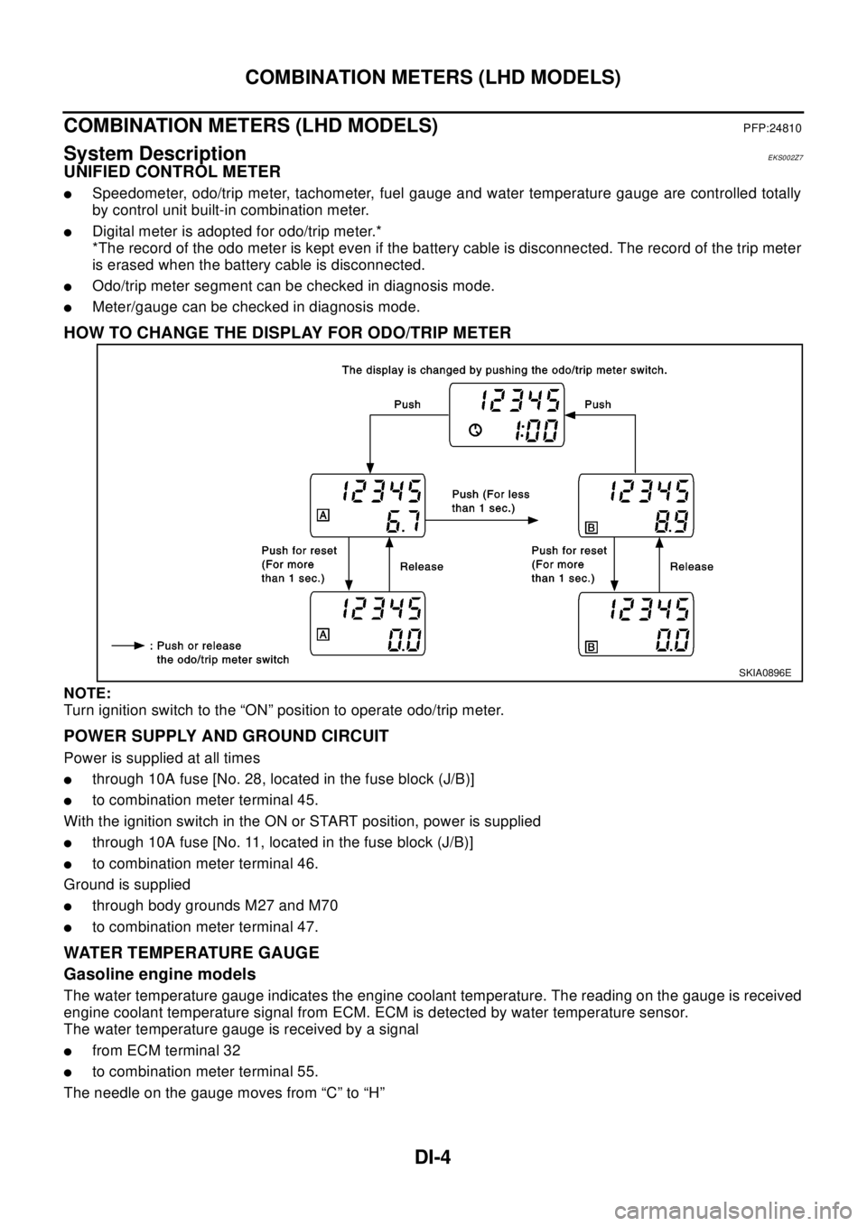
HOW TO CHANGE THE DISPLAY FOR ODO/TRIP METER
NOTE:
Turn ignition switch to the “ON” position to operate odo/trip meter.
POWER SUPPLY AND GROUND CIRCUIT
Power is supplied at all times
lthrough 10A fuse [No. 28, located in the fuse block (J/B)]
lto combination meter terminal 45.
With the ignition switch in the ON or START position, power is supplied
lthrough 10A fuse [No. 11, located in the fuse block (J/B)]
lto combination meter terminal 46.
Ground is supplied
lthrough body grounds M27 and M70
lto combination meter terminal 47.
WATER TEMPERATURE GAUGE
Gasoline engine models
The water temperature gauge indicates the engine coolant temperature. The reading on the gauge is received
engine coolant temperature signal from ECM. ECM is detected by water temperature sensor.
The water temperature gauge is received by a signal
lfrom ECM terminal 32
lto combination meter terminal 55.
The needle on the gauge moves from “C” to “H”
SKIA0896E
Page 1068 of 3066

DI-14
COMBINATION METERS (LHD MODELS)
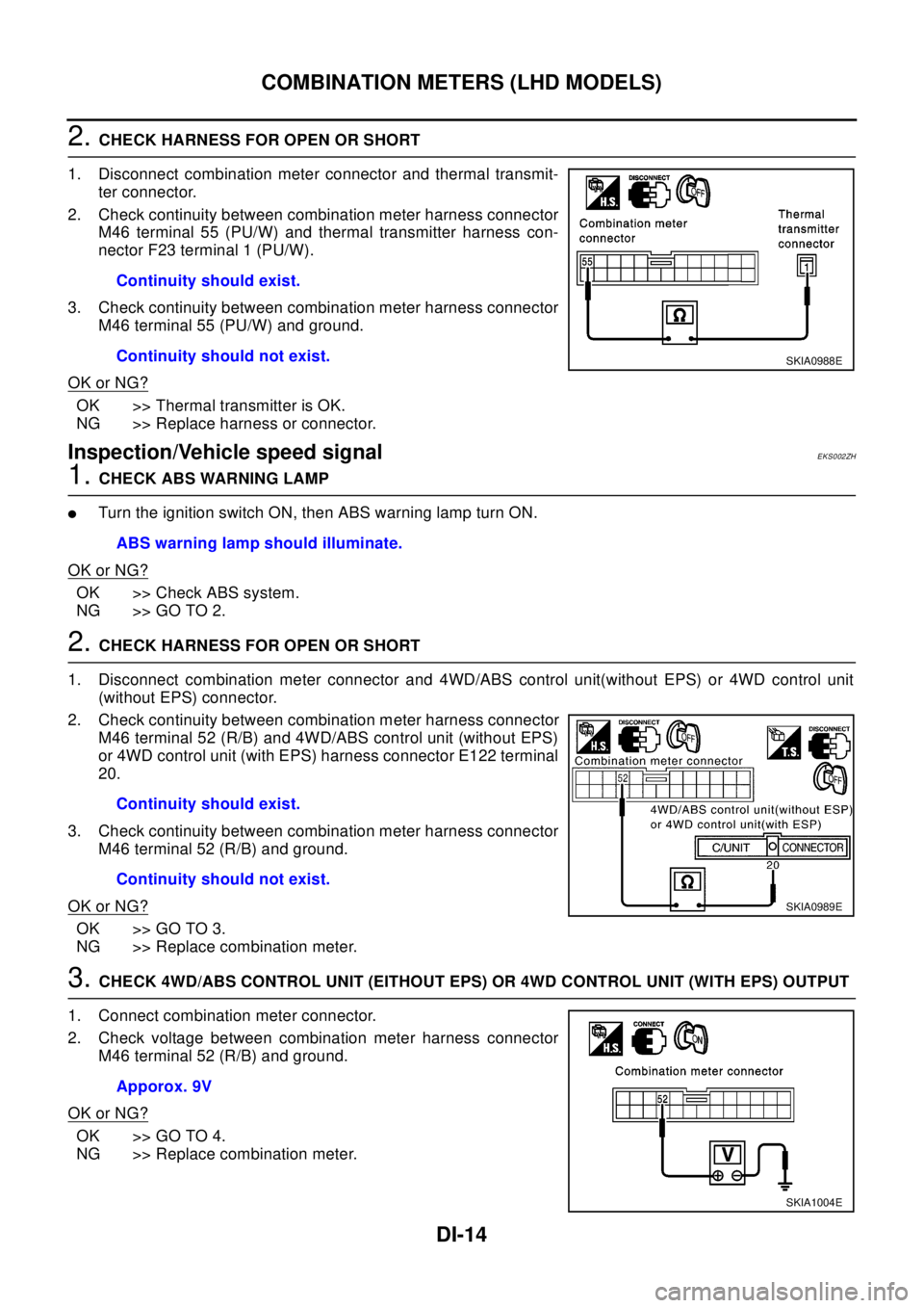
2.CHECK HARNESS FOR OPEN OR SHORT
1. Disconnect combination meter connector and thermal transmit-
ter connector.
2. Check continuity between combination meter harness connector
M46 terminal 55 (PU/W) and thermal transmitter harness con-
nector F23 terminal 1 (PU/W).
3. Check continuity between combination meter harness connector
M46 terminal 55 (PU/W) and ground.
OK or NG?
OK >> Thermal transmitter is OK.
NG >> Replace harness or connector.
Inspection/Vehicle speed signalEKS002ZH
1.CHECK ABS WARNING LAMP
lTurntheignitionswitchON,thenABSwarninglampturnON.
OK or NG?
OK >> Check ABS system.
NG >> GO TO 2.
2.CHECK HARNESS FOR OPEN OR SHORT
1. Disconnect combination meter connector and 4WD/ABS control unit(without EPS) or 4WD control unit
(without EPS) connector.
2. Check continuity between combination meter harness connector
M46 terminal 52 (R/B) and 4WD/ABS control unit (without EPS)
or 4WD control unit (with EPS) harness connector E122 terminal
20.
3. Check continuity between combination meter harness connector
M46 terminal 52 (R/B) and ground.
OK or NG?
OK >> GO TO 3.
NG >> Replace combination meter.
3.CHECK 4WD/ABS CONTROL UNIT (EITHOUT EPS) OR 4WD CONTROL UNIT (WITH EPS) OUTPUT
1. Connect combination meter connector.
2. Check voltage between combination meter harness connector
M46 terminal 52 (R/B) and ground.
OK or NG?
OK >> GO TO 4.
NG >> Replace combination meter.Continuity should exist.
Continuity should not exist.
SKIA0988E
ABS warning lamp should illuminate.
Continuity should exist.
Continuity should not exist.
SKIA0989E
Apporox. 9V
SKIA1004E
Page 1069 of 3066

COMBINATION METERS (LHD MODELS)
DI-15
C
D
E
F
G
H
I
J
L
MA
B
DI
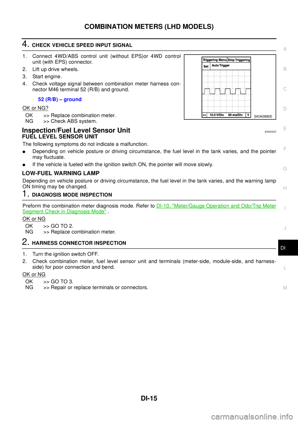
4.CHECK VEHICLE SPEED INPUT SIGNAL
1. Connect 4WD/ABS control unit (without EPS)or 4WD control
unit (with EPS) connector.
2. Lift up drive wheels.
3. Start engine.
4. Check voltage signal between combination meter harness con-
nector M46 terminal 52 (R/B) and ground.
OK or NG?
OK >> Replace combination meter.
NG >> Check ABS system.
Inspection/Fuel Level Sensor UnitEKS002ZI
FUEL LEVEL SENSOR UNIT
The following symptoms do not indicate a malfunction.
lDepending on vehicle posture or driving circumstance, the fuel level in the tank varies, and the pointer
may fluctuate.
lIf the vehicle is fueled with the ignition switch ON, the pointer will move slowly.
LOW-FUEL WARNING LAMP
Depending on vehicle posture or driving circumstance, the fuel level in the tank varies, and the warning lamp
ON timing may be changed.
1.DIAGNOSIS MODE INSPECTION
Preform the combination meter diagnosis mode. Refer toDI-10, "
Meter/Gauge Operation and Odo/Trip Meter
Segment Check in Diagnosis Mode".
OK or NG
OK >> GO TO 2.
NG >> Replace combination meter.
2.HARNESS CONNECTOR INSPECTION
1. Turn the ignition switch OFF.
2. Check combination meter, fuel level sensor unit and terminals (meter-side, module-side, and harness-
side) for poor connection and bend.
OK or NG
OK >> GO TO 3.
NG >> Repair or replace terminals or connectors.52 (R/B) – ground
SKIA0990E
Page 1076 of 3066

DI-22
COMBINATION METERS (RHD MODELS)
COMBINATION METERS (RHD MODELS)
PFP:24810
System DescriptionEKS0030H
UNIFIED CONTROL METER
lSpeedometer, odo/trip meter, tachometer, fuel gauge and water temperature gauge are controlled totally
by control unit built-in combination meter.
lDigital meter is adopted for odo/trip meter.*
*The record of the odo meter is kept even if the battery cable is disconnected. The record of the trip meter
is erased when the battery cable is disconnected.
lOdo/trip meter segment can be checked in diagnosis mode.
lMeter/gauge can be checked in diagnosis mode.
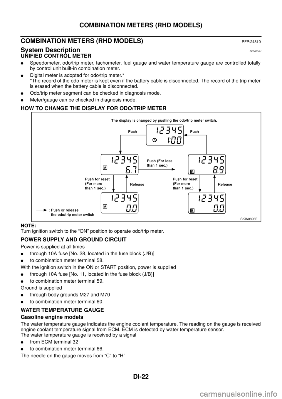
HOW TO CHANGE THE DISPLAY FOR ODO/TRIP METER
NOTE:
Turn ignition switch to the “ON” position to operate odo/trip meter.
POWER SUPPLY AND GROUND CIRCUIT
Power is supplied at all times
lthrough 10A fuse [No. 28, located in the fuse block (J/B)]
lto combination meter terminal 58.
With the ignition switch in the ON or START position, power is supplied
lthrough 10A fuse [No. 11, located in the fuse block (J/B)]
lto combination meter terminal 59.
Ground is supplied
lthrough body grounds M27 and M70
lto combination meter terminal 60.
WATER TEMPERATURE GAUGE
Gasoline engine models
The water temperature gauge indicates the engine coolant temperature. The reading on the gauge is received
engine coolant temperature signal from ECM. ECM is detected by water temperature sensor.
The water temperature gauge is received by a signal
lfrom ECM terminal 32
lto combination meter terminal 66.
The needle on the gauge moves from “C” to “H”
SKIA0896E