Page 2668 of 3066
PB-2
NOISE, VIBRATION, AND HARSHNESS (NVH) TROUBLESHOOTING
NOISE, VIBRATION, AND HARSHNESS (NVH) TROUBLESHOOTING
PFP:00003
NVH Troubleshooting ChartEFS000TJ
Use the chart below to help you find the cause of the symptom. If necessary, repair or replace these parts.
X: ApplicableReference page
Refer to BR section
Refer to BR section.
Refer to BR section
Refer to BR section
—
Refer to BR section
—
—
—
Refer to BR section
Refer to FAX AND RAX section
Refer to FAX AND RAX section
Refer to FSU AND RSU section
Refer to WT section
Refer to WT section
Refer to PS section
Possible cause and
SUSPECTED PARTS
Pads - damaged
Pads - uneven wear
Shims damaged
Rotor imbalance
Rotor damage
Rotor runout
Rotor deformation
Rotor deflection
Rotor rust
Rotor thickness variation
DRIVE SHAFT
AXLE
SUSPENSION
TIRES
ROAD WHEEL
STEERING
Symptom BRAKENoise XXX XXXXXX
Shake X XXXXXX
Shimmy,Judder XXXXXXX XXXXX
Page 2764 of 3066
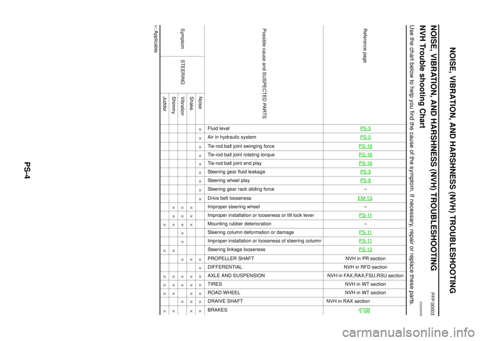
PS-4
NOISE, VIBRATION, AND HARSHNESS (NVH) TROUBLESHOOTING
NOISE, VIBRATION, AND HARSHNESS (NVH) TROUBLESHOOTING
PFP:00003
NVH Trouble shooting ChartEGS000A9
Use the chart below to help you find the cause of the symptom. If necessary, repair or replace these parts.
´: ApplicableReference page
PS-5PS-5PS-16PS-16PS-16PS-5PS-6–
EM-13
.
–
PS-11
–
PS-11PS-11PS-12
NVHinPRsection
NVH in RFD section
NVH in FAX,RAX,FSU,RSU section
NVH in WT section
NVH in WT section
NVH in RAX section
BR-5
.
Possible cause and SUSPECTED PARTS
Fluid level
Air in hydraulic system
Tie-rod ball joint swinging force
Tie-rod ball joint rotating torque
Tie-rod ball joint end play
Steering gear fluid leakage
Steering wheel play
Steering gear rack sliding force
Drive belt looseness
Improper steering wheel
Improper installation or looseness or tilt lock lever
Mounting rubber deterioration
Steering column deformation or damage
Improper installation or looseness of steering column
Steering linkage looseness
PROPELLER SHAFT
DIFFERENTIAL
AXLE AND SUSPENSION
TIRES
ROAD WHEEL
DRAIVE SHAFT
BRAKES
Symptom STEERINGNoise´ ´ ´´´´´ ´ ´ ´´´´´´ ´
Shake´´´ ´ ´´´´ ´
Vibration´´´´´ ´ ´´ ´
Shimmy´´´ ´ ´´´ ´
Judder´ ´ ´´´ ´
Page 2798 of 3066
RAX-2
PRECAUTIONS
PRECAUTIONS
PFP:00001
CautionEDS00060
Observe the following precautions when disassembling and servicing drive shaft.
lPerform work in a location which is as dust-free and dirt-free as possible.
lBefore disassembling and servicing, clean the outside of parts.
lThe disassembly and service location must be clean. Care must be taken to prevent parts from becoming
dirty and to prevent the entry of foreign objects.
lDisassembled parts must be carefully reassembled in the correct order. If work is interrupted, a clean
cover must be placed over parts.
lPaper shop cloths must be used. Fabric shop cloths must not be used because of the danger of lint adher-
ing to parts.
lDisassembled parts (except for rubber parts) should be cleaned with kerosene which shall be removed by
blowing with air or wiping with paper shop cloths.
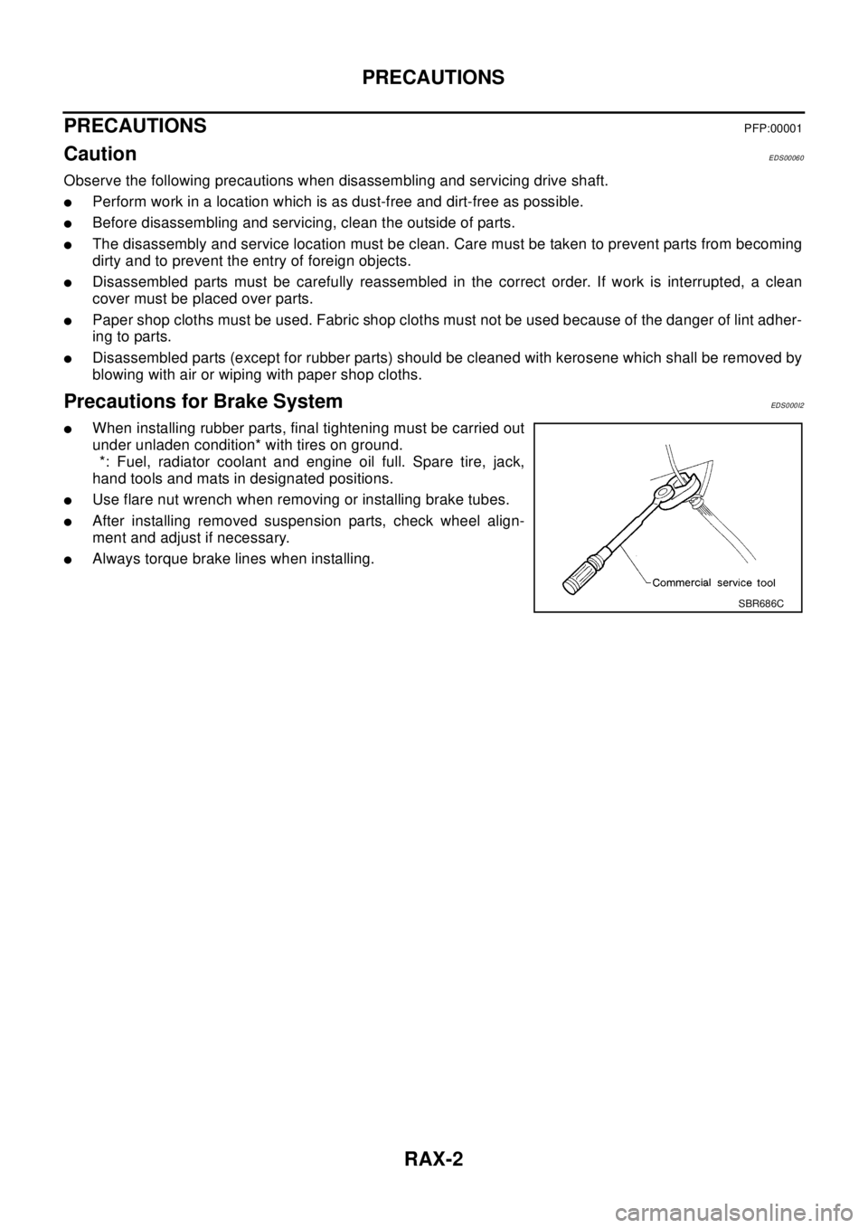
Precautions for Brake SystemEDS0 00 I2
lWhen installing rubber parts, final tightening must be carried out
under unladen condition* with tires on ground.
*: Fuel, radiator coolant and engine oil full. Spare tire, jack,
hand tools and mats in designated positions.
lUse flare nut wrench when removing or installing brake tubes.
lAfter installing removed suspension parts, check wheel align-
ment and adjust if necessary.
lAlways torque brake lines when installing.
SBR686C
Page 2801 of 3066
NOISE, VIBRATION, AND HARSHNESS (NVH) TROUBLESHOOTING
RAX-5
C
E
F
G
H
I
J
K
L
MA
B
RAX
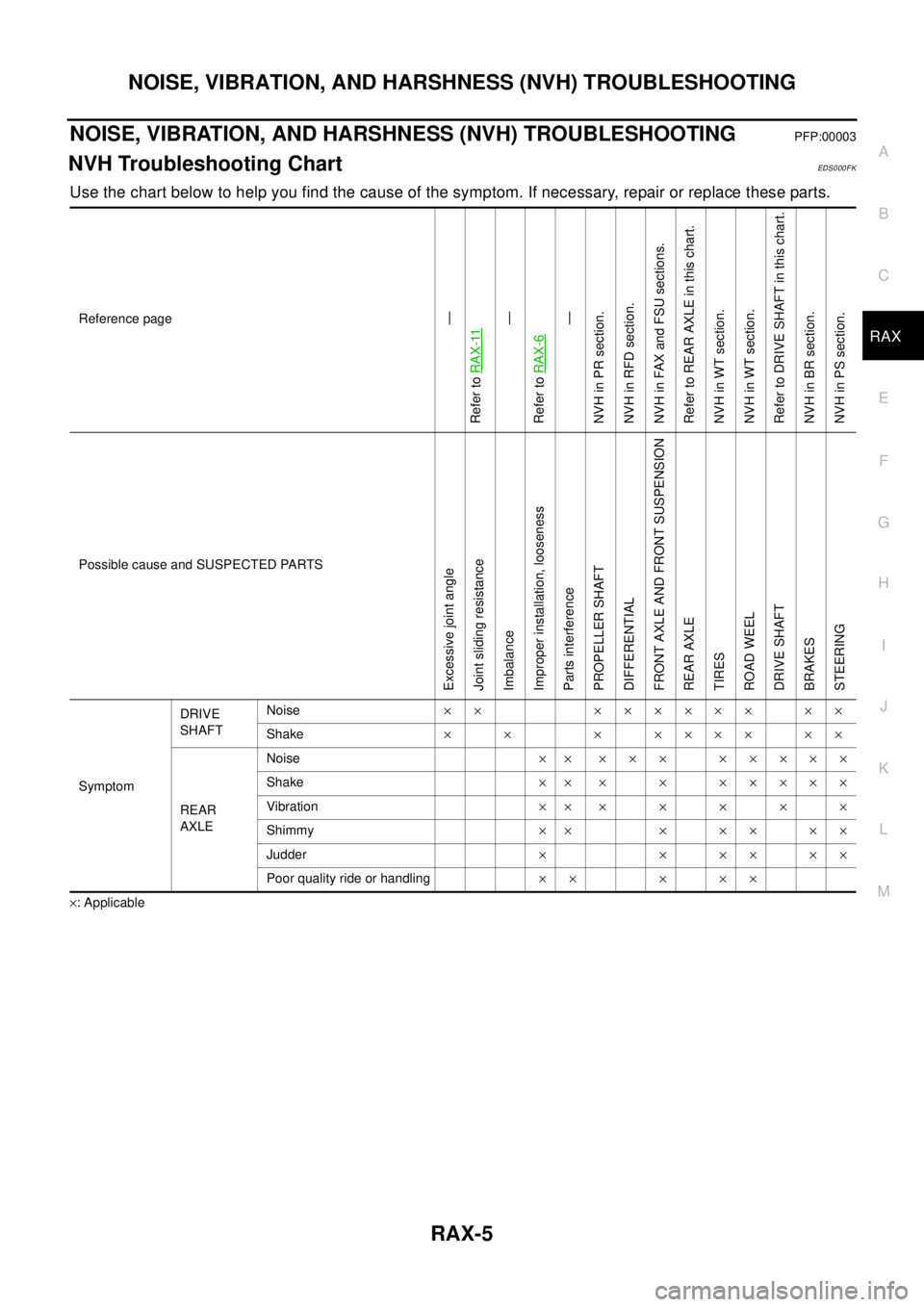
NOISE, VIBRATION, AND HARSHNESS (NVH) TROUBLESHOOTINGPFP:00003
NVH Troubleshooting ChartEDS0 00 F K
Use the chart below to help you find the cause of the symptom. If necessary, repair or replace these parts.
´: ApplicableReference page
—
Refer toRAX-11—
Refer toRAX-6—
NVHinPRsection.
NVH in RFD section.
NVHinFAXandFSUsections.
Refer to REAR AXLE in this chart.
NVH in WT section.
NVH in WT section.
Refer to DRIVE SHAFT in this chart.
NVHinBRsection.
NVH in PS section.
Possible cause and SUSPECTED PARTS
Excessive joint angle
Joint sliding resistance
Imbalance
Improper installation, looseness
Parts interference
PROPELLER SHAFT
DIFFERENTIAL
FRONT AXLE AND FRONT SUSPENSION
REAR AXLE
TIRES
ROAD WEEL
DRIVE SHAFT
BRAKES
STEERING
SymptomDRIVE
SHAFTNoise´´ ´´´´´´ ´´
Shake´´ ´´´´´´´
REAR
AXLENoise´´ ´´´ ´´´´´
Shake´´ ´ ´ ´´´´´
Vibration´´´´´´´
Shimmy´´ ´´´´´
Judder´ ´ ´´ ´´
Poor quality ride or handling´´ ´ ´´
Page 2824 of 3066
RFD-2
PRECAUTIONS
PRECAUTIONS
PFP:00001
CautionEDS00056
lBefore starting diagnosis of the vehicle, understand symptoms well. Perform correct and systematic oper-
ations.
lCheck for the correct installation status prior to removal or disassembly. When mating marks are required,
be sure they do not interfere with the function of the parts they are applied to.
lCarry out an overhaul in a clean work place. Using a dust proof room is recommended.
lBefore disassembly, using steam or white gasoline, completely remove sand and mud from the exterior of
the unit, preventing them from entering into the unit during disassembly or assembly.
lCheck appearance of the disassembled parts for damage, deformation, and abnormal wear. If a malfunc-
tion is detected, replace it with a new one.
lNormally replace lock pins, oil seals, and bearings with new ones every time they are removed.
lIn principle, tighten bolts or nuts gradually in several steps working diagonally from inside to outside. If
tightening sequence is specified, observe it.
lClean and flush the parts sufficiently and blow them dry.
lBe careful not to damage the sliding surfaces and mating surfaces.
lWhen applying sealant, remove the old sealant from the mounting surface; then remove any moisture, oil,
and foreign materials from the application and mounting surfaces.
lAlways use shop paper for cleaning the inside of components.
lAvoid using cotton gloves or a shop cloth to prevent entering of lint.
lDuring assembly, observe the specified tightening torque, and apply new differential oil, Vaseline, or Nis-
san MP Special Grease No. 2, as specified for each vehicle, when necessary.
lDo not reuse drained oil. Discard waste oil after oil changes or part treatment in accordance with local
laws and regulations.
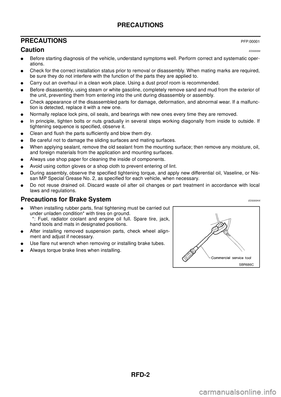
Precautions for Brake SystemEDS000HX
lWhen installing rubber parts, final tightening must be carried out
under unladen condition* with tires on ground.
*: Fuel, radiator coolant and engine oil full. Spare tire, jack,
hand tools and mats in designated positions.
lAfter installing removed suspension parts, check wheel align-
ment and adjust if necessary.
lUse flare nut wrench when removing or installing brake tubes.
lAlways torque brake lines when installing.
SBR686C
Page 2854 of 3066
RSU-2
PRECAUTIONS
PRECAUTIONS
PFP:00001
CautionEES0007C
lFinal tightening of bushings must be carried out under unladen condition with tires on the ground. Oil will
shorten life of bushings. Be sure to wipe off any spilled oil.
l“Unladen condition” means that fuel, coolant and lubricant are full and ready for drive. However, spare tire,
jack, and hand tools should be unloaded.
lAfter installing the removed suspension parts, always check wheel alignment and adjust if necessary.
lReplace the caulking nut with a new one. Install a new nut without wiping the oil off before tightening.
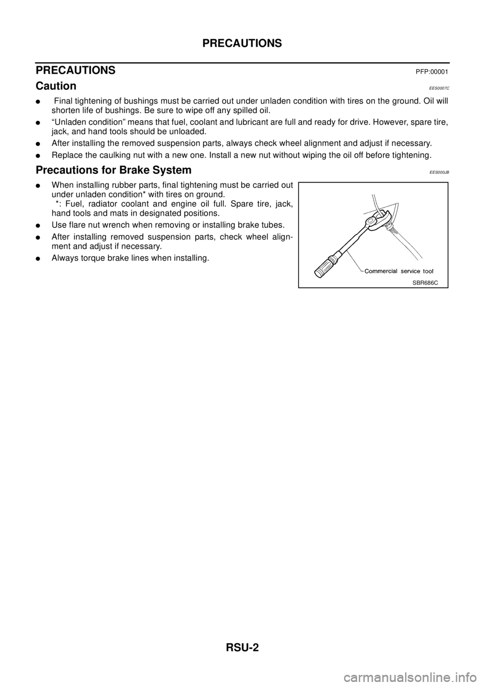
Precautions for Brake SystemEES000JB
lWhen installing rubber parts, final tightening must be carried out
under unladen condition* with tires on ground.
*: Fuel, radiator coolant and engine oil full. Spare tire, jack,
hand tools and mats in designated positions.
lUse flare nut wrench when removing or installing brake tubes.
lAfter installing removed suspension parts, check wheel align-
ment and adjust if necessary.
lAlways torque brake lines when installing.
SBR686C
Page 2856 of 3066
RSU-4
NOISE, VIBRATION, AND HARSHNESS (NVH) TROUBLESHOOTING
NOISE, VIBRATION, AND HARSHNESS (NVH) TROUBLESHOOTING
PFP:00003
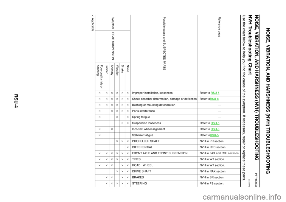
NVH Troubleshooting ChartEES000IE
Use the chart below to help you find the cause of the symptom. If necessary, repair or replace these parts.
´: ApplicableReference page
Refer toRSU-5Refer toRSU-8
—
—
—
Refer toRSU-5
Refer toRSU-6Refer toRSU-5NVHinPRsection.
NVH in RFD section.
NVH in FAX and FSU sections.
NVH in WT section.
NVH in WT section.
NVH in RAX section.
NVHinBRsection.
NVH in PS section.
Possible cause and SUSPECTED PARTS
Improper installation, looseness
Shock absorber deformation, damage or deflection
Bushing or mounting deterioration
Parts interference
Spring fatigue
Suspension looseness
Incorrect wheel alignment
Stabilizer fatigue
PROPELLER SHAFT
DIFFERENTIAL
FRONT AXLE AND FRONT SUSPENSION
TIRES
ROAD WHEEL
DRIVE SHAFT
BRAKES
STEERING
Symptom REAR SUSPENSIONNoise´´´´´´ ´´´´´´´´
Shake´´´´ ´ ´ ´´´´´´
Vibration´´´´´ ´ ´´ ´ ´
Shimmy´´´´ ´ ´´´ ´´
Judder´´´ ´´´ ´´
Poor quality ride or
handling´´´´´ ´´ ´´´
Page 2858 of 3066
RSU-6
REAR SUSPENSION ASSEMBLY
On-Vehicle Inspection and Service
EES0007F
Check axle and suspension parts for excessive play, wear, and damage.
lMove rear wheels (RH/LH) to check abnormal free play.
lRetighten all nuts and bolts to the specified torque.
lCheck strut for oil leakage and damage.
Wheel AlignmentEES0007G
DESCRIPTION
lMeasure wheel alignment under unladen conditions. “Unladen conditions” means that fuel, coolant, and
lubricant are full. However, spare tire, jack, and hand tools should be unloaded.
PRELIMINARY INSPECTION
1. Check the tires for improper air pressure and wear.
2. Check road wheels for runout.
3. Check wheel bearing axial endplay.
4. Check strut operation.
5. Check each mounting point of axle and suspension for looseness and deformation.
6. Check each link and arm for cracks, deformation, and other damage.
7. Check the vehicle posture.
CAMBER
Camber is preset at factory and cannot be adjusted.
lIf the camber is not within specification, inspect and replace any damaged or worn rear suspension parts.
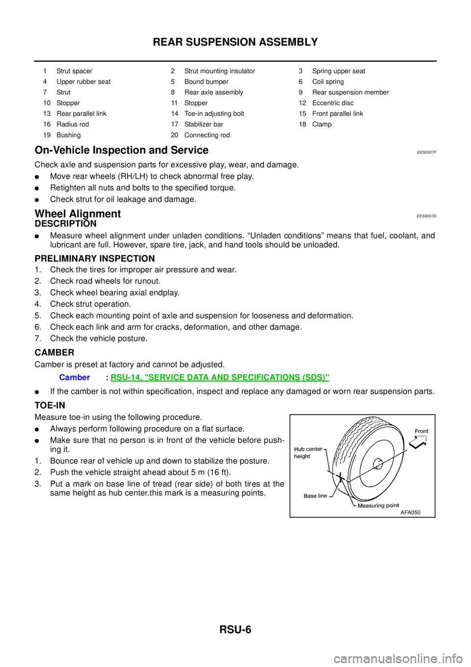
TOE-IN
Measure toe-in using the following procedure.
lAlways perform following procedure on a flat surface.
lMake sure that no person is in front of the vehicle before push-
ing it.
1. Bounce rear of vehicle up and down to stabilize the posture.
2. Push the vehicle straight ahead about 5 m (16 ft).
3. Put a mark on base line of tread (rear side) of both tires at the
same height as hub center.this mark is a measuring points.
1 Strut spacer 2 Strut mounting insulator 3 Spring upper seat
4 Upper rubber seat 5 Bound bumper 6 Coil spring
7 Strut 8 Rear axle assembly 9 Rear suspension member
10 Stopper 11 Stopper 12 Eccentric disc
13 Rear parallel link 14 Toe-in adjusting bolt 15 Front parallel link
16 Radius rod 17 Stabilizer bar 18 Clamp
19 Bushing 20 Connecting rod
Camber :RSU-14, "SERVICE DATA AND SPECIFICATIONS (SDS)"
AFA050