Page 2859 of 3066
REAR SUSPENSION ASSEMBLY
RSU-7
C
D
F
G
H
I
J
K
L
MA
B
RSU
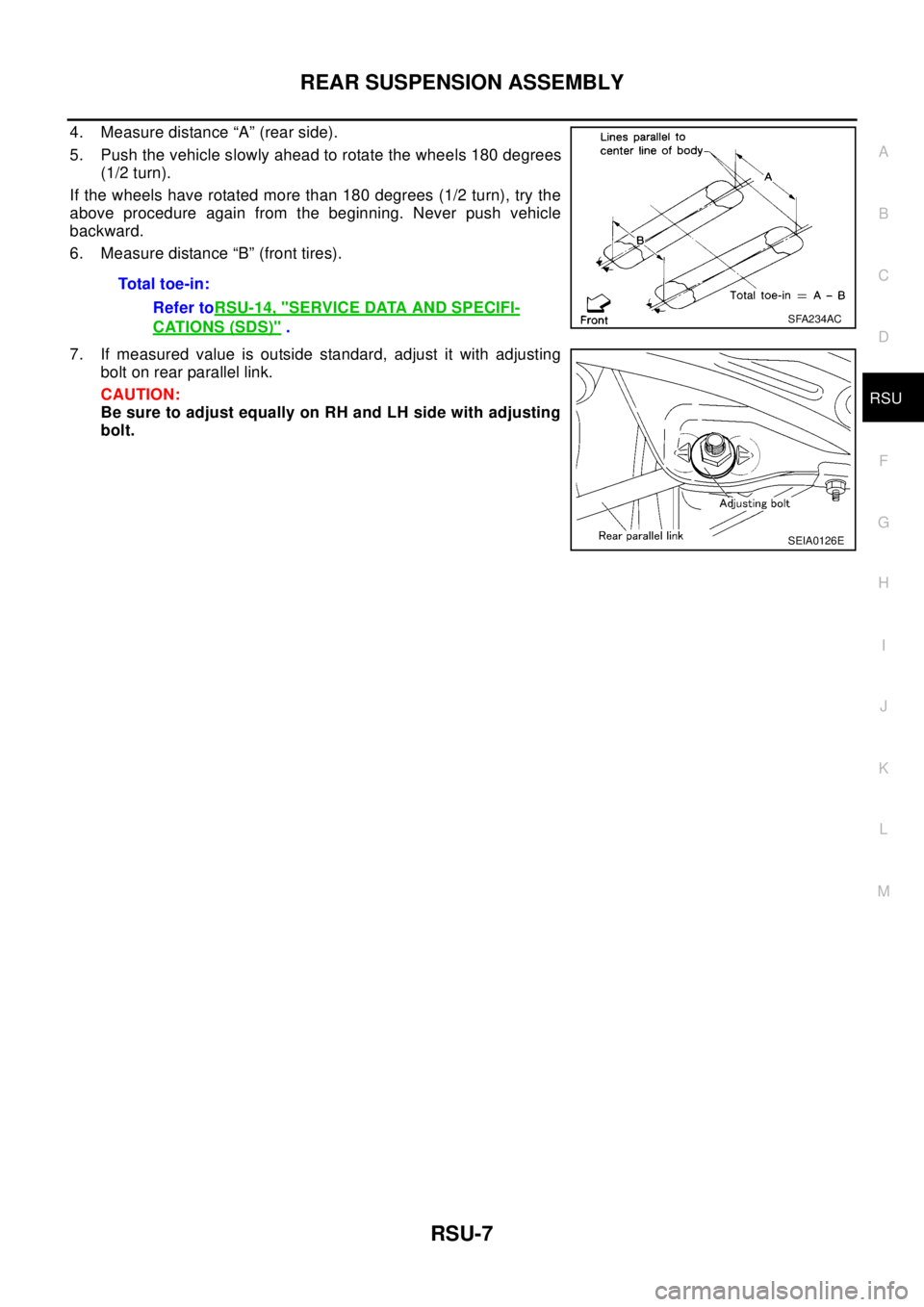
4. Measure distance “A” (rear side).
5. Push the vehicle slowly ahead to rotate the wheels 180 degrees
(1/2 turn).
If the wheels have rotated more than 180 degrees (1/2 turn), try the
above procedure again from the beginning. Never push vehicle
backward.
6. Measure distance “B” (front tires).
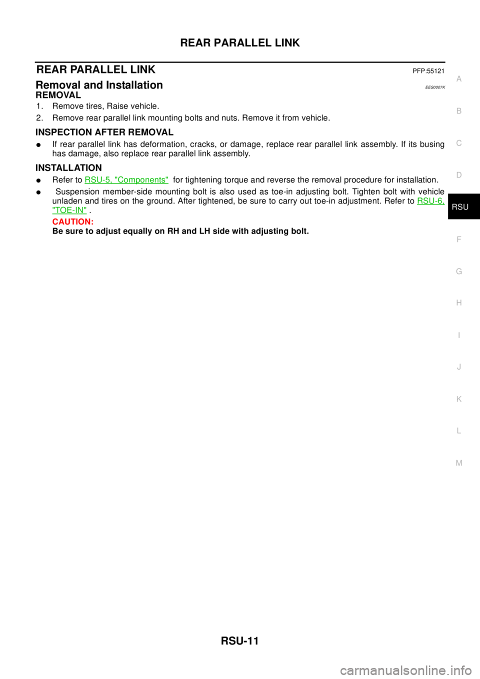
7. If measured value is outside standard, adjust it with adjusting
bolt on rear parallel link.
CAUTION:
Be sure to adjust equally on RH and LH side with adjusting
bolt.Total toe-in:
Refer toRSU-14, "
SERVICE DATA AND SPECIFI-
CATIONS (SDS)".SFA234AC
SEIA0126E
Page 2860 of 3066
RSU-8
COIL SPRING AND STRUT
COIL SPRING AND STRUT
PFP:55302
Removal and InstallationEES0007H
REMOVAL
1. Remove tires.
2. Remove brake hose lock plate and remove brake hose from strut.
3. Remove mounting nuts and washers on upper portion of stabilizer connecting rod.
4. Remove strut-to-axle housing mounting bolts and nuts.
5. Remove luggage side lower finisher in luggage compartment.Remove mounting nuts on upper portion of
strut. Then remove strut from vehicle.
INSTALLATION
lRefer toRSU-5, "Components"for tightening torque. Install in the reverse order of removal.
Disassembly and AssemblyEES0007I
DISASSEMBLY
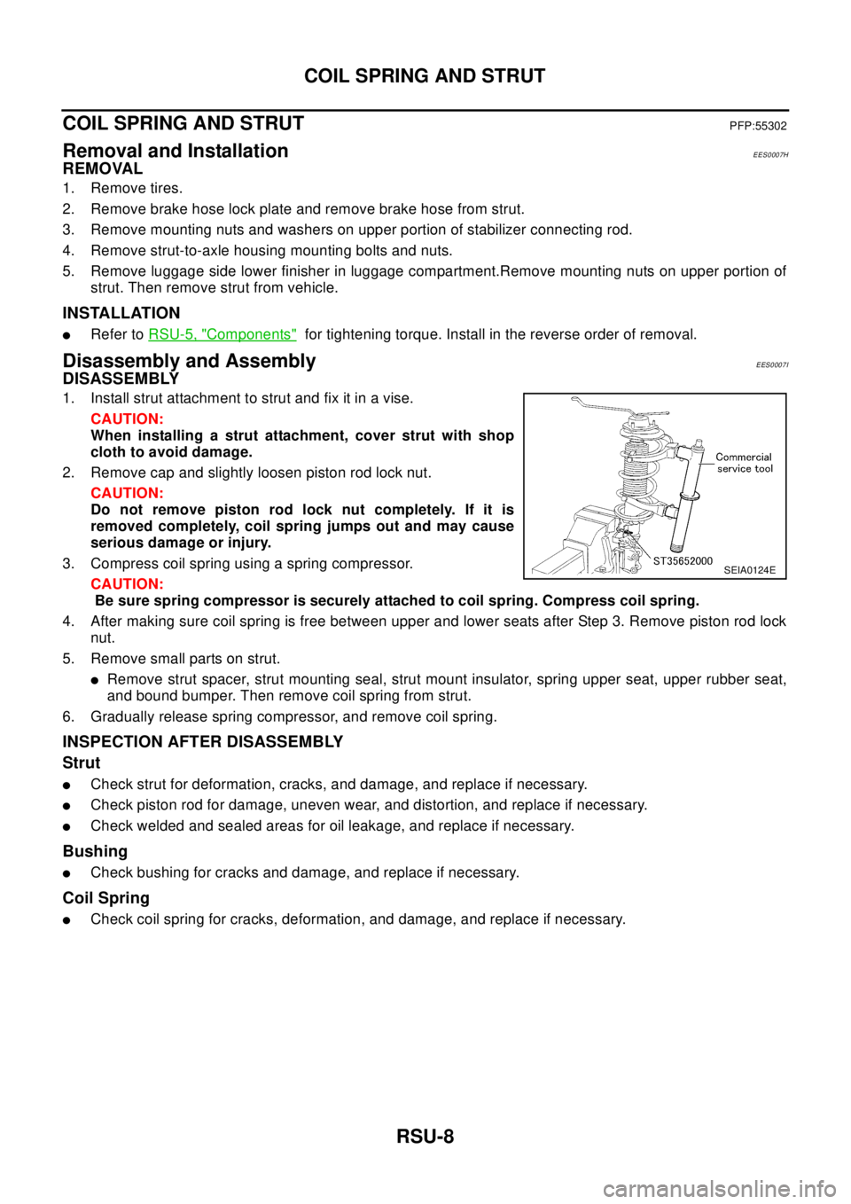
1. Install strut attachment to strut and fix it in a vise.
CAUTION:
When installing a strut attachment, cover strut with shop
cloth to avoid damage.
2. Remove cap and slightly loosen piston rod lock nut.
CAUTION:
Do not remove piston rod lock nut completely. If it is
removed completely, coil spring jumps out and may cause
serious damage or injury.
3. Compress coil spring using a spring compressor.
CAUTION:
Be sure spring compressor is securely attached to coil spring. Compress coil spring.
4. After making sure coil spring is free between upper and lower seats after Step 3. Remove piston rod lock
nut.
5. Remove small parts on strut.
lRemove strut spacer, strut mounting seal, strut mount insulator, spring upper seat, upper rubber seat,
and bound bumper. Then remove coil spring from strut.
6. Gradually release spring compressor, and remove coil spring.
INSPECTION AFTER DISASSEMBLY
Strut
lCheck strut for deformation, cracks, and damage, and replace if necessary.
lCheck piston rod for damage, uneven wear, and distortion, and replace if necessary.
lCheck welded and sealed areas for oil leakage, and replace if necessary.
Bushing
lCheck bushing for cracks and damage, and replace if necessary.
Coil Spring
lCheck coil spring for cracks, deformation, and damage, and replace if necessary.
SEIA0124E
Page 2862 of 3066
RSU-10
FRONT PARALLEL LINK
FRONT PARALLEL LINK
PFP:55120
Removal and InstallationEES0007J
REMOVAL
1. Remove tires, Raise vehicle.
2. Remove ABS wheel speed sensor wire (With ABS models).
3. Remove front parallel link mounting bolts and nuts. Remove front parallel link from vehicle.
INSPECTION AFTER REMOVAL
lReplace front parallel link assembly if it is in following condition: deformed, cracked, or damaged, or if the
bushing was damaged.
INSTALLATION
lRefer toRSU-5, "Components"for tightening torque and reverse the removal procedure for installation.
Page 2863 of 3066
REAR PARALLEL LINK
RSU-11
C
D
F
G
H
I
J
K
L
MA
B
RSU
REAR PARALLEL LINKPFP:55121
Removal and InstallationEES0007K
REMOVAL
1. Remove tires, Raise vehicle.
2. Remove rear parallel link mounting bolts and nuts. Remove it from vehicle.
INSPECTION AFTER REMOVAL
lIf rear parallel link has deformation, cracks, or damage, replace rear parallel link assembly. If its busing
has damage, also replace rear parallel link assembly.
INSTALLATION
lRefer toRSU-5, "Components"for tightening torque and reverse the removal procedure for installation.
lSuspension member-side mounting bolt is also used as toe-in adjusting bolt. Tighten bolt with vehicle
unladen and tires on the ground. After tightened, be sure to carry out toe-in adjustment. Refer toRSU-6,
"TOE-IN".
CAUTION:
Be sure to adjust equally on RH and LH side with adjusting bolt.
Page 2864 of 3066
RSU-12
RADIUS ROD
RADIUS ROD
PFP:55110
Removal and InstallationEES0007L
REMOVAL
1. Remove tires, Raise vehicle.
2. Remove radius rod mounting bolts and nuts and remove radius rod from vehicle.
INSPECTION AFTER REMOVAL
lCheck radius rod and busing for deformation, cracks, and damage, and replace if necessary.
INSTALLATION
lRefer toRSU-5, "Components"for tightening torque and reverse the removal procedure for installation.
Page 2865 of 3066
REAR SUSPENSION MEMBER
RSU-13
C
D
F
G
H
I
J
K
L
MA
B
RSU
REAR SUSPENSION MEMBERPFP:55501
Removal and InstallationEES0007M
REMOVAL
1. Remove tires. Raise vehicle.
2. Remove cotter pin.Remove wheel hub lock nut by using a wheel hub lock nut wrench.
3. Remove ABS wheel speed sensor and wiring (With ABS models).
4. Remove brake caliper and brake hose lock plate, and hang them aside.
5. Remove mounting bolts and nuts on lower portion of strut.
6. Remove axle-side mounting bolts of parallel link and remove rear drive shaft from axle housing.
7. Remove suspension member-side mounting bolt of parallel link and remove parallel link from suspension
member.
8. Remove mounting bolts and nuts on lower portion of strut.
CAUTION:
After removing drive shaft, position axle housing onto strut.
9. Remove propeller shaft.
10. Remove rear exhaust tube.
11. Remove electronically controlled coupling connector and air breather hose from final drive.
12. Set a transmission jack under rear final drive.
13. Remove front and rear mounting bolts from rear final drive.
14. Remove rear final drive from suspension member.
15. Place transmission jack onto rear suspension member. Remove rear suspension member mounting bolts.
Lower transmission jack slowly to remove rear suspension member from vehicle.
INSTALLATION
lRefer toRSU-5, "Components"for tightening torque. Install in the reverse order of removal.
lAfter installation, perform final tightening of each part under unladen conditions with tires on ground.
Check wheel alignment.RSU-6, "
Wheel Alignment".
Page 3002 of 3066

TF-32
ALL MODE 4X4 SYSTEM
4WD MODE SWITCT
AUTO mode (AUTO indicator lamp ON)
lElectronic control allows optimal distribution of torque to front/rear wheels to match road conditions.
lMakes possible stable driving, with no wheel spin, on snowy roads or other slippery surfaces.
lOn roads which do not require 4WD, it contributes to improved fuel economy by driving in conditions close
to front-wheel drive.
lSensors determine the vehicle's turning condition, and in response tight cornering/braking are controlled
by distributing optimum torque to rear wheels.
NOTE:
lWhen driving in AUTO mode or LOCK mode, if there is a large difference between front and rear wheel
speed which continues for a long time, oil temperature of drive system parts becomes too high and 4WD
warning lamp flashes rapidly. (When 4WD warning lamp flashes, vehicle changes to front-wheel drive
conditions.)
lWhen driving in AUTO mode, 4WD warning lamp may flash slowly if there is a significant difference in
pressure or wear between tires. At this time, vehicle performance is not fully available and cautious driving
is required. (Continues until engine is turned OFF.)
lIf 4WD warning lamp is flashing rapidly, stop vehicle and allow it to idle for some time. Flashing will stop
and AUTO mode will be restored.
lIf the warning lamp flashes slowly during driving but remains OFF after engine is restarted, the system is
normal. If it again flashes slowly after driving for some time, vehicle must be inspected.
lWhen the difference of revolution speed between the front and rear wheel with AUTO mode the shift
switch occasionally changes to LOCK mode automatically. This is not malfunction.
LOCK mode (LOCK indicator lamp and AUTO indicator lamp ON)
lFront/rear wheel torque distribution is fixed, ensuring stable driving when climbing slopes.
lWhen LOCK mode is selected, vehicle will switch automatically to AUTO mode if vehicle speed increases.
If vehicle speed then decreases, the vehicle automatically returns to direct 4-wheel driving conditions.
NOTE:
If there is a significant difference in pressure or wear between tires, full vehicle performance is not available.
Tire conditions are detected, and LOCK mode may be prohibited, or else speeds at which LOCK mode is
enabled may be restricted.
2WD mode (indicator lamps OFF)
Vehicle is in front-wheel drive.
NOTE:
lIf front wheels are slipping in 2WD mode, do not switch to AUTO or LOCK. This can cause difficulties for
the system.
lThe shift switch even if the shift switch is in 2WD mode, the sift switch occasionally automatically change
to 4WD mode depending on the driving condition (For example; Depressing the acceleration firmly). this is
not malfunction. How ever, 4WD mode indicator lamp dose not illuminate.
4WD WARNING LAMP
Turns ON when there is a malfunction in 4WD system. It indicates that fail-safe mode is engaged and vehicle
is in 2WD.
Also turns ON when ignition switch is turned ON, for purpose of bulb check. Turns OFF approximately for 3
seconds after the engine starts if system is normal.
4WD waning lamp indiction
Condition Display 4WD warning lamp
Self-diagnosisWhen self-diagnosis is performed, indicates location of
malfunction by number of flashes.-
Lamp checkTurns ON when engine is started to check for burned-out
lamps.Turns ON when ignition switch
is turned ON. Turns OFF
approximately 3 seconds after
engine start.
4WD system malfunction Turns ON if there is malfunction in 4WD system. ON
Page 3003 of 3066
ALL MODE 4X4 SYSTEM
TF-33
C
E
F
G
H
I
J
K
L
MA
B
TF
FAIL- SAFE FUNCTION
lIf a malfunction occurs in 4WD electrical system, and control unit detects the malfunction, 4WD warning
lamp on gauge turns ON to inform driver of system malfunction.
lWhen 4WD warning lamp is ON, vehicle is in 2WD.
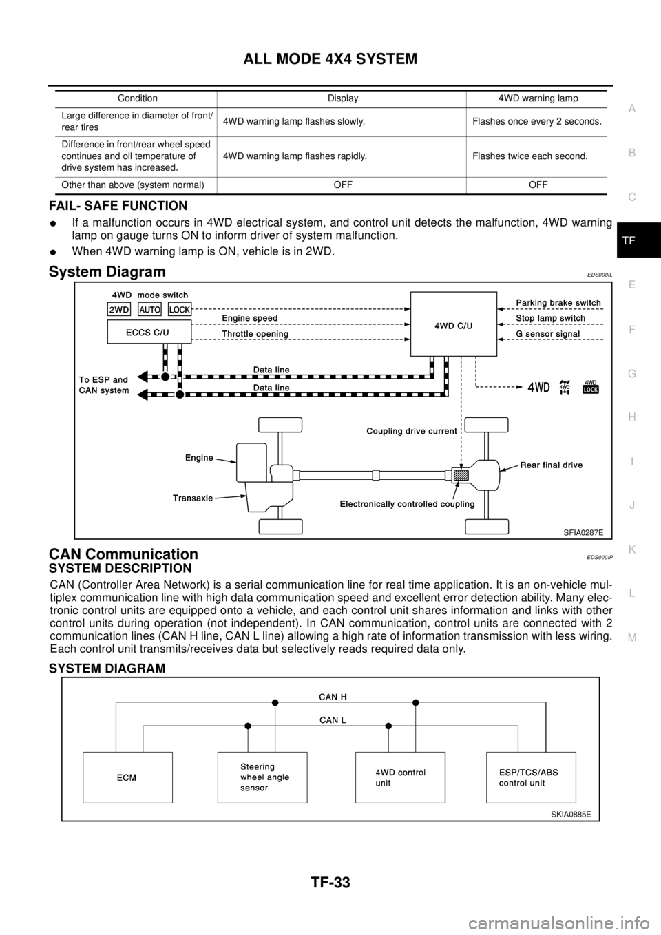
System DiagramEDS000IL
CAN CommunicationEDS000IP
SYSTEM DESCRIPTION
CAN (Controller Area Network) is a serial communication line for real time application. It is an on-vehicle mul-
tiplex communication line with high data communication speed and excellent error detection ability. Many elec-
tronic control units are equipped onto a vehicle, and each control unit shares information and links with other
control units during operation (not independent). In CAN communication, control units are connected with 2
communication lines (CAN H line, CAN L line) allowing a high rate of information transmission with less wiring.
Each control unit transmits/receives data but selectively reads required data only.
SYSTEM DIAGRAM
Largedifferenceindiameteroffront/
rear tires4WD warning lamp flashes slowly. Flashes once every 2 seconds.
Difference in front/rear wheel speed
continues and oil temperature of
drive system has increased.4WD warning lamp flashes rapidly. Flashes twice each second.
Other than above (system normal) OFF OFFCondition Display 4WD warning lamp
SFIA0287E
SKIA0885E