2003 NISSAN X-TRAIL torque
[x] Cancel search: torquePage 25 of 3066
OVERALL SYSTEM
AT-19
D
E
F
G
H
I
J
K
L
MA
B
AT
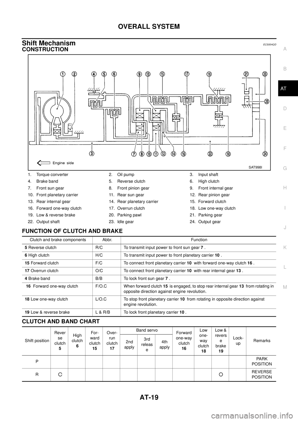
Shift MechanismECS004QD
CONSTRUCTION
FUNCTION OF CLUTCH AND BRAKE
CLUTCH AND BAND CHART
1. Torque converter 2. Oil pump 3. Input shaft
4. Brake band 5. Reverse clutch 6. High clutch
7. Front sun gear 8. Front pinion gear 9. Front internal gear
10. Front planetary carrier 11. Rear sun gear 12. Rear pinion gear
13. Rear internal gear 14. Rear planetary carrier 15. Forward clutch
16. Forward one-way clutch 17. Overrun clutch 18. Low one-way clutch
19. Low & reverse brake 20. Parking pawl 21. Parking gear
22. Output shaft 23. Idle gear 24. Output gear
SAT998I
Clutch and brake components Abbr. Function
5Reverse clutch R/C To transmit input power to front sun gear7.
6High clutch H/C To transmit input power to front planetary carrier10.
15Forward clutch F/C To connect front planetary carrier10with forward one-way clutch16.
17Overrun clutch O/C To connect front planetary carrier10with rear internal gear13.
4Brake band B/B To lock front sun gear7.
16Forward one-way clutch F/O.C When forward clutch15is engaged, to stop rear internal gear13from rotating in
opposite direction against engine revolution.
18Low one-way clutch L/O.C To stop front planetary carrier10from rotating in opposite direction against
engine revolution.
19Low & reverse brake L & R/B To lock front planetary carrier10.
Shift positionRever
se
clutch
5High
clutch
6For-
ward
clutch
15Over-
run
clutch
17Band servo
Forward
one-way
clutch
16Low
one-
way
clutch
18Low &
revers
e
brake
19Lock-
upRemarks
2nd
apply3rd
releas
e4th
apply
PPA R K
POSITION
RREVERSE
POSITION
Page 33 of 3066
OVERALL SYSTEM
AT-27
D
E
F
G
H
I
J
K
L
MA
B
AT
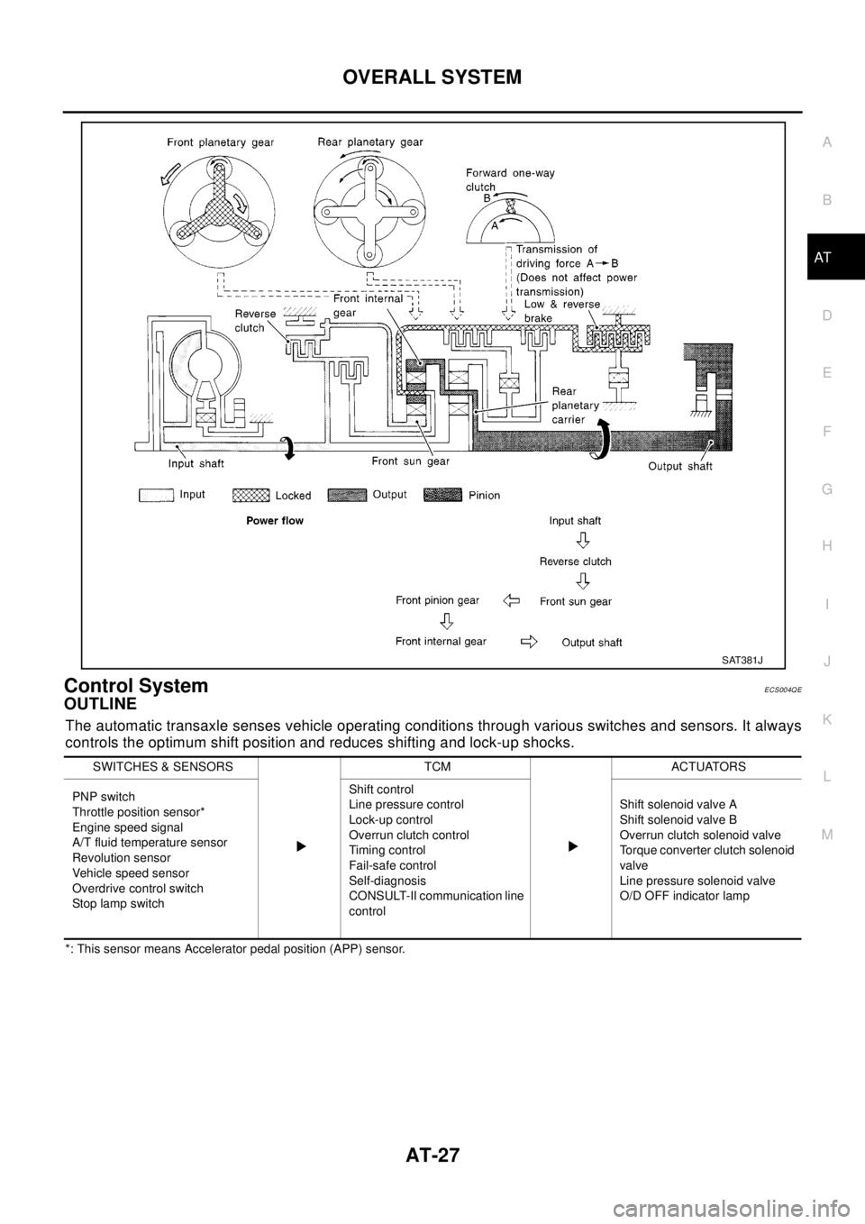
Control SystemECS004QE
OUTLINE
The automatic transaxle senses vehicle operating conditions through various switches and sensors. It always
controls the optimum shift position and reduces shifting and lock-up shocks.
*: This sensor means Accelerator pedal position (APP) sensor.
SAT381J
SWITCHES & SENSORS TCM ACTUATORS
PNP switch
Throttle position sensor*
Engine speed signal
A/T fluid temperature sensor
Revolution sensor
Vehicle speed sensor
Overdrive control switch
Stop la mp s witchShift control
Line pressure control
Lock-up control
Overrunclutchcontrol
Timing control
Fail-safe control
Self-diagnosis
CONSULT-II communication line
controlShift solenoid valve A
Shift solenoid valve B
Overrun clutch solenoid valve
Torque converter clutch solenoid
valve
Line pressure solenoid valve
O/D OFF indicator lamp
Page 35 of 3066
OVERALL SYSTEM
AT-29
D
E
F
G
H
I
J
K
L
MA
B
AT
Control MechanismECS004QF
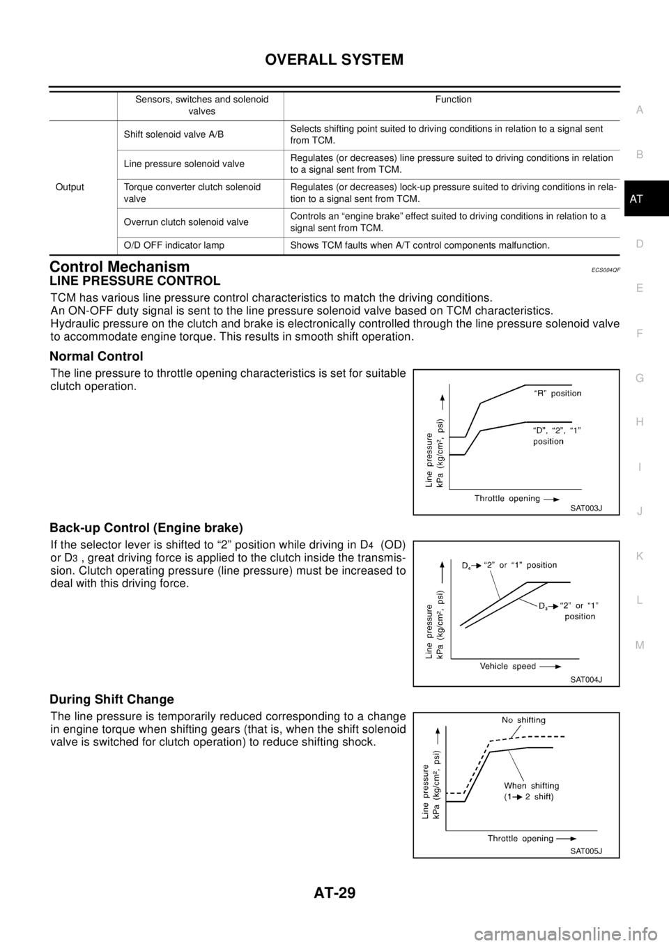
LINE PRESSURE CONTROL
TCM has various line pressure control characteristics to match the driving conditions.
An ON-OFF duty signal is sent to the line pressure solenoid valve based on TCM characteristics.
Hydraulic pressure on the clutch and brake is electronically controlled through the line pressure solenoid valve
to accommodate engine torque. This results in smooth shift operation.
Normal Control
The line pressure to throttle opening characteristics is set for suitable
clutch operation.
Back-up Control (Engine brake)
If the selector lever is shifted to “2” position while driving in D4(OD)
or D
3, great driving force is applied to the clutch inside the transmis-
sion. Clutch operating pressure (line pressure) must be increased to
deal with this driving force.
During Shift Change
The line pressure is temporarily reduced corresponding to a change
in engine torque when shifting gears (that is, when the shift solenoid
valve is switched for clutch operation) to reduce shifting shock.
OutputShift solenoid valve A/BSelects shifting point suited to driving conditions in relation to a signal sent
from TCM.
Line pressure solenoid valveRegulates (or decreases) line pressure suited to driving conditions in relation
to a signal sent from TCM.
Torque converter clutch solenoid
valveRegulates (or decreases) lock-up pressure suited to driving conditions in rela-
tion to a signal sent from TCM.
Overrun clutch solenoid valveControls an “engine brake” effect suited to driving conditions in relation to a
signal sent from TCM.
O/D OFF indicator lamp Shows TCM faults when A/T control components malfunction.Sensors, switches and solenoid
valvesFunction
SAT003J
SAT004J
SAT005J
Page 37 of 3066
OVERALL SYSTEM
AT-31
D
E
F
G
H
I
J
K
L
MA
B
AT
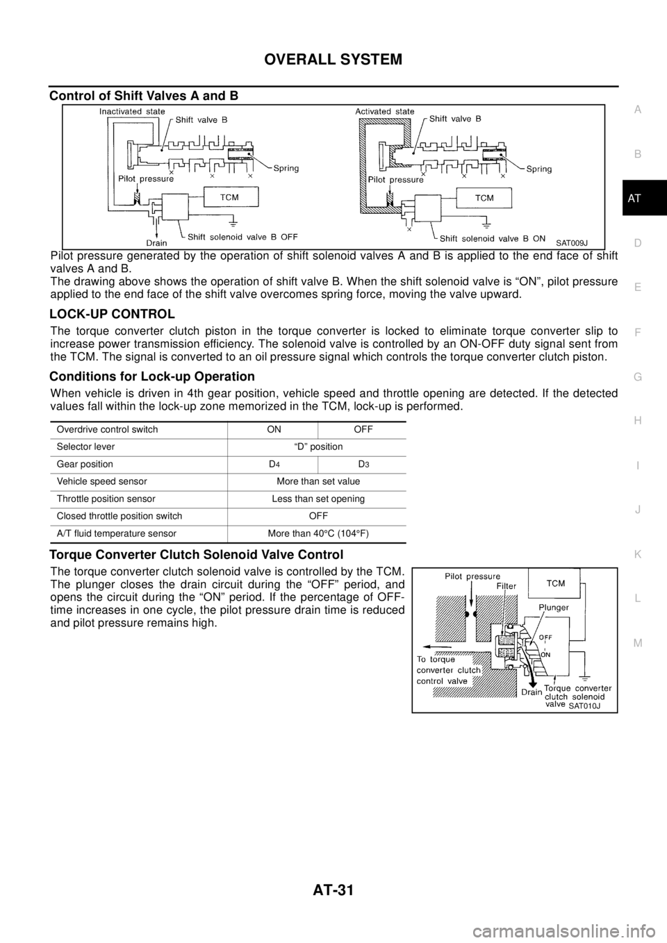
Control of Shift Valves A and B
Pilot pressure generated by the operation of shift solenoid valves A and B is applied to the end face of shift
valves A and B.
The drawing above shows the operation of shift valve B. When the shift solenoid valve is “ON”, pilot pressure
applied to the end face of the shift valve overcomes spring force, moving the valve upward.
LOCK-UP CONTROL
The torque converter clutch piston in the torque converter is locked to eliminate torque converter slip to
increase power transmission efficiency. The solenoid valve is controlled by an ON-OFF duty signal sent from
the TCM. The signal is converted to an oil pressure signal which controls the torque converter clutch piston.
Conditions for Lock-up Operation
When vehicle is driven in 4th gear position, vehicle speed and throttle opening are detected. If the detected
values fall within the lock-up zone memorized in the TCM, lock-up is performed.
Torque Converter Clutch Solenoid Valve Control
The torque converter clutch solenoid valve is controlled by the TCM.
The plunger closes the drain circuit during the “OFF” period, and
opens the circuit during the “ON” period. If the percentage of OFF-
time increases in one cycle, the pilot pressure drain time is reduced
and pilot pressure remains high.
SAT009J
Overdrive control switch ON OFF
Selector lever “D” position
Gear position D
4D3
Vehicle speed sensor More than set value
Throttle position sensor Less than set opening
Closed throttle position switch OFF
A/T fluid temperature sensor More than 40°C(104°F)
SAT010J
Page 38 of 3066
AT-32
OVERALL SYSTEM
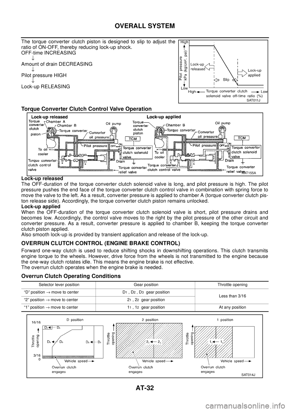
The torque converter clutch piston is designed to slip to adjust the
ratio of ON-OFF, thereby reducing lock-up shock.
OFF-time INCREASING
¯
Amount of drain DECREASING
¯
Pilot pressure HIGH
¯
Lock-up RELEASING
Torque Converter Clutch Control Valve Operation
Lock-up released
The OFF-duration of the torque converter clutch solenoid valve is long, and pilot pressure is high. The pilot
pressure pushes the end face of the torque converter clutch control valve in combination with spring force to
move the valve to the left. As a result, converter pressure is applied to chamber A (torque converter clutch pis-
ton release side). Accordingly, the torque converter clutch piston remains unlocked.
Lock-up applied
When the OFF-duration of the torque converter clutch solenoid valve is short, pilot pressure drains and
becomes low. Accordingly, the control valve moves to the right by the pilot pressure of the other circuit and
converter pressure. As a result, converter pressure is applied to chamber B, keeping the torque converter
clutch piston applied.
Also smooth lock-up is provided by transient application and release of the lock-up.
OVERRUN CLUTCH CONTROL (ENGINE BRAKE CONTROL)
Forward one-way clutch is used to reduce shifting shocks in downshifting operations. This clutch transmits
engine torque to the wheels. However, drive force from the wheels is not transmitted to the engine because
the one-way clutch rotates idle. This means the engine brake is not effective.
The overrun clutch operates when the engine brake is needed.
Overrun Clutch Operating Conditions
SAT011J
AAT155A
Selector lever position Gear position Throttle opening
“D” position®move to center D
1,D2,D3gear position
Less than 3/16
“2” position®move to center 2
1,22gear position
“1” position®move to center 1
1,12gear position At any position
SAT014J
Page 40 of 3066
AT-34
OVERALL SYSTEM
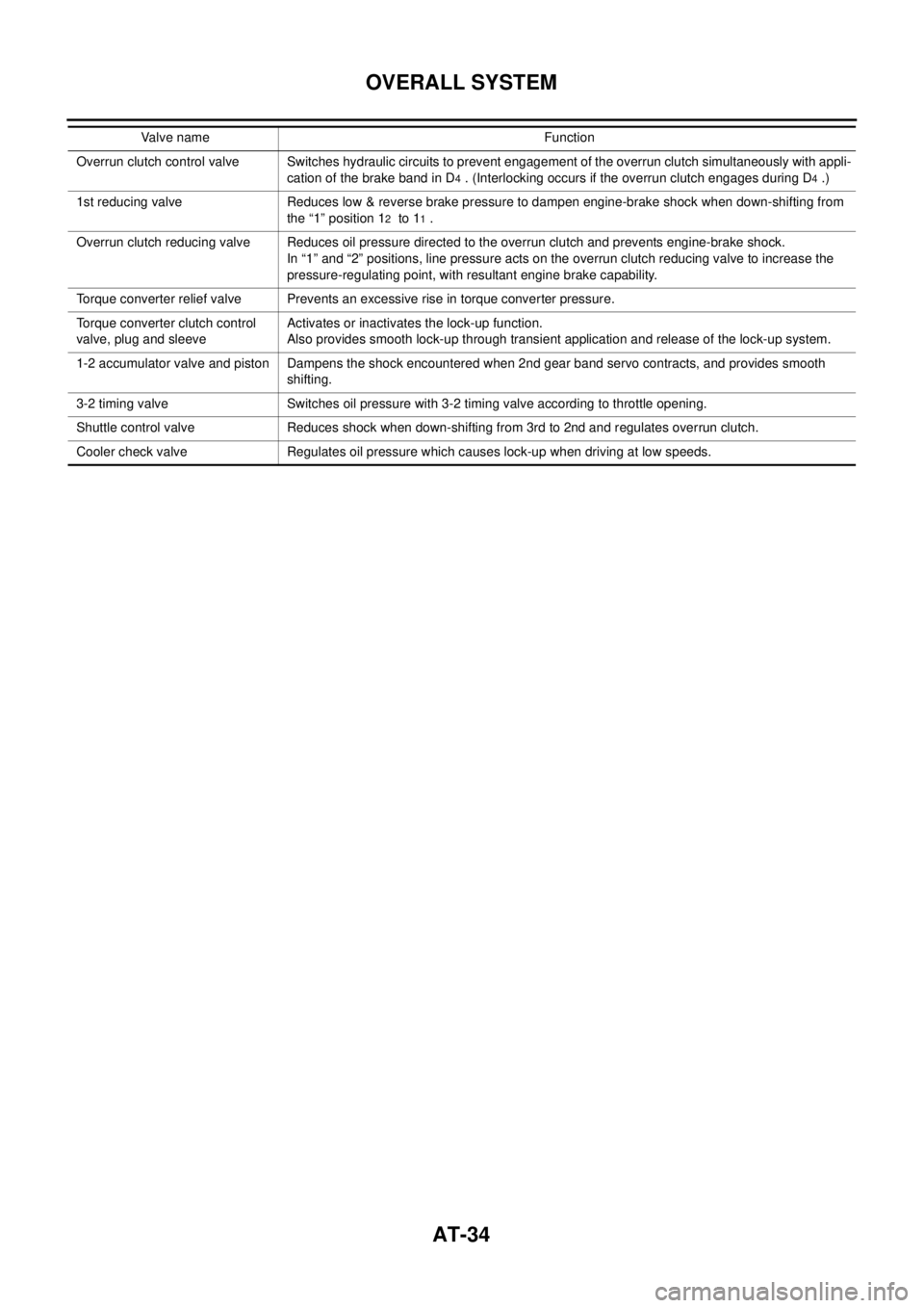
Overrun clutch control valve Switches hydraulic circuits to prevent engagement of the overrun clutch simultaneously with appli-
cation of the brake band in D
4. (Interlocking occurs if the overrun clutch engages during D4.)
1st reducing valve Reduces low & reverse brake pressure to dampen engine-brake shock when down-shifting from
the “1” position 1
2to 11.
Overrun clutch reducing valve Reduces oil pressure directed to the overrun clutch and prevents engine-brake shock.
In “1” and “2” positions, line pressure acts on the overrun clutch reducing valve to increase the
pressure-regulating point, with resultant engine brake capability.
Torque converter relief valve Prevents an excessive rise in torque converter pressure.
Torque converter clutch control
valve, plug and sleeveActivates or inactivates the lock-up function.
Also provides smooth lock-up through transient application and release of the lock-up system.
1-2 accumulator valve and piston Dampens the shock encountered when 2nd gear band servo contracts, and provides smooth
shifting.
3-2 timing valve Switches oil pressure with 3-2 timing valve according to throttle opening.
Shuttle control valve Reduces shock when down-shifting from 3rd to 2nd and regulates overrun clutch.
Cooler check valve Regulates oil pressure which causes lock-up when driving at low speeds.Valve name Function
Page 41 of 3066

TROUBLE DIAGNOSIS — INDEX
AT-35
[EURO-OBD]
D
E
F
G
H
I
J
K
L
MA
B
AT
[EURO-OBD]TROUBLE DIAGNOSIS — INDEXPFP:00000
Alphabetical & P No. Index for DTCECS003VK
ALPHABETICAL INDEX FOR DTC
Check if the vehicle is a model with Euro-OBD system or not by the “Type approval number” on the identifica-
tion plate. Refer toGI-45, "
IDENTIFICATION PLATE".
l*1: These numbers are prescribed by SAE J2012.
l*2: When the fail-safe operation occurs, the MIL illuminates.
l*3: The MIL illuminates when both the “Revolution sensor signal” and the “Vehicle speed sensor signal” meet the fail-safe condition at
thesametime.Type approval number Model
Available With Euro-OBD system
Not available (blank) Without Euro-OBD system
Items
(CONSULT-II screen terms)DTC
Reference page
CONSULT-II
GST*1
A/T 1ST GR FNCTN P0731AT- 1 5 1 , "
DTC P0731 A/T 1ST
GEAR FUNCTION"
A/T 2ND GR FNCTN P0732AT- 1 5 8 , "DTC P0732 A/T 2ND
GEAR FUNCTION"
A/T 3RD GR FNCTN P0733AT- 1 6 5 , "DTC P0733 A/T 3RD
GEAR FUNCTION"
A/T 4TH GR FNCTN P0734AT- 1 7 2 , "DTC P0734 A/T 4TH
GEAR FUNCTION"
ATF TEMP SEN/CIRC P0710AT- 1 3 6 , "
DTC P0710 A/T FLUID
TEMPERATURE SENSOR
CIRCUIT"
ENGINE SPEED SIG P0725AT- 1 4 7 , "DTC P0725 ENGINE
SPEED SIGNAL"
L/PRESS SOL/CIRC P0745AT-186, "
DTC P0745 LINE
PRESSURE SOLENOID
VA LV E"
O/R CLTCH SOL/CIRC P1760AT- 2 0 8 , "
DTC P1760 OVER-
RUN CLUTCH SOLENOID
VA LV E"
PNP SW/CIRC P0705AT-1 3 0 , "
DTC P0705 PARK/
NEUTRAL POSITION (PNP)
SWITCH"
SFT SOL A/CIRC*2 P0750AT- 1 9 3 , "DTC P0750 SHIFT
SOLENOID VALVE A"
SFT SOL B/CIRC*2 P0755AT- 1 9 8 , "DTC P0755 SHIFT
SOLENOID VALVE B"
TCC SOLENOID/CIRC P0740AT-181, "
DTC P0740 TORQUE
CONVERTER CLUTCH SOLE-
NOID VALVE"
TP SEN/CIRC A/T*2 P1705AT- 2 0 3 , "
DTC P1705 ACCEL-
ERATOR PEDAL POSITION
(APP) SENSOR"
VEH SPD SEN/CIR AT*3 P0720AT-142, "
DTC P0720 VEHICLE
SPEED SENSOR·A/T (REVO-
LUTION SENSOR)"
CAN COMM CIRCUIT U1000EC-114, "DTC U1000 CAN
COMMUNICATION LINE"
Page 42 of 3066

AT-36
[EURO-OBD]
TROUBLE DIAGNOSIS — INDEX
PNO.INDEXFORDTC
Check if the vehicle is a model with Euro-OBD system or not by the “Type approval number” on the identifica-
tion plate. Refer toGI-45, "
IDENTIFICATION PLATE".
l*1: These numbers are prescribed by SAE J2012.
l*2: When the fail-safe operation occurs, the MIL illuminates.
l*3: The MIL illuminates when both the “Revolution sensor signal” and the “Vehicle speed sensor signal” meet the fail-safe condition at
thesametime.Type approval number Model
Available With Euro-OBD system
Not available (blank) Without Euro-OBD system
DTC
Items
(CONSULT-II screen terms)Reference page
CONSULT-II
GST*1
P0705 PNP SW/CIRCAT- 1 3 0 , "
DTC P0705 PARK/
NEUTRAL POSITION (PNP)
SWITCH"
P0710 ATF TEMP SEN/CIRCAT-136, "
DTC P0710 A/T FLUID
TEMPERATURE SENSOR
CIRCUIT"
P0720 VEH SPD SEN/CIR AT*3AT- 1 4 2 , "
DTC P0720 VEHICLE
SPEED SENSOR·A/T (REVO-
LUTION SENSOR)"
P0725 ENGINE SPEED SIGAT- 1 4 7 , "DTC P0725 ENGINE
SPEED SIGNAL"
P0731 A/T 1ST GR FNCTNAT- 1 5 1 , "DTC P0731 A/T 1ST
GEAR FUNCTION"
P0732 A/T 2ND GR FNCTNAT- 1 5 8 , "DTC P0732 A/T 2ND
GEAR FUNCTION"
P0733 A/T 3RD GR FNCTNAT- 1 6 5 , "DTC P0733 A/T 3RD
GEAR FUNCTION"
P0734 A/T 4TH GR FNCTNAT- 1 7 2 , "DTC P0734 A/T 4TH
GEAR FUNCTION"
P0740 TCC SOLENOID/CIRCAT- 1 8 1 , "
DTC P0740 TORQUE
CONVERTER CLUTCH SOLE-
NOID VALVE"
P0745 L/PRESS SOL/CIRCAT-186, "
DTC P0745 LINE
PRESSURE SOLENOID
VA LV E"
P0750 SFT SOL A/CIRC*2AT-193, "DTC P0750 SHIFT
SOLENOID VALVE A"
P0755 SFT SOL B/CIRC*2AT-198, "DTC P0755 SHIFT
SOLENOID VALVE B"
P1705 TP SEN/CIRC A/T*2AT- 2 0 3 , "
DTC P1705 ACCEL-
ERATOR PEDAL POSITION
(APP) SENSOR"
P1760 O/R CLTCH SOL/CIRCAT-208, "
DTC P1760 OVER-
RUNCLUTCHSOLENOID
VA LV E"
U1000 CAN COMM CIRCUITEC-114, "DTC U1000 CAN
COMMUNICATION LINE"