Page 3036 of 3066

WT-4
ROAD WHEEL TIRE ASSEMBLY
ROAD WHEEL TIRE ASSEMBLY
PFP:40300
Balancing Wheels (Bonding Weight Type)EES000J5
REMOVAL
1. Remove inner and outer balance weights from the road wheel.
CAUTION:
Be careful not to scratch the road wheel during removal procedures.
2. Using releasing agent, remove double-faced adhesive tape from the road wheel.
CAUTION:
Be careful not to scratch the road wheel during removal.
lAfter removing double-faced adhesive tape, wipe clean traces of releasing agent from the road wheel.
WHEEL BALANCE ADJUSTMENT
lIf a tire balance machine has adhesion balance weight mode settings and drive-in weight mode setting,
select and adjust a drive-in weight mode suitable for road wheels.
1. Set road wheel on wheel balancer using the center hole as a guide. Start the tire balance machine.
2. When inner and outer unbalance values are shown on the wheel balancer indicator, multiply outer unbal-
ance value by 1.6 to determine balance weight that should be used. Select the outer balance weight with
a value closest to the calculated value above and install it to the designated outer position of, or at the
designated angle in relation to the road wheel.
CAUTION:
lDo not install the inner balance weight before installing the outer balance weight.
lBefore installing the balance weight, be sure to clean the mating surface of the road wheel.
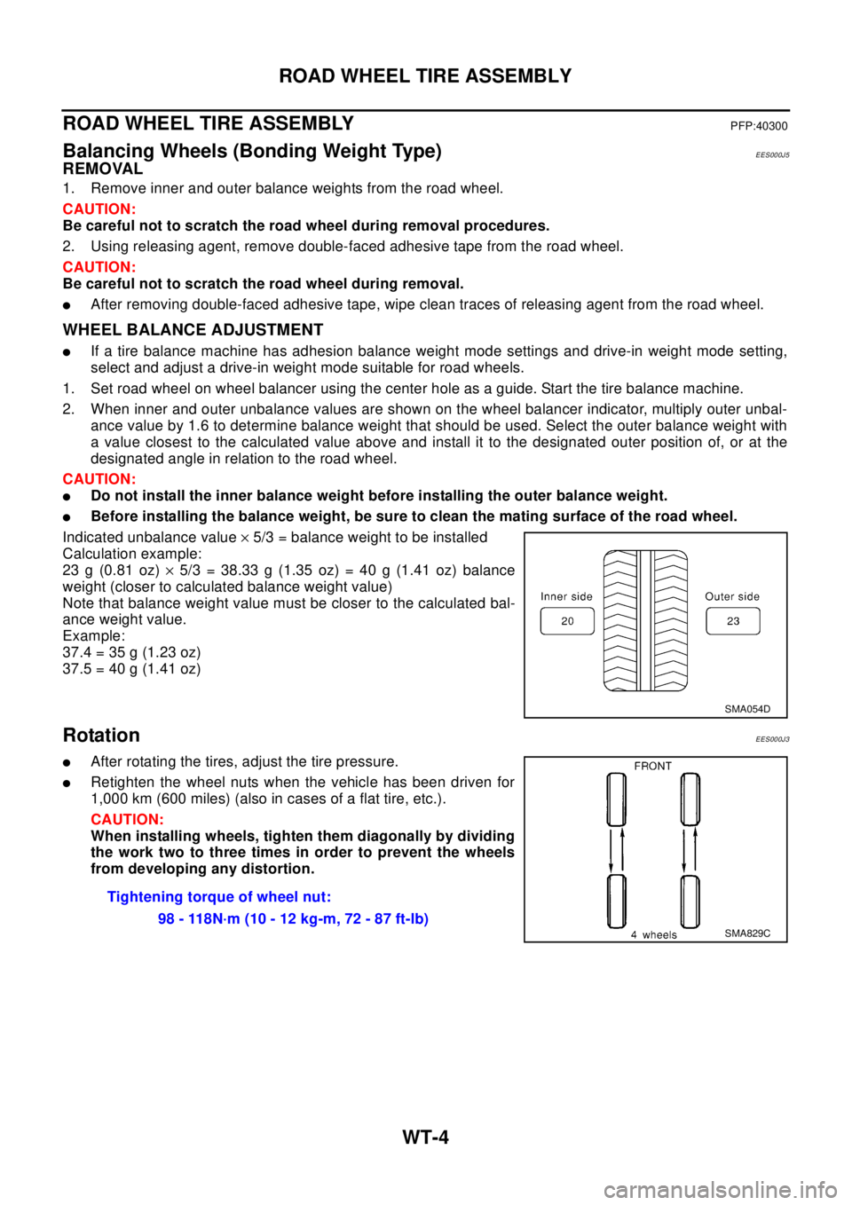
Indicated unbalance value´5/3 = balance weight to be installed
Calculation example:
23 g (0.81 oz)´5/3 = 38.33 g (1.35 oz) = 40 g (1.41 oz) balance
weight (closer to calculated balance weight value)
Note that balance weight value must be closer to the calculated bal-
ance weight value.
Example:
37.4=35g(1.23oz)
37.5=40g(1.41oz)
RotationEES000J3
lAfter rotating the tires, adjust the tire pressure.
lRetighten the wheel nuts when the vehicle has been driven for
1,000 km (600 miles) (also in cases of a flat tire, etc.).
CAUTION:
When installing wheels, tighten them diagonally by dividing
the work two to three times in order to prevent the wheels
from developing any distortion.
SMA054D
Tightening torque of wheel nut:
98 - 118N·m (10 - 12 kg-m, 72 - 87 ft-lb)
SMA829C
Page 3045 of 3066

FRONT WIPER AND WASHER SYSTEM
WW-7
C
D
E
F
G
H
I
J
L
MA
B
WW
Terminal and Reference Values for Combination SwitchEKS0032P
Removal and Installation for Front Wiper Arms, Adjustment for Wiper Arms
Stop Location
EKS0032Q
1. Prior to wiper arm installation, turn on wiper switch to operate
wiper motor and then turn it “OFF” (Auto Stop).
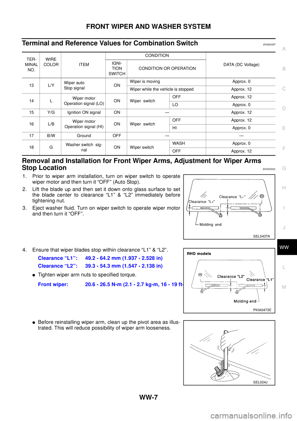
2. Lift the blade up and then set it down onto glass surface to set
the blade center to clearance “L1” & “L2” immediately before
tightening nut.
3. Eject washer fluid. Turn on wiper switch to operate wiper motor
and then turn it “OFF”.
4. Ensure that wiper blades stop within clearance “L1” & “L2”.
lTighten wiper arm nuts to specified torque.
lBefore reinstalling wiper arm, clean up the pivot area as illus-
trated. This will reduce possibility of wiper arm looseness.
TER-
MINAL
NO.WIRE
COLOR ITEMCONDITION
DATA (DC Voltage) IGNI-
TION
SWITCHCONDITION OR OPERATION
13 L/YWiper auto
Stop signalONWiper is moving Approx. 0
Wiper while the vehicle is stopped Approx. 12
14 LWiper motor
Operation signal (LO)ON Wiper switchOFF Approx. 12
LO Approx. 0
15 Y/G Ignition ON signal ON — Approx. 12
16 L/BWiper motor
Operation signal (HI)ON Wiper switchOFF Approx. 12
HI Approx. 0
17 B/W Ground OFF — —
18 GWasher switch sig-
nalON Wiper switchWASH Approx. 0
OFF Approx. 12
SEL543TA
Clearance “L1”: 49.2 - 64.2 mm (1.937 - 2.528 in)
Clearance “L2”: 39.3 - 54.3 mm (1.547 - 2.138 in)
Front wiper: 20.6 - 26.5 N-m (2.1 - 2.7 kg-m, 16 - 19 ft-lb)
PKIA0473E
SEL024J
Page 3053 of 3066

REAR WIPER AND WASHER SYSTEM
WW-15
C
D
E
F
G
H
I
J
L
MA
B
WW
Terminal and Reference Values for Combination SwitchEKS00330
Removal and Installation for Rear Wiper ArmsEKS00331
WIPER ARMS
1. Turn on wiper switch to operate wiper motor and then turn it
“OFF” (Auto Stop).
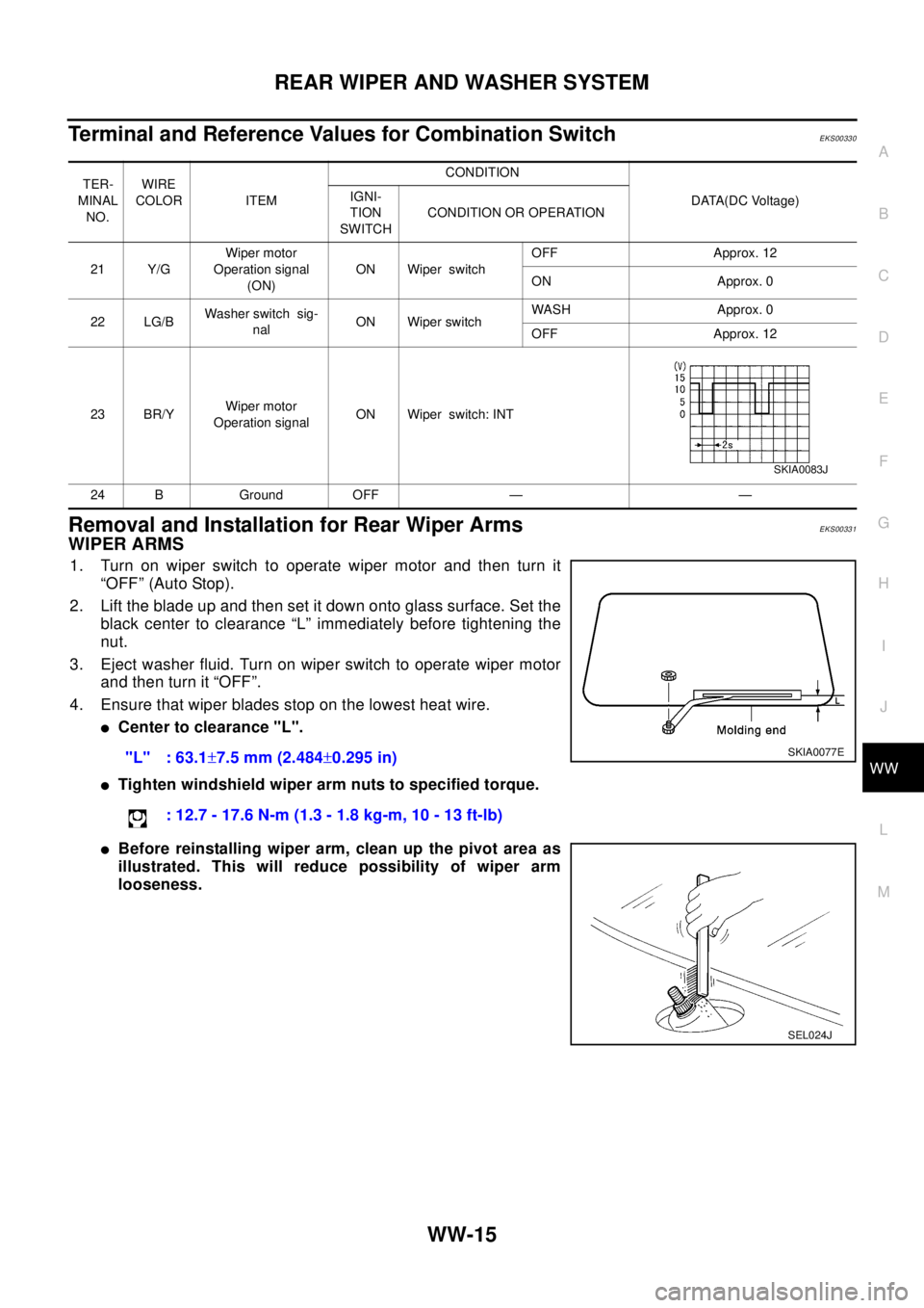
2. Lift the blade up and then set it down onto glass surface. Set the
black center to clearance “L” immediately before tightening the
nut.
3. Eject washer fluid. Turn on wiper switch to operate wiper motor
and then turn it “OFF”.
4. Ensure that wiper blades stop on the lowest heat wire.
lCenter to clearance "L".
lTighten windshield wiper arm nuts to specified torque.
lBefore reinstalling wiper arm, clean up the pivot area as
illustrated. This will reduce possibility of wiper arm
looseness.
TER-
MINAL
NO.WIRE
COLOR ITEMCONDITION
DATA(DC Voltage) IGNI-
TION
SWITCHCONDITION OR OPERATION
21 Y/GWiper motor
Operation signal
(ON)ON Wiper switchOFF Approx. 12
ON Approx. 0
22 LG/BWasher switch sig-
nalON Wiper switchWASH Approx. 0
OFF Approx. 12
23 BR/YWiper motor
Operation signalON Wiper switch: INT
24 B Ground OFF — —
SKIA0083J
"L" : 63.1±7.5 mm (2.484±0.295 in)
: 12.7 - 17.6 N-m (1.3 - 1.8 kg-m, 10 - 13 ft-lb)SKIA0077E
SEL024J
Page 3054 of 3066

WW-16
REAR WIPER AND WASHER SYSTEM
Removal and Installation for Wiper Motor and Linkage
EKS00332
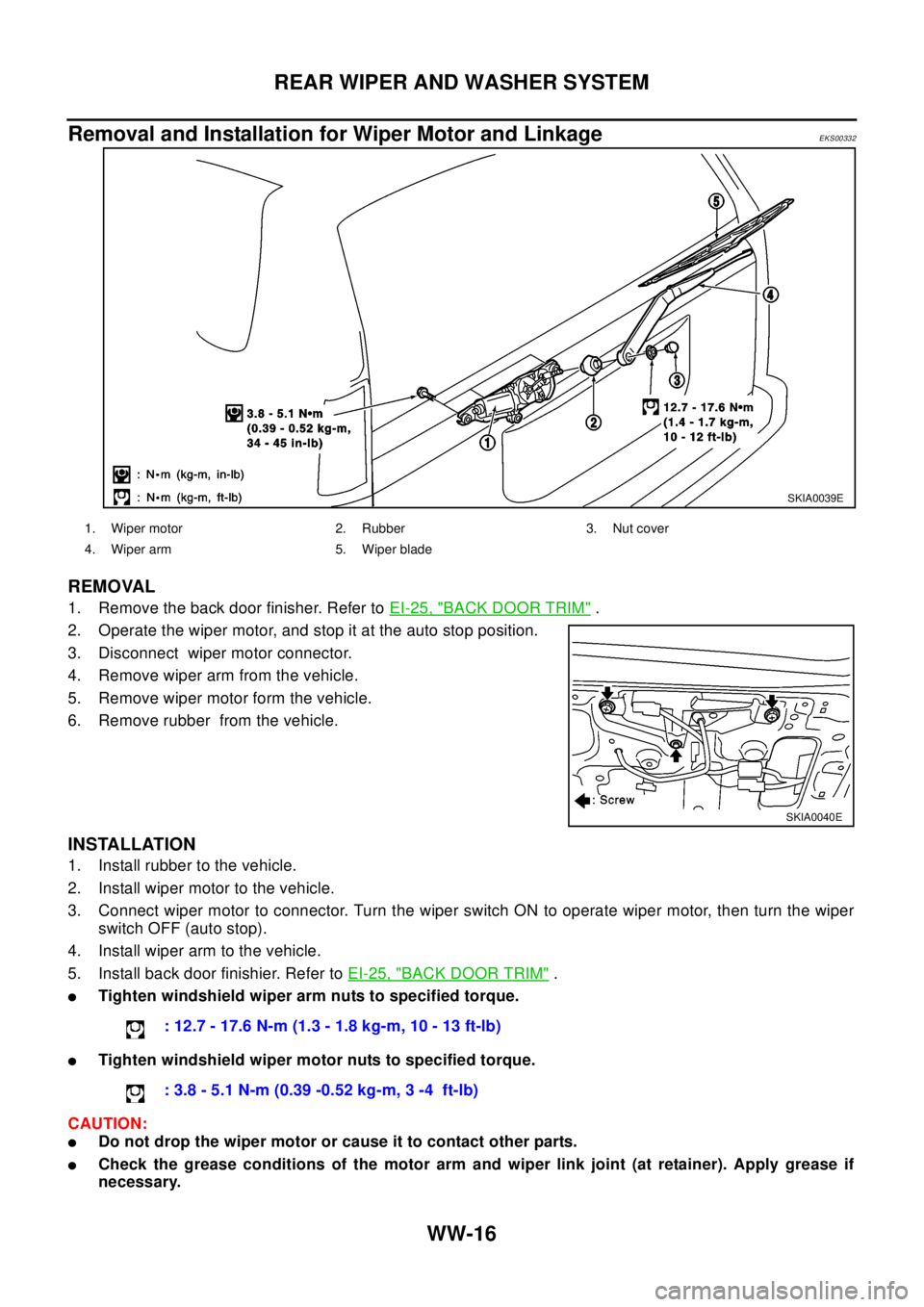
REMOVAL
1. Remove the back door finisher. Refer toEI-25, "BACK DOOR TRIM".
2. Operate the wiper motor, and stop it at the auto stop position.
3. Disconnect wiper motor connector.
4. Remove wiper arm from the vehicle.
5. Remove wiper motor form the vehicle.
6. Remove rubber from the vehicle.
INSTALLATION
1. Install rubber to the vehicle.
2. Install wiper motor to the vehicle.
3. Connect wiper motor to connector. Turn the wiper switch ON to operate wiper motor, then turn the wiper
switch OFF (auto stop).
4. Install wiper arm to the vehicle.
5. Install back door finishier. Refer toEI-25, "
BACK DOOR TRIM".
lTighten windshield wiper arm nuts to specified torque.
lTighten windshield wiper motor nuts to specified torque.
CAUTION:
lDo not drop the wiper motor or cause it to contact other parts.
lCheck the grease conditions of the motor arm and wiper link joint (at retainer). Apply grease if
necessary.
SKIA0039E
1. Wiper motor 2. Rubber 3. Nut cover
4. Wiper arm 5. Wiper blade
SKIA0040E
: 12.7 - 17.6 N-m (1.3 - 1.8 kg-m, 10 - 13 ft-lb)
: 3.8 - 5.1 N-m (0.39 -0.52 kg-m, 3 -4 ft-lb)
Page 3062 of 3066
WW-24
HORN
Removal and Installation
EKS0033B
REMOVAL
1. Remove the front grille.refer toEI-11, "FRONT GRILL"
2. Disconnect horn connector.
3. Remove horn.
INSTALLATION
Tighten horn bolt to specified torque.
SKIA0027E
Horn bolt : 16-18 N·m(1.6-1.8 kg-m, 12-13 ft-lb)