2003 NISSAN X-TRAIL low oil pressure
[x] Cancel search: low oil pressurePage 2796 of 3066

PS-36
SERVICE DATA AND SPECIFICATIONS (SDS)
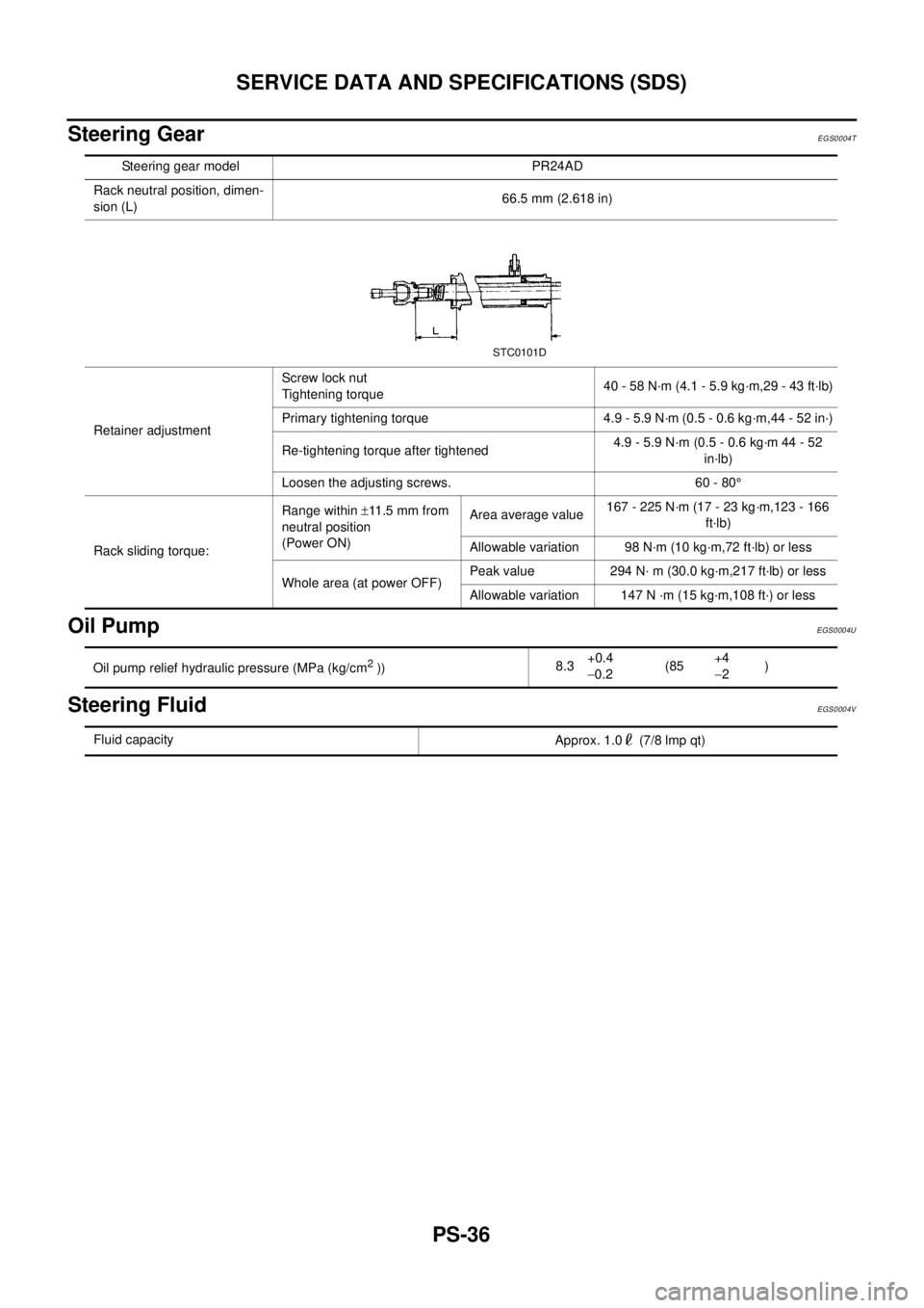
Steering Gear
EGS0004T
Oil PumpEGS0004U
Steering FluidEGS0004V
Steering gear model PR24AD
Rack neutral position, dimen-
sion (L)66.5 mm (2.618 in)
Retainer adjustmentScrew lock nut
Tightening torque40 - 58 N·m (4.1 - 5.9 kg·m,29 - 43 ft·lb)
Primary tightening torque 4.9 - 5.9 N·m (0.5 - 0.6 kg·m,44 - 52 in·)
Re-tightening torque after tightened4.9 - 5.9 N·m (0.5 - 0.6 kg·m 44 - 52
in·lb)
Loosen the adjusting screws. 60 - 80°
Rack sliding torque:Range within±11 .5 m m f r o m
neutral position
(Power ON)Area average value167 - 225 N·m (17 - 23 kg·m,123 - 166
ft·lb)
Allowable variation 98 N·m (10 kg·m,72 ft·lb) or less
Whole area (at power OFF)Peak value 294 N· m (30.0 kg·m,217 ft·lb) or less
Allowable variation 147 N ·m (15 kg·m,108 ft·) or less
STC0101D
Oil pump relief hydraulic pressure (MPa (kg/cm2))8.3+0.4
-0.2(85+4
-2)
Fluid capacity
Approx. 1.0 (7/8 lmp qt)
Page 2842 of 3066

RFD-20
REAR FINAL DRIVE ASSEMBLY
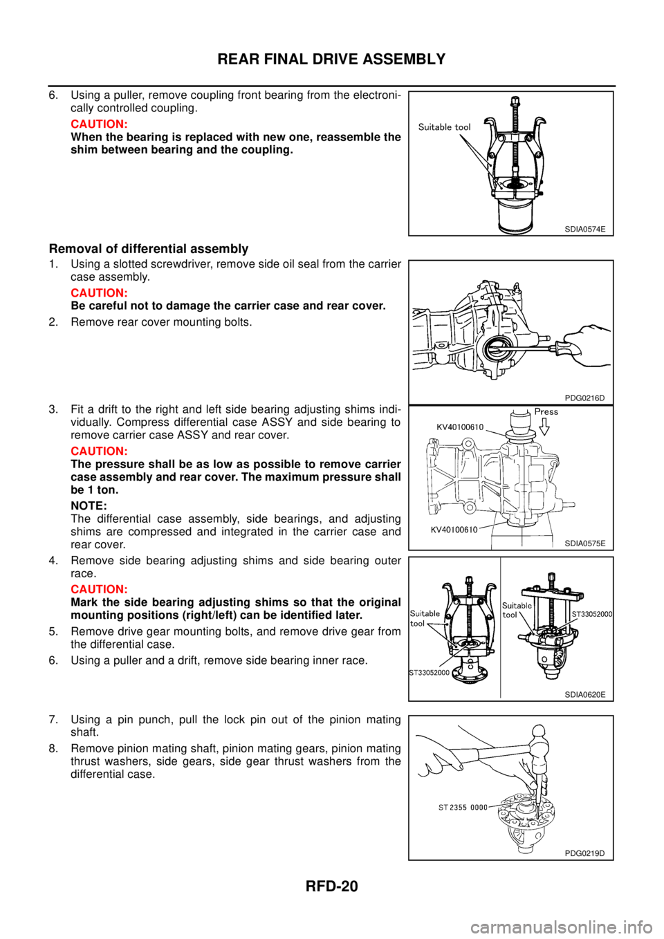
6. Using a puller, remove coupling front bearing from the electroni-
cally controlled coupling.
CAUTION:
When the bearing is replaced with new one, reassemble the
shim between bearing and the coupling.
Removal of differential assembly
1. Using a slotted screwdriver, remove side oil seal from the carrier
case assembly.
CAUTION:
Be careful not to damage the carrier case and rear cover.
2. Remove rear cover mounting bolts.
3. Fit a drift to the right and left side bearing adjusting shims indi-
vidually. Compress differential case ASSY and side bearing to
remove carrier case ASSY and rear cover.
CAUTION:
The pressure shall be as low as possible to remove carrier
case assembly and rear cover. The maximum pressure shall
be 1 ton.
NOTE:
The differential case assembly, side bearings, and adjusting
shims are compressed and integrated in the carrier case and
rear cover.
4. Remove side bearing adjusting shims and side bearing outer
race.
CAUTION:
Mark the side bearing adjusting shims so that the original
mounting positions (right/left) can be identified later.
5. Remove drive gear mounting bolts, and remove drive gear from
the differential case.
6. Using a puller and a drift, remove side bearing inner race.
7. Using a pin punch, pull the lock pin out of the pinion mating
shaft.
8. Remove pinion mating shaft, pinion mating gears, pinion mating
thrust washers, side gears, side gear thrust washers from the
differential case.
SDIA0574E
PDG0216D
SDIA0575E
SDIA0620E
PDG0219D
Page 2848 of 3066

RFD-26
REAR FINAL DRIVE ASSEMBLY
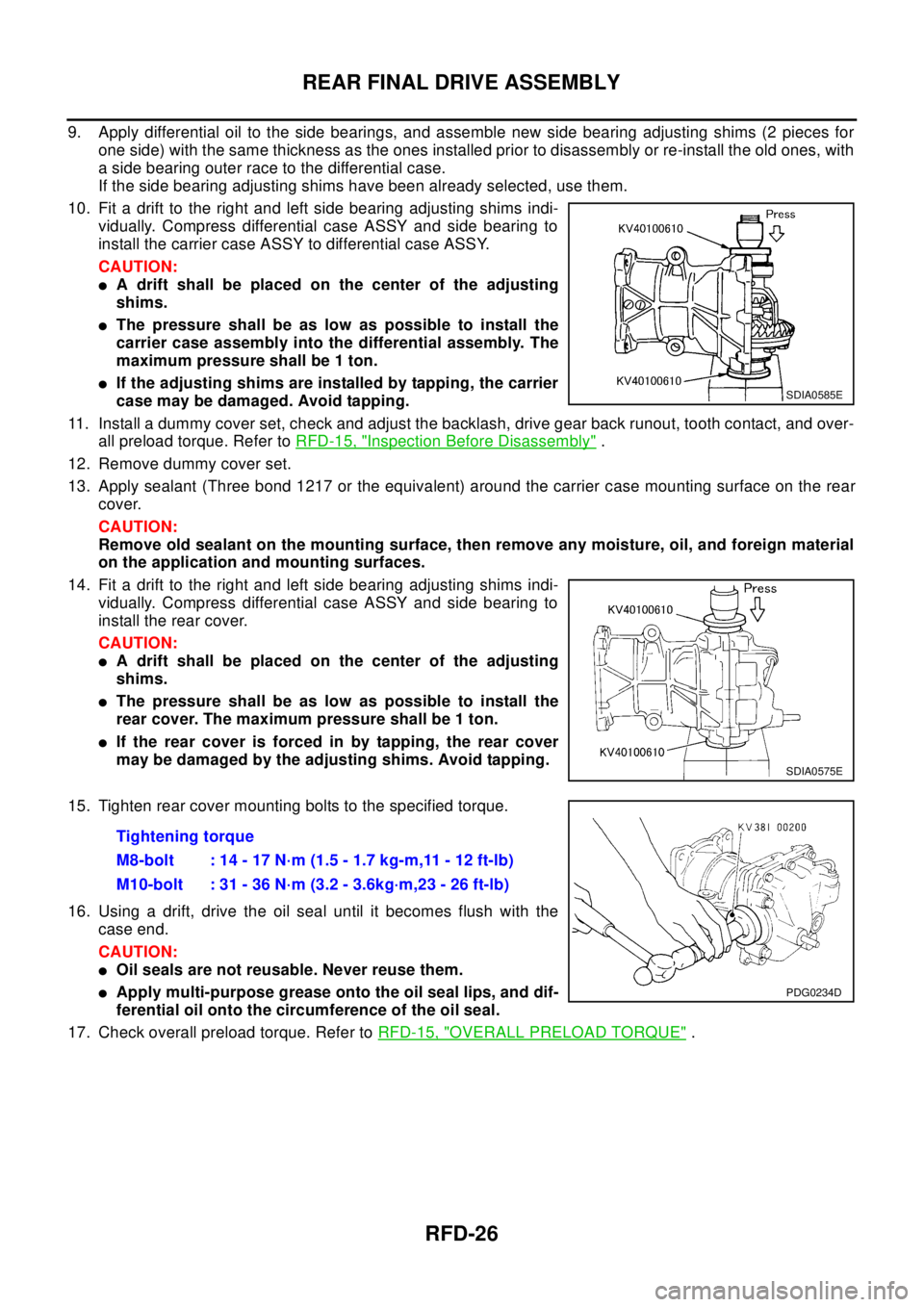
9. Apply differential oil to the side bearings, and assemble new side bearing adjusting shims (2 pieces for
one side) with the same thickness as the ones installed prior to disassembly or re-install the old ones, with
a side bearing outer race to the differential case.
If the side bearing adjusting shims have been already selected, use them.
10. Fit a drift to the right and left side bearing adjusting shims indi-
vidually. Compress differential case ASSY and side bearing to
install the carrier case ASSY to differential case ASSY.
CAUTION:
lA drift shall be placed on the center of the adjusting
shims.
lThepressureshallbeaslowaspossibletoinstallthe
carrier case assembly into the differential assembly. The
maximum pressure shall be 1 ton.
lIf the adjusting shims are installed by tapping, the carrier
case may be damaged. Avoid tapping.
11. Install a dummy cover set, check and adjust the backlash, drive gear back runout, tooth contact, and over-
all preload torque. Refer toRFD-15, "
Inspection Before Disassembly".
12. Remove dummy cover set.
13. Apply sealant (Three bond 1217 or the equivalent) around the carrier case mounting surface on the rear
cover.
CAUTION:
Remove old sealant on the mounting surface, then remove any moisture, oil, and foreign material
on the application and mounting surfaces.
14. Fit a drift to the right and left side bearing adjusting shims indi-
vidually. Compress differential case ASSY and side bearing to
install the rear cover.
CAUTION:
lA drift shall be placed on the center of the adjusting
shims.
lThepressureshallbeaslowaspossibletoinstallthe
rear cover. The maximum pressure shall be 1 ton.
lIf the rear cover is forced in by tapping, the rear cover
may be damaged by the adjusting shims. Avoid tapping.
15. Tighten rear cover mounting bolts to the specified torque.
16. Using a drift, drive the oil seal until it becomes flush with the
case end.
CAUTION:
lOil seals are not reusable. Never reuse them.
lApply multi-purpose grease onto the oil seal lips, and dif-
ferential oil onto the circumference of the oil seal.
17. Check overall preload torque. Refer toRFD-15, "
OVERALL PRELOAD TORQUE".
SDIA0585E
SDIA0575E
Tightening torque
M8-bolt : 14 - 17 N·m (1.5 - 1.7 kg-m,11 - 12 ft-lb)
M10-bolt : 31 - 36 N·m (3.2 - 3.6kg·m,23 - 26 ft-lb)
PDG0234D
Page 2858 of 3066

RSU-6
REAR SUSPENSION ASSEMBLY
On-Vehicle Inspection and Service
EES0007F
Check axle and suspension parts for excessive play, wear, and damage.
lMove rear wheels (RH/LH) to check abnormal free play.
lRetighten all nuts and bolts to the specified torque.
lCheck strut for oil leakage and damage.
Wheel AlignmentEES0007G
DESCRIPTION
lMeasure wheel alignment under unladen conditions. “Unladen conditions” means that fuel, coolant, and
lubricant are full. However, spare tire, jack, and hand tools should be unloaded.
PRELIMINARY INSPECTION
1. Check the tires for improper air pressure and wear.
2. Check road wheels for runout.
3. Check wheel bearing axial endplay.
4. Check strut operation.
5. Check each mounting point of axle and suspension for looseness and deformation.
6. Check each link and arm for cracks, deformation, and other damage.
7. Check the vehicle posture.
CAMBER
Camber is preset at factory and cannot be adjusted.
lIf the camber is not within specification, inspect and replace any damaged or worn rear suspension parts.
TOE-IN
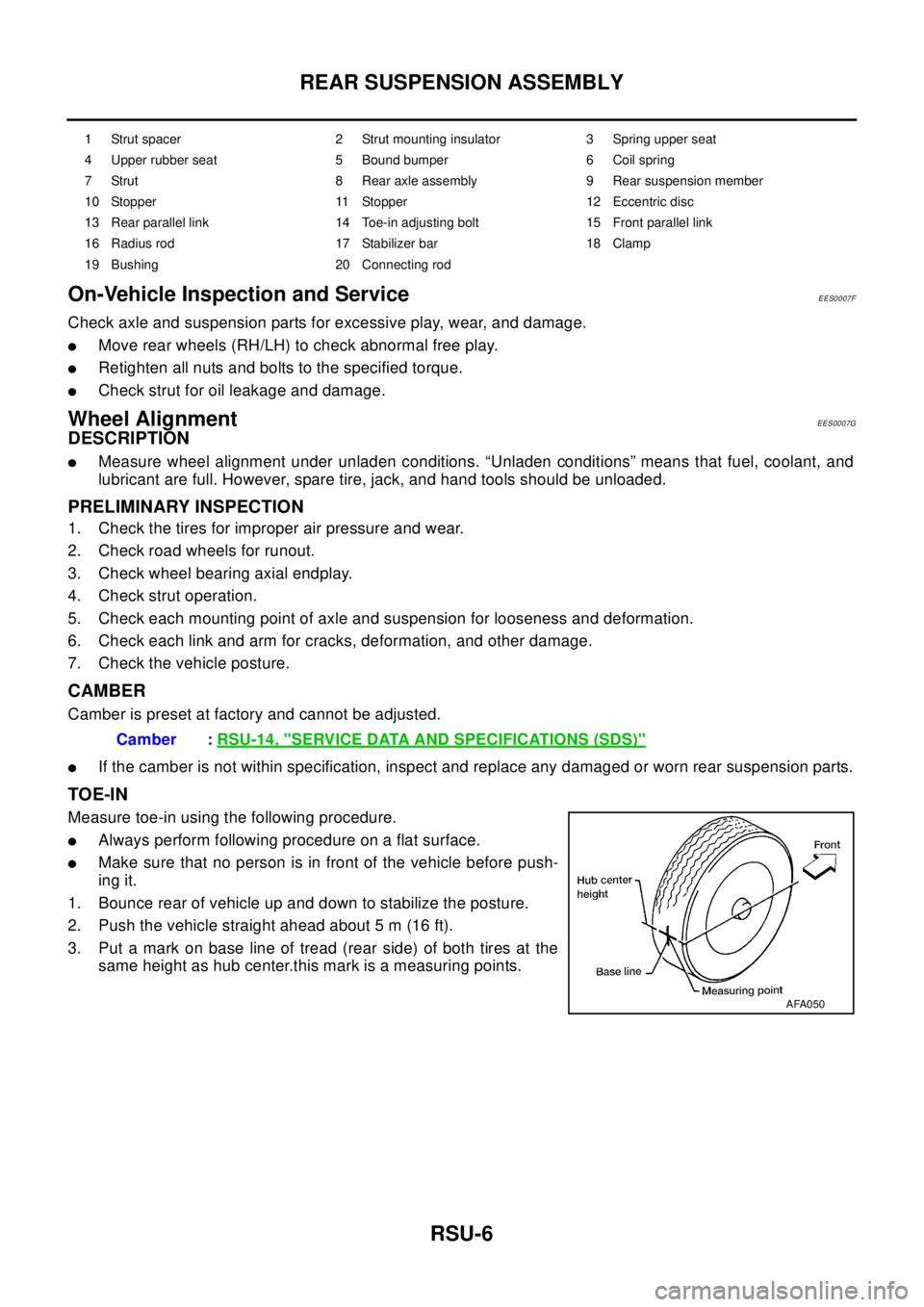
Measure toe-in using the following procedure.
lAlways perform following procedure on a flat surface.
lMake sure that no person is in front of the vehicle before push-
ing it.
1. Bounce rear of vehicle up and down to stabilize the posture.
2. Push the vehicle straight ahead about 5 m (16 ft).
3. Put a mark on base line of tread (rear side) of both tires at the
same height as hub center.this mark is a measuring points.
1 Strut spacer 2 Strut mounting insulator 3 Spring upper seat
4 Upper rubber seat 5 Bound bumper 6 Coil spring
7 Strut 8 Rear axle assembly 9 Rear suspension member
10 Stopper 11 Stopper 12 Eccentric disc
13 Rear parallel link 14 Toe-in adjusting bolt 15 Front parallel link
16 Radius rod 17 Stabilizer bar 18 Clamp
19 Bushing 20 Connecting rod
Camber :RSU-14, "SERVICE DATA AND SPECIFICATIONS (SDS)"
AFA050
Page 3002 of 3066

TF-32
ALL MODE 4X4 SYSTEM
4WD MODE SWITCT
AUTO mode (AUTO indicator lamp ON)
lElectronic control allows optimal distribution of torque to front/rear wheels to match road conditions.
lMakes possible stable driving, with no wheel spin, on snowy roads or other slippery surfaces.
lOn roads which do not require 4WD, it contributes to improved fuel economy by driving in conditions close
to front-wheel drive.
lSensors determine the vehicle's turning condition, and in response tight cornering/braking are controlled
by distributing optimum torque to rear wheels.
NOTE:
lWhen driving in AUTO mode or LOCK mode, if there is a large difference between front and rear wheel
speed which continues for a long time, oil temperature of drive system parts becomes too high and 4WD
warning lamp flashes rapidly. (When 4WD warning lamp flashes, vehicle changes to front-wheel drive
conditions.)
lWhen driving in AUTO mode, 4WD warning lamp may flash slowly if there is a significant difference in
pressure or wear between tires. At this time, vehicle performance is not fully available and cautious driving
is required. (Continues until engine is turned OFF.)
lIf 4WD warning lamp is flashing rapidly, stop vehicle and allow it to idle for some time. Flashing will stop
and AUTO mode will be restored.
lIf the warning lamp flashes slowly during driving but remains OFF after engine is restarted, the system is
normal. If it again flashes slowly after driving for some time, vehicle must be inspected.
lWhen the difference of revolution speed between the front and rear wheel with AUTO mode the shift
switch occasionally changes to LOCK mode automatically. This is not malfunction.
LOCK mode (LOCK indicator lamp and AUTO indicator lamp ON)
lFront/rear wheel torque distribution is fixed, ensuring stable driving when climbing slopes.
lWhen LOCK mode is selected, vehicle will switch automatically to AUTO mode if vehicle speed increases.
If vehicle speed then decreases, the vehicle automatically returns to direct 4-wheel driving conditions.
NOTE:
If there is a significant difference in pressure or wear between tires, full vehicle performance is not available.
Tire conditions are detected, and LOCK mode may be prohibited, or else speeds at which LOCK mode is
enabled may be restricted.
2WD mode (indicator lamps OFF)
Vehicle is in front-wheel drive.
NOTE:
lIf front wheels are slipping in 2WD mode, do not switch to AUTO or LOCK. This can cause difficulties for
the system.
lThe shift switch even if the shift switch is in 2WD mode, the sift switch occasionally automatically change
to 4WD mode depending on the driving condition (For example; Depressing the acceleration firmly). this is
not malfunction. How ever, 4WD mode indicator lamp dose not illuminate.
4WD WARNING LAMP
Turns ON when there is a malfunction in 4WD system. It indicates that fail-safe mode is engaged and vehicle
is in 2WD.
Also turns ON when ignition switch is turned ON, for purpose of bulb check. Turns OFF approximately for 3
seconds after the engine starts if system is normal.
4WD waning lamp indiction
Condition Display 4WD warning lamp
Self-diagnosisWhen self-diagnosis is performed, indicates location of
malfunction by number of flashes.-
Lamp checkTurns ON when engine is started to check for burned-out
lamps.Turns ON when ignition switch
is turned ON. Turns OFF
approximately 3 seconds after
engine start.
4WD system malfunction Turns ON if there is malfunction in 4WD system. ON