Page 2238 of 3502
EM-130
[VQ]
DRIVE BELTS
CAUTION:
�Make sure belt is correctly engaged with the pulley groove.
�Make sure that for engine oil, working fluid and engine coolant do not adhere to belt and each
pulley groove.
2. Adjust belt tension. Refer to EM-128, "
Tension Adjustment" .
3. Tighten each nuts and bolts to the specified torque.
4. Make sure that tension of each belt is within the standard. Refer to EM-128, "
Checking Drive Belts" .
Page 2247 of 3502
INTAKE MANIFOLD
EM-139
[VQ]
C
D
E
F
G
H
I
J
K
L
MA
EM
CAUTION:
Cover engine openings to avoid entry of foreign materials.
INSPECTION AFTER REMOVAL
Surface Distortion
�Check the surface distortion of the intake manifold mating sur-
faces with straightedge and feeler gauge.
�If it exceeds the limit, replace intake manifold.
INSTALLATION
Note the following, and install in the reverse order of removal.
Intake Manifold
�If stud bolts were removed, install them and tighten to the specified torque below.
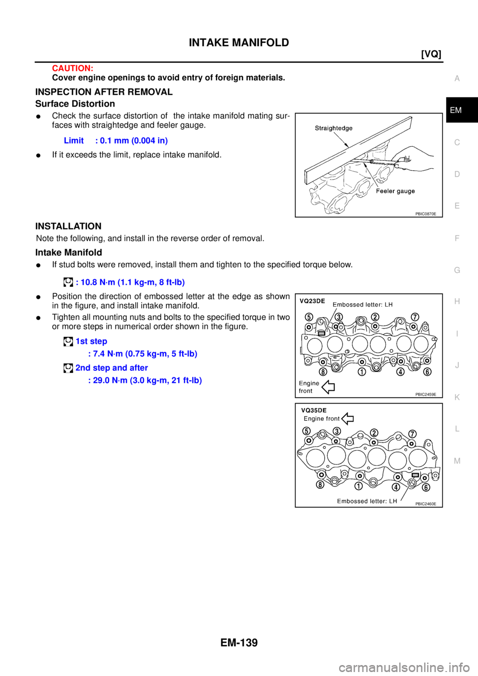
�Position the direction of embossed letter at the edge as shown
in the figure, and install intake manifold.
�Tighten all mounting nuts and bolts to the specified torque in two
or more steps in numerical order shown in the figure.Limit : 0.1 mm (0.004 in)
PBIC0870E
: 10.8 N·m (1.1 kg-m, 8 ft-lb)
1st step
: 7.4 N·m (0.75 kg-m, 5 ft-lb)
2nd step and after
: 29.0 N·m (3.0 kg-m, 21 ft-lb)
PBIC2459E
PBIC2460E
Page 2250 of 3502
EM-142
[VQ]
EXHAUST MANIFOLD AND THREE WAY CATALYST
10. Loosen mounting nuts in the reverse order as shown in the fig-
ure to remove exhaust manifolds (right and left banks).
11. Remove gaskets.
CAUTION:
Cover engine openings to avoid entry of foreign materials.
INSPECTION AFTER REMOVAL
Surface Distortion
�Check the surface distortion of the exhaust manifold mating sur-
faces with straightedge and feeler gauge.
�If it exceeds the limit, replace exhaust manifold.
INSTALLATION
Note the following, and install in the reverse order of removal.
Exhaust Manifold Gasket
Install in the direction indicated in the figure.
PBIC2464E
Limit : 0.3 mm (0.012 in)
PBIC1173E
KBIA1051E
Page 2254 of 3502
![NISSAN TEANA 2003 Service Manual EM-146
[VQ]
OIL PAN AND OIL STRAINER
CAUTION:
�Perform this step when engine is cold.
�Do not spill engine coolant on drive belts.
3. Remove the following:
�Engine cover; Refer to EM-133, "INTAKE MA](/manual-img/5/57392/w960_57392-2253.png "NISSAN TEANA 2003 Service Manual EM-146
[VQ]
OIL PAN AND OIL STRAINER
CAUTION:
�Perform this step when engine is cold.
�Do not spill engine coolant on drive belts.
3. Remove the following:
�Engine cover; Refer to EM-133, \"INTAKE MA")
EM-146
[VQ]
OIL PAN AND OIL STRAINER
CAUTION:
�Perform this step when engine is cold.
�Do not spill engine coolant on drive belts.
3. Remove the following:
�Engine cover; Refer to EM-133, "INTAKE MANIFOLD COLLECTOR" .
�Splash guard (RH)
�Exhaust front tube; Refer to EX-2, "EXHAUST SYSTEM" .
�Drive belts; Refer to EM-128, "DRIVE BELTS" .
4. Remove A/C compressor with piping connected, and temporarily secure it to aside. Refer to ATC-133,
"Components" .
5. Remove three way catalysts (right and left banks) from exhaust manifolds (right and left banks). Refer to
EM-140, "
EXHAUST MANIFOLD AND THREE WAY CATALYST" .
6. Remove oil pressure switch. Refer to LU-20, "
OIL PRESSURE CHECK" .
7. Remove crankshaft position sensor (POS).
CAUTION:
�Handle carefully to avoid dropping and shocks.
�Do not disassemble.
�Do not allow metal powder to adhere to magnetic part at sensor tip.
�Do not place sensor in a location where it is exposed to magnetism.
8. Remove oil filter. Refer to LU-22, "
OIL FILTER" .
9. Remove oil cooler and water pipes (VQ35DE). Refer to LU-23, "
OIL COOLER (VQ35DE)" .
10. Remove oil pan (lower) as follows:
a. Loosen mounting bolts in the reverse order as shown in the fig-
ure.
b. Insert seal cutter (SST) between oil pan (lower) and oil pan
(upper).
CAUTION:
�Be careful not to damage the mating surfaces.
�Do not insert screwdriver, this will damage the mating
surfaces.
c. Slide seal cutter by tapping on the side of the tool with hammer.
Remove oil pan (lower).
PBIC0782E
SEM365ED
Page 2258 of 3502
![NISSAN TEANA 2003 Service Manual EM-150
[VQ]
OIL PAN AND OIL STRAINER
a. Use scraper to remove old liquid gasket from mating surfaces.
�Also remove old liquid gasket from mating surface of oil pan
(upper).
�Remove old liquid gasket](/manual-img/5/57392/w960_57392-2257.png "NISSAN TEANA 2003 Service Manual EM-150
[VQ]
OIL PAN AND OIL STRAINER
a. Use scraper to remove old liquid gasket from mating surfaces.
�Also remove old liquid gasket from mating surface of oil pan
(upper).
�Remove old liquid gasket")
EM-150
[VQ]
OIL PAN AND OIL STRAINER
a. Use scraper to remove old liquid gasket from mating surfaces.
�Also remove old liquid gasket from mating surface of oil pan
(upper).
�Remove old liquid gasket from the bolt holes and thread.
CAUTION:
Do not scratch or damage the mating surfaces when clean-
ing off old liquid gasket.
b. Apply a continuous bead of liquid gasket with tube presser [SST:
WS39930000] to oil pan (lower) as shown in the figure.
Use Genuine Liquid Gasket or equivalent.
CAUTION:
Attaching should be done within 5 minutes after coating.
c. Install oil pan (lower).
�Tighten mounting bolts in numerical order as shown in the fig-
ure.
4. Install oil pan drain plug.
�Refer to the figure of components of former page for installation direction of drain plug washer. Refer to
EM-145, "
Removal and Installation" .
5. Install in the reverse order of removal after this step.
NOTE:
At least 30 minutes after oil pan is installed, pour engine oil.
INSPECTION AFTER INSTALLATION
1. Check the engine oil level and adjust engine oil. Refer to LU-19, "ENGINE OIL" .
2. Start engine, and make sure there is no leak of engine oil.
SEM958F
PBIC2647E
PBIC0782E
Page 2259 of 3502
OIL PAN AND OIL STRAINER
EM-151
[VQ]
C
D
E
F
G
H
I
J
K
L
MA
EM
3. Stop engine and wait for 10 minutes.
4. Check the engine oil level again. Refer to LU-19, "
ENGINE OIL" .
Page 2266 of 3502
![NISSAN TEANA 2003 Service Manual EM-158
[VQ]
FUEL INJECTOR AND FUEL TUBE
CAUTION:
�Upper and lower O-rings are different. Be careful not to confuse them.
�Handle O-ring with bare hands. Do not wear gloves.
�Lubricate O-ring with ne](/manual-img/5/57392/w960_57392-2265.png "NISSAN TEANA 2003 Service Manual EM-158
[VQ]
FUEL INJECTOR AND FUEL TUBE
CAUTION:
�Upper and lower O-rings are different. Be careful not to confuse them.
�Handle O-ring with bare hands. Do not wear gloves.
�Lubricate O-ring with ne")
EM-158
[VQ]
FUEL INJECTOR AND FUEL TUBE
CAUTION:
�Upper and lower O-rings are different. Be careful not to confuse them.
�Handle O-ring with bare hands. Do not wear gloves.
�Lubricate O-ring with new engine oil.
�Do not clean O-ring with solvent.
�Make sure that O-ring and its mating part are free of foreign material.
�When installing O-ring, be careful not to scratch it with tool or fingernails. Also be careful not to
twist or stretch O-ring. If O-ring was stretched while it was being attached, do not insert it
quickly into fuel tube.
�Insert O-ring straight into fuel injector. Do not decenter or twist it.
3. Install fuel injector to fuel tube as follows:
a. Insert clip into clip mounting groove on fuel injector.
�Insert clip so that protrusion “A” of fuel injector matches cut-
out“A” of clip.
CAUTION:
�Do not reuse clip. Replace it with new one.
�Be careful to keep clip from interfering with O-ring. If
interference occurs, replace O-ring.
b. Insert fuel injector into fuel tube with clip attached.
�Insert it while matching it to the axial center.
�Insert fuel injector so that protrusion “B” of fuel tube matches
cutout “B” of clip.
�Make sure that fuel tube flange is securely fixed in flange fix-
ing groove on clip.
c. Make sure that installation is complete by checking that fuel
injector does not rotate or come off.
�Make sure that protrusions of fuel injectors are aligned with
cutouts of clips after installation.
4. Install spacers on intake manifold.
5. Install fuel tube and fuel injector assembly to intake manifold
CAUTION:
Be careful not to let tip of injector nozzle come in contact with other parts.
�Tighten mounting bolts in two steps in numerical order as
shown in the figure.Fuel tube side
VQ23DE : Black
VQ35DE : Blue
Nozzle side
VQ23DE : Green
VQ35DE : Brown
PBIC2545E
1st step
: 10.1 N·m (1.0 kg-m, 7 ft-lb)
2nd step
: 23.6 N·m (2.4 kg-m, 17 ft-lb)
SEC999C
Page 2267 of 3502
![NISSAN TEANA 2003 Service Manual FUEL INJECTOR AND FUEL TUBE
EM-159
[VQ]
C
D
E
F
G
H
I
J
K
L
MA
EM
6. Connect fuel injector harness connector.
7. Install intake manifold collectors (upper and lower). Refer to EM-133, "
INTAKE MANIF](/manual-img/5/57392/w960_57392-2266.png "NISSAN TEANA 2003 Service Manual FUEL INJECTOR AND FUEL TUBE
EM-159
[VQ]
C
D
E
F
G
H
I
J
K
L
MA
EM
6. Connect fuel injector harness connector.
7. Install intake manifold collectors (upper and lower). Refer to EM-133, \"
INTAKE MANIF")
FUEL INJECTOR AND FUEL TUBE
EM-159
[VQ]
C
D
E
F
G
H
I
J
K
L
MA
EM
6. Connect fuel injector harness connector.
7. Install intake manifold collectors (upper and lower). Refer to EM-133, "
INTAKE MANIFOLD COLLECTOR"
.
8. Connect fuel feed hose (with damper).
�Handling procedure of O-ring is the same as that of fuel damper.
�Insert fuel damper straight into fuel tube.
�Tighten mounting bolts evenly in turn.
�After tightening mounting bolts, make sure that there is no gap between flange and fuel tube.
9. Connect quick connector between fuel feed hose (with damper) and centralized under-floor piping con-
nection as follows:
a. Make sure no foreign substances are deposited in and around centralized under-floor piping and quick
connector, and no damage on them.
b. Thinly apply new engine oil around centralized under-floor piping from tip end to spool end.
c. Align center to insert quick connector straightly into centralized under-floor piping.
�Insert quick connector to centralized under-floor piping until
top spool is completely inside quick connector, and 2nd level
spool exposes right below quick connector.
CAUTION:
�Hold “A” position as shown in the figure when inserting
centralized under-floor piping into quick connector.
�Carefully align center to avoid inclined insertion to pre-
vent damage to O-ring inside quick connector.
�Insert until you hear a “click” sound and actually feel the
engagement.
�To avoid misidentification of engagement with a similar
sound, be sure to perform the next step.
d. Pull quick connector by hand holding “A” position. Make sure it is completely engaged (connected) so that
it does not come out from centralized under-floor piping.
e. Install quick connector cap to quick connector.
�Install quick connector cap with arrow on surface facing in
direction of quick connector [fuel feed hose (with damper)
side].
CAUTION:
If quick connector cap cannot be installed smoothly, quick
connector may have not been installed correctly. Check
connection again.
10. Install in the reverse order of removal after this step.
INSPECTION AFTER INSTALLATION
Check Fuel Leakage
1. Turn ignition switch “ON” (with engine stopped). With fuel pressure applied to fuel piping, check for fuel
leakage at connection points.
NOTE:
Use mirrors for checking at points out of clear sight.
2. Start engine. With engine speed increased, check again for fuel leakage at connection points.
CAUTION:
Do not touch engine immediately after stopped, as engine becomes extremely hot.
PBIC2471E
PBIC2893E

![NISSAN TEANA 2003 Service Manual EM-142
[VQ]
EXHAUST MANIFOLD AND THREE WAY CATALYST
10. Loosen mounting nuts in the reverse order as shown in the fig-
ure to remove exhaust manifolds (right and left banks).
11. Remove gaskets.
CAU](/manual-img/5/57392/w960_57392-2249.png "NISSAN TEANA 2003 Service Manual EM-142
[VQ]
EXHAUST MANIFOLD AND THREE WAY CATALYST
10. Loosen mounting nuts in the reverse order as shown in the fig-
ure to remove exhaust manifolds (right and left banks).
11. Remove gaskets.
CAU")
![NISSAN TEANA 2003 Service Manual OIL PAN AND OIL STRAINER
EM-151
[VQ]
C
D
E
F
G
H
I
J
K
L
MA
EM
3. Stop engine and wait for 10 minutes.
4. Check the engine oil level again. Refer to LU-19, "
ENGINE OIL" .](/manual-img/5/57392/w960_57392-2258.png "NISSAN TEANA 2003 Service Manual OIL PAN AND OIL STRAINER
EM-151
[VQ]
C
D
E
F
G
H
I
J
K
L
MA
EM
3. Stop engine and wait for 10 minutes.
4. Check the engine oil level again. Refer to LU-19, \"
ENGINE OIL\" .")