Page 2323 of 3502
![NISSAN TEANA 2003 Service Manual CYLINDER HEAD
EM-215
[VQ]
C
D
E
F
G
H
I
J
K
L
MA
EM
INSPECTION AFTER INSTALLATION
Inspection for Leaks
The following are procedures for checking fluids leak, lubricates leak and exhaust gases leak.](/manual-img/5/57392/w960_57392-2322.png "NISSAN TEANA 2003 Service Manual CYLINDER HEAD
EM-215
[VQ]
C
D
E
F
G
H
I
J
K
L
MA
EM
INSPECTION AFTER INSTALLATION
Inspection for Leaks
The following are procedures for checking fluids leak, lubricates leak and exhaust gases leak.")
CYLINDER HEAD
EM-215
[VQ]
C
D
E
F
G
H
I
J
K
L
MA
EM
INSPECTION AFTER INSTALLATION
Inspection for Leaks
The following are procedures for checking fluids leak, lubricates leak and exhaust gases leak.
�Before starting engine, check oil/fluid levels including engine coolant and engine oil. If less than required
quantity, fill to the specified level. Refer to MA-14, "
RECOMMENDED FLUIDS AND LUBRICANTS" .
�Use procedure below to check for fuel leakage.
–Turn ignition switch “ON” (with engine stopped). With fuel pressure applied to fuel piping, check for fuel
leakage at connection points.
–Start engine. With engine speed increased, check again for fuel leakage at connection points.
�Run engine to check for unusual noise and vibration.
�Warm up engine thoroughly to make sure there is no leakage of fuel, exhaust gases, or any oil/fluids
including engine oil and engine coolant.
�Bleed air from lines and hoses of applicable lines, such as in cooling system.
�After cooling down engine, again check oil/fluid levels including engine oil and engine coolant. Refill to the
specified level, if necessary.
Summary of the inspection items:
* Transmission/transaxle/CVT fluid. power steering fluid, brake fluid, etc.
Disassembly and AssemblyBBS004W8
Item Before starting engine Engine running After engine stopped
Engine coolant Level Leakage Level
Engine oil Level Leakage Level
Other oils and fluid* Level Leakage Level
Fuel Leakage Leakage Leakage
Exhaust gases — Leakage —
PBIC2481E
Page 2334 of 3502
![NISSAN TEANA 2003 Service Manual EM-226
[VQ]
ENGINE ASSEMBLY
6. Remove front suspension member mounting nuts and bolts. Refer to FSU-5, "FRONT SUSPENSION
ASSEMBLY" .
7. Carefully lower engine, transaxle and front suspension member](/manual-img/5/57392/w960_57392-2333.png "NISSAN TEANA 2003 Service Manual EM-226
[VQ]
ENGINE ASSEMBLY
6. Remove front suspension member mounting nuts and bolts. Refer to FSU-5, \"FRONT SUSPENSION
ASSEMBLY\" .
7. Carefully lower engine, transaxle and front suspension member")
EM-226
[VQ]
ENGINE ASSEMBLY
6. Remove front suspension member mounting nuts and bolts. Refer to FSU-5, "FRONT SUSPENSION
ASSEMBLY" .
7. Carefully lower engine, transaxle and front suspension member assembly. When performing work,
observe the following caution.
CAUTION:
�Confirm there is no interference with vehicle.
�Make sure that all connection points have been disconnected.
�Keep in mind the center of vehicle gravity changes. If necessary, use jack(s) to support vehicle
at rear jacking point(s) to prevent it from falling it off the lift.
Separation Work
1. Remove power steering oil pump, power steering piping and power steering bracket from engine and tran-
saxle assembly. Refer to PS-39, "
HYDRAULIC LINE" .
2. Remove starter motor. Refer to SC-14, "
STARTING SYSTEM" .
3. Disconnect harness connector of engine mounting insulators (front and rear).
4. Remove engine mounting (front) and engine mounting (rear) through-bolts.
5. Lift with hoist and separate engine and transaxle assembly from front suspension member.
CAUTION:
Before and during this lifting, always make sure that any harnesses are not connected.
6. Remove each engine mounting insulator and each engine mounting bracket from engine, transaxle and
front suspension member.
7. Separate engine and transaxle. Refer to AT- 2 4 1 , "
TRANSAXLE ASSEMBLY" (A/T), CVT-193, "TRAN-
SAXLE ASSEMBLY" (CVT).
INSTALLATION
Note the following, and install in the reverse order of removal.
�Do not allow engine mounting insulator to be damage and careful no engine oil gets on it.
�For a path with a specified installation orientation, refer to component figure in EM-223, "Removal and
Installation" .
�Make sure all engine mounting insulators are seated properly, then tighten nuts and bolts.
INSPECTION AFTER INSTALLATION
Inspection for Leaks
The following are procedures for checking fluids leak, lubricates leak and exhaust gases leak.
�Before starting engine, check oil/fluid levels including engine coolant and engine oil. If less than required
quantity, fill to the specified level. Refer to MA-14, "
RECOMMENDED FLUIDS AND LUBRICANTS" .
�Use procedure below to check for fuel leakage.
–Turn ignition switch “ON” (with engine stopped). With fuel pressure applied to fuel piping, check for fuel
leakage at connection points.
–Start engine. With engine speed increased, check again for fuel leakage at connection points.
�Run engine to check for unusual noise and vibration.
�Warm up engine thoroughly to make sure there is no leakage of fuel, exhaust gases, or any oil/fluids
including engine oil and engine coolant.
�Bleed air from lines and hoses of applicable lines, such as in cooling system.
�After cooling down engine, again check oil/fluid levels including engine oil and engine coolant. Refill to the
specified level, if necessary.
Page 2343 of 3502
![NISSAN TEANA 2003 Service Manual CYLINDER BLOCK
EM-235
[VQ]
C
D
E
F
G
H
I
J
K
L
MA
EM
b. Install thrust bearings to the both sides of the No. 3 journal hous-
ing on cylinder block and main bearing cap.
�Install thrust bearings with](/manual-img/5/57392/w960_57392-2342.png "NISSAN TEANA 2003 Service Manual CYLINDER BLOCK
EM-235
[VQ]
C
D
E
F
G
H
I
J
K
L
MA
EM
b. Install thrust bearings to the both sides of the No. 3 journal hous-
ing on cylinder block and main bearing cap.
�Install thrust bearings with")
CYLINDER BLOCK
EM-235
[VQ]
C
D
E
F
G
H
I
J
K
L
MA
EM
b. Install thrust bearings to the both sides of the No. 3 journal hous-
ing on cylinder block and main bearing cap.
�Install thrust bearings with the oil groove facing crankshaft
arm (outside).
�Install thrust bearing with a protrusion on one end on cylinder
block, and thrust bearing with a protrusion at center on main
bearing cap. Align each protrusion with mating notch.
c. Install main bearings paying attention to the direction.
�Main bearing with oil hole and groove goes on cylinder block.
The one without them goes on main bearing cap.
�Before installing main bearings, apply engine oil to the bear-
ing surface (inside). Do not apply engine oil to the back sur-
face, but thoroughly clean it.
�When installing, align main bearing stopper protrusion to cut-
out of cylinder block and main bearing caps.
�Ensure the oil holes on cylinder block and those on the corre-
sponding bearing are aligned.
5. Install crankshaft to cylinder block.
�While turning crankshaft by hand, check that it turns smoothly.
6. Install main bearing caps.
�Main bearing caps are identified by identification mark cast on
them. For installation, face front mark to front side.
NOTE:
Main bearing cap cannot be replaced as a single part, because it
is machined together with cylinder block.
7. Install main bearing beam. (VQ35DE)
�Install main bearing beam with front mark facing downward (oil pan side).
�Install main bearing beam with front mark facing front of
engine.
8. Inspect outer diameter of main bearing cap bolts. Refer to EM-253, "
MAIN BEARING CAP BOLT OUTER
DIAMETER" .
PBIC0807E
PBIC2489E
SEM456G
PBIC2490E
Page 2344 of 3502
![NISSAN TEANA 2003 Service Manual EM-236
[VQ]
CYLINDER BLOCK
9. Tighten main bearing cap bolts in numerical order as shown in
the figure as follows:
a. Apply new engine oil to threads and seat surfaces of main bear-
ing cap bolts.
b](/manual-img/5/57392/w960_57392-2343.png "NISSAN TEANA 2003 Service Manual EM-236
[VQ]
CYLINDER BLOCK
9. Tighten main bearing cap bolts in numerical order as shown in
the figure as follows:
a. Apply new engine oil to threads and seat surfaces of main bear-
ing cap bolts.
b")
EM-236
[VQ]
CYLINDER BLOCK
9. Tighten main bearing cap bolts in numerical order as shown in
the figure as follows:
a. Apply new engine oil to threads and seat surfaces of main bear-
ing cap bolts.
b. Tighten main bearing cap bolts in several different steps.
c. Turn all main bearing cap bolts 90 degrees clockwise. (Angle
tightening)
CAUTION:
Use angle wrench [SST: KV10112100] to check tightening
angle. Do not make judgment by visual inspection.
�After installing main bearing cap bolts, make sure that crank-
shaft can be rotated smoothly by hand.
�Check crankshaft end play. Refer to EM-245, "CRANKSHAFT
END PLAY" .
10. Inspect outer diameter of connecting rod bolts. Refer to EM-253, "
CONNECTING ROD BOLT OUTER
DIAMETER" .
11. Install piston to connecting rod as follows:
a. Using snap ring pliers, install new snap ring to the groove of piston rear side.
�Insert it fully into groove to install.
b. Install piston to connecting rod.
�Using industrial use drier or similar tool, heat piston until piston pin can be pushed in by hand without
excess force [approx. 60 to 70°C (140 to 158°F)]. From the front to the rear, insert piston pin into piston
and connecting rod.
�Assemble so that the front mark on the piston head and the
cylinder number on connecting rod are positioned as shown in
the figure.
c. Install new snap ring to the groove of the piston front side.
�Insert it fully into groove to install.
�After installing, make sure that connecting rod moves
smoothly.
12. Using piston ring expander (commercial service tool), install pis-
ton rings.
CAUTION:
�When installing piston rings, be careful not to damage
piston.
�Be careful not to damage piston rings by expending them
excessively. : 35.3 N·m (3.6 kg-m, 26 ft-lb)
PBIC1800E
PBIC0921E
SEM838F
PBIC0087E
Page 2346 of 3502
![NISSAN TEANA 2003 Service Manual EM-238
[VQ]
CYLINDER BLOCK
�Match the stamped cylinder number marks on connecting rod
with those on connecting rod bearing cap to install.
�Be sure that front mark on connecting rod bearing cap is f](/manual-img/5/57392/w960_57392-2345.png "NISSAN TEANA 2003 Service Manual EM-238
[VQ]
CYLINDER BLOCK
�Match the stamped cylinder number marks on connecting rod
with those on connecting rod bearing cap to install.
�Be sure that front mark on connecting rod bearing cap is f")
EM-238
[VQ]
CYLINDER BLOCK
�Match the stamped cylinder number marks on connecting rod
with those on connecting rod bearing cap to install.
�Be sure that front mark on connecting rod bearing cap is fac-
ing front of engine.
16. Tighten connecting rod nuts (VQ23DE) or connecting rod bolts (VQ35DE) as follows:
a. Apply engine oil to the threads and seats of connecting rod nuts or bolts.
b. Tighten connecting rod nuts or bolts.
c. Then tighten all connecting rod nuts or bolts 90 degrees clock-
wise. (Angle tightening)
CAUTION:
Use angle wrench [SST: KV10112100] to check tightening
angle. Do not make judgment by visual inspection.
�After tightening connecting rod nuts or bolts, make sure that
crankshaft rotates smoothly.
17. Install rear oil seal retainer to cylinder block.
�Apply new engine oil to both oil seal lip and dust seal lip.
�Apply a continuous bead of liquid gasket with tube presser
[SST: WS39930000] to rear oil seal retainer as shown in the
figure.
Use Genuine Liquid Gasket or equivalent.
CAUTION:
Replace with a new part.
NOTE:
Regard both rear oil seal and retainer as an assembly.
18. Install pilot converter.
�With drift [outer diameter: approx. 33 mm (1.30 in)], press-fit
as far as it will go.
PBIC0809E
: 19.6 N·m (2.0 kg-m, 14 ft-lb)
SEM953E
PBIC2649E
PBIC0899E
Page 2379 of 3502
EX-1
EXHAUST SYSTEM
B ENGINE
CONTENTS
C
D
E
F
G
H
I
J
K
L
M
SECTION EX
A
EX
EXHAUST SYSTEM
EXHAUST SYSTEM ................................................... 2Checking Exhaust System ........................................ 2
Removal and Installation .......................................... 2
REMOVAL ............................................................. 3
INSTALLATION ..................................................... 3
INSPECTION AFTER INSTALLATION .................. 4
Page 2380 of 3502
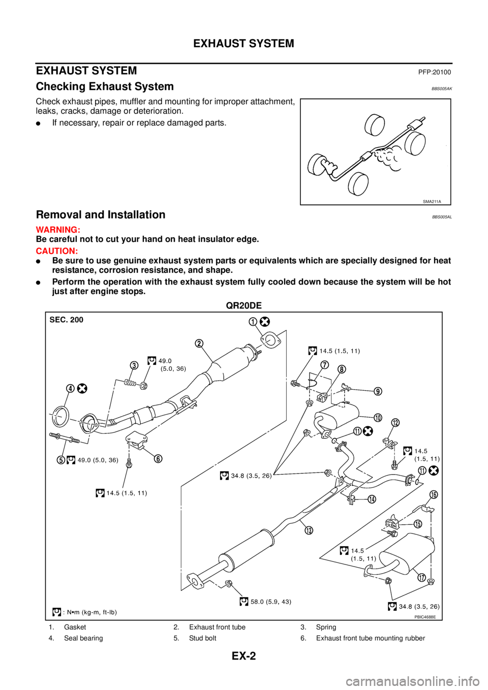
EX-2
EXHAUST SYSTEM
EXHAUST SYSTEMPFP:20100
Checking Exhaust SystemBBS005AK
Check exhaust pipes, muffler and mounting for improper attachment,
leaks, cracks, damage or deterioration.
�If necessary, repair or replace damaged parts.
Removal and InstallationBBS005AL
WARNING:
Be careful not to cut your hand on heat insulator edge.
CAUTION:
�Be sure to use genuine exhaust system parts or equivalents which are specially designed for heat
resistance, corrosion resistance, and shape.
�Perform the operation with the exhaust system fully cooled down because the system will be hot
just after engine stops.
QR20DE
SMA211A
PBIC4688E
1. Gasket 2. Exhaust front tube 3. Spring
4. Seal bearing 5. Stud bolt 6. Exhaust front tube mounting rubber
Page 2382 of 3502

EX-4
EXHAUST SYSTEM
�When installing heat insulator avoid large gaps or interference between heat insulator and each
exhaust pipe.
�Remove deposits from the sealing surface of each connection. Connect them securely to avoid
gas leakage.
�Temporarily tighten mounting nuts and bolts on the exhaust manifold side, and mounting bolts
and nuts on the vehicle side. Check each part for unusual interference, and then tighten them to
the specified torque.
�When installing each mounting rubber, avoid twisting or unusual extension in up/down and right/
left directions.
Seal Bearing (QR20DE)
1. Securely insert seal bearing into exhaust manifold and three
way catalyst assembly side in the direction as shown in the fig-
ure.
CAUTION:
Be careful not to damage seal bearing surface when install-
ing.
2. With spring large diameter side facing to exhaust front tube
flange, tighten mounting nut.
3. Make sure that stud bolt does not interfere with flange of
exhaust front tube.
INSPECTION AFTER INSTALLATION
�Make sure that clearance between tail tube and rear bumper is even.
�With engine running, check exhaust tube joints for gas leakage and unusual noises.
�Make sure that mounting brackets and mounting rubbers are installed properly and free from undue
stress. Improper installation could result in excessive noise and vibration.
PBIC2432E