Page 3381 of 3502

TROUBLE DIAGNOSIS
SRS-7
C
D
E
F
G
I
J
K
L
MA
B
SRS
TROUBLE DIAGNOSISPFP:00004
Trouble Diagnosis IntroductionBHS00043
CAUTION:
�Do not use electrical test equipment on any circuit related to the SRS unless instructed to in this
Service Manual. SRS wiring harnesses can be identified by yellow and/or orange harnesses or
harness connectors.
�Do not attempt to repair, splice or modify the SRS wiring harness. If the harness is damaged,
replace it with a new one.
�Keep ground portion clean.
DIAGNOSIS FUNCTION
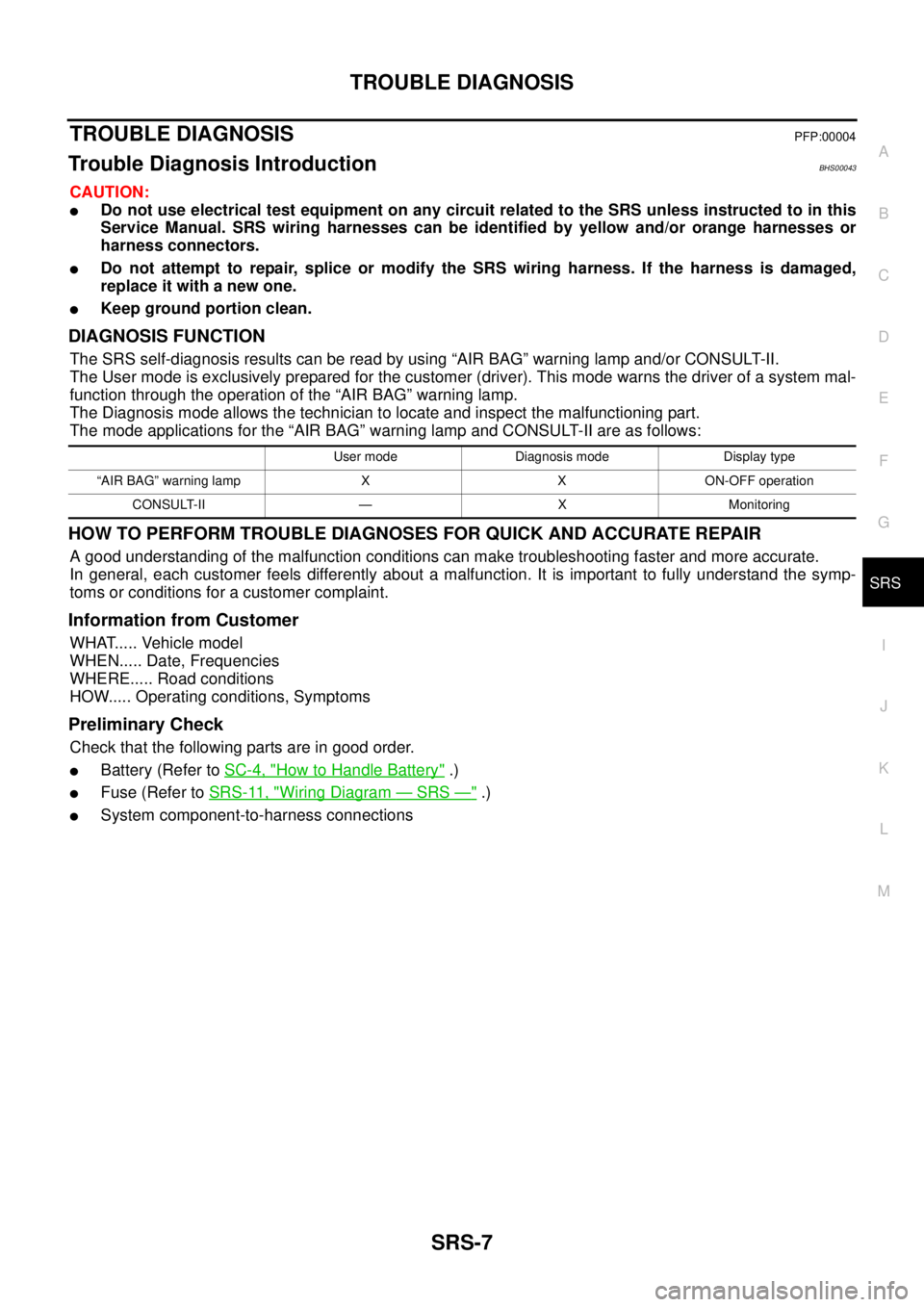
The SRS self-diagnosis results can be read by using “AIR BAG” warning lamp and/or CONSULT-II.
The User mode is exclusively prepared for the customer (driver). This mode warns the driver of a system mal-
function through the operation of the “AIR BAG” warning lamp.
The Diagnosis mode allows the technician to locate and inspect the malfunctioning part.
The mode applications for the “AIR BAG” warning lamp and CONSULT-II are as follows:
HOW TO PERFORM TROUBLE DIAGNOSES FOR QUICK AND ACCURATE REPAIR
A good understanding of the malfunction conditions can make troubleshooting faster and more accurate.
In general, each customer feels differently about a malfunction. It is important to fully understand the symp-
toms or conditions for a customer complaint.
Information from Customer
WHAT..... Vehicle model
WHEN..... Date, Frequencies
WHERE..... Road conditions
HOW..... Operating conditions, Symptoms
Preliminary Check
Check that the following parts are in good order.
�Battery (Refer to SC-4, "How to Handle Battery" .)
�Fuse (Refer to SRS-11, "Wiring Diagram — SRS —" .)
�System component-to-harness connections
User mode Diagnosis mode Display type
“AIR BAG” warning lamp X X ON-OFF operation
CONSULT-II — X Monitoring
Page 3456 of 3502

WW-18
FRONT WIPER AND WASHER SYSTEM
How to Perform Trouble DiagnosesBKS001TN
1. Confirm the symptoms and customer complaint.
2. Understand operation description and function description. Refer to WW-4, "
System Description" .
3. Perform the Preliminary Check. Refer to WW-18, "
Preliminary Check" .
4. Check symptom and repair or replace the cause of malfunction.
5. Does the front wiper and washer operate normally? If YES, GO TO 6. If NO, GO TO 4.
6. INSPECTION END
Preliminary CheckBKS001TO
CHECK POWER SUPPLY AND GROUND CIRCUIT
1. CHECK FUSES AND FUSIBLE LINK
Check for blown fuses and fusible link.
Refer to WW-11, "Wiring Diagram — WIPER —" .
OK or NG
OK >> GO TO 2
NG >> If fuse or fusible link is blown, be sure to eliminate cause of malfunction before installing new fuse
or fusible link. Refer to PG-3, "
POWER SUPPLY ROUTING CIRCUIT" .
2. CHECK POWER SUPPLY CIRCUIT
1. Turn ignition switch OFF.
2. Disconnect BCM connectors.
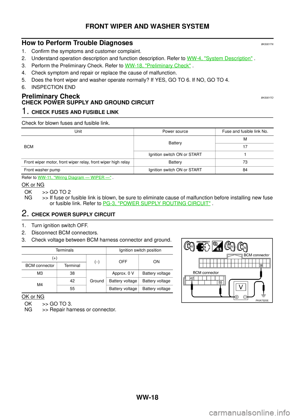
3. Check voltage between BCM harness connector and ground.
OK or NG
OK >> GO TO 3.
NG >> Repair harness or connector.
Unit Power source Fuse and fusible link No.
BCMBatteryM
17
Ignition switch ON or START 1
Front wiper motor, front wiper relay, front wiper high relay Battery 73
Front washer pump Ignition switch ON or START 84
Terminals Ignition switch position
(+)
(−)OFF ON
BCM connector Terminal
M3 38
GroundApprox. 0 V Battery voltage
M442 Battery voltage Battery voltage
55 Battery voltage Battery voltage
PKIA7520E
Page 3487 of 3502

HEADLAMP WASHER
WW-49
C
D
E
F
G
H
I
J
L
MA
B
WW
Preliminary CheckBKS002CH
CHECK POWER SUPPLY AND GROUND CIRCUIT
1. CHECK FUSES AND FUSIBLE LINK
Check for blown fuses and fusible link.
Refer to WW-43, "Wiring Diagram — HLC —" .
OK or NG
OK >> GO TO 2
NG >> If fuse or fusible link is blown, be sure to eliminate cause of malfunction before installing new fuse
or fusible link. Refer to PG-3, "
POWER SUPPLY ROUTING CIRCUIT" .
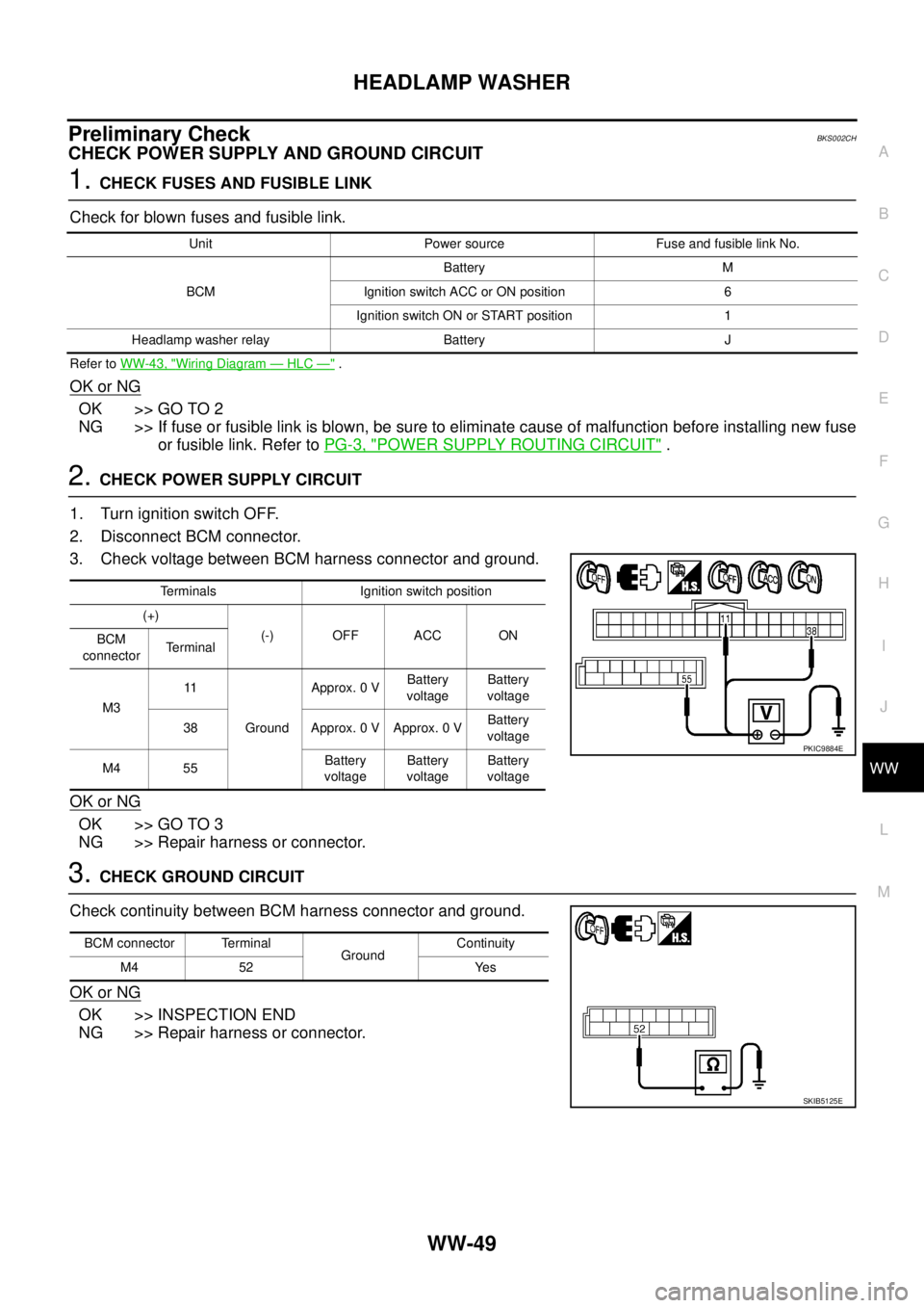
2. CHECK POWER SUPPLY CIRCUIT
1. Turn ignition switch OFF.
2. Disconnect BCM connector.
3. Check voltage between BCM harness connector and ground.
OK or NG
OK >> GO TO 3
NG >> Repair harness or connector.
3. CHECK GROUND CIRCUIT
Check continuity between BCM harness connector and ground.
OK or NG
OK >> INSPECTION END
NG >> Repair harness or connector.
Unit Power source Fuse and fusible link No.
BCMBattery M
Ignition switch ACC or ON position 6
Ignition switch ON or START position 1
Headlamp washer relay Battery J
Terminals Ignition switch position
(+)
(-) OFF ACC ON
BCM
connectorTe r m i n a l
M311
GroundApprox. 0 VBattery
voltageBattery
voltage
38 Approx. 0 V Approx. 0 VBattery
voltage
M4 55Battery
voltageBattery
voltageBattery
voltage
PKIC9884E
BCM connector Terminal
GroundContinuity
M4 52 Yes
SKIB5125E