Page 2470 of 3502

GI-24
SERVICE INFORMATION FOR ELECTRICAL INCIDENT
SERVICE INFORMATION FOR ELECTRICAL INCIDENTPFP:00000
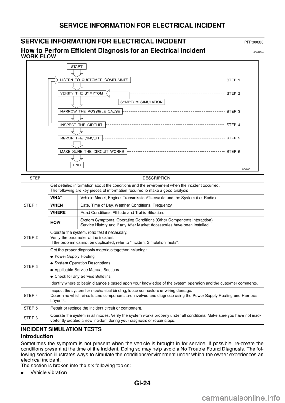
How to Perform Efficient Diagnosis for an Electrical IncidentBAS0007I
WORK FLOW
INCIDENT SIMULATION TESTS
Introduction
Sometimes the symptom is not present when the vehicle is brought in for service. If possible, re-create the
conditions present at the time of the incident. Doing so may help avoid a No Trouble Found Diagnosis. The fol-
lowing section illustrates ways to simulate the conditions/environment under which the owner experiences an
electrical incident.
The section is broken into the six following topics:
�Vehicle vibration
SGI838
STEP DESCRIPTION
STEP 1Get detailed information about the conditions and the environment when the incident occurred.
The following are key pieces of information required to make a good analysis:
WHATVehicle Model, Engine, Transmission/Transaxle and the System (i.e. Radio).
WHENDate, Time of Day, Weather Conditions, Frequency.
WHERERoad Conditions, Altitude and Traffic Situation.
HOWSystem Symptoms, Operating Conditions (Other Components Interaction).
Service History and if any After Market Accessories have been installed.
STEP 2Operate the system, road test if necessary.
Verify the parameter of the incident.
If the problem cannot be duplicated, refer to “Incident Simulation Tests”.
STEP 3Get the proper diagnosis materials together including:
�Power Supply Routing
�System Operation Descriptions
�Applicable Service Manual Sections
�Check for any Service Bulletins
Identify where to begin diagnosis based upon your knowledge of the system operation and the customer comments.
STEP 4Inspect the system for mechanical binding, loose connectors or wiring damage.
Determine which circuits and components are involved and diagnose using the Power Supply Routing and Harness
Layouts.
STEP 5 Repair or replace the incident circuit or component.
STEP 6Operate the system in all modes. Verify the system works properly under all conditions. Make sure you have not inad-
vertently created a new incident during your diagnosis or repair steps.
Page 3248 of 3502
SC-30
CHARGING SYSTEM
Removal and InstallationBKS0027E
VQ23DE AND VQ35DE MODELS
Removal
1. Disconnect negative battery cable.
2. Remove engine undercover, using power tools.
3. Remove radiator. Refer to CO-37, "
RADIATOR" in “ENGINE COOLING SYSTEM (CO)” section.
4. Remove alternator and air conditioner compressor belt. Refer to EM-129, "
Removal and Installation" in
“ENGINE MECHANICAL (EM)” section.
5. Remove idler pulley.
6. Remove alternator mounting nut, using power tools.
7. Remove through bolt.
8. Disconnect alternator connector.
9. Remove B terminal nut.
10. Remove ground harness clip and ground harness mounting nut.
1. Through-bolt 2. Cylinder block 3. Timing chain case
4. Alternator mounting nut 5. Alternator 6. Alternator connector
7. B terminal harness 8. B terminal nut 9. Alternator mounting bolt
10. Alternator bracket 11. Alternator bracket mounting bolt
PKIA2926J
PKIA2431E
PKIA2432E
Page 3249 of 3502
CHARGING SYSTEM
SC-31
C
D
E
F
G
H
I
J
L
MA
B
SC
11. Remove alternator mounting bolt, using power tools.
12. Remove alternator bracket mounting bolt and alternator bracket.
13. Remove alternator to the direction of upper side the vehicle.
Installation
Note the following, and install in the reverse order of removal.
�Install alternator, and check tension of belt. Refer to EM-128, "Checking Drive Belts" in “ENGINE
MECHANICAL (EM)” section.
CAUTION:
Be sure to tighten B terminal nut carefully.
PKIA2433E
Page 3250 of 3502
SC-32
CHARGING SYSTEM
QR20DE MODELS
Removal
1. Disconnect negative battery cable.
2. Remove drive belt. Refer to EM-14, "
Removal and Installation" .
3. Remove IPDM E/R bracket mounting bolts.
4. Slide IPDM E/R to the direction of arrow.
5. Disconnect alternator connector.
6. Remove B terminal nut.
7. Remove ground harness clip and ground harness bolt.
8. Remove alternator mounting bolts, using power tools.
9. Remove alternator to the direction of upper side the vehicle.
Installation
Note the following, and install in the reverse order of removal.
�Install alternator, and check tension of belt. Refer to EM-14, "Checking Drive Belts" in “ENGINE
MECHANICAL (EM)” section.
CAUTION:
Be sure to tighten B terminal nut carefully.
1. Alternator bracket 2. Alternator mounting bolt (upper) 3. Alternator mounting bolt (lower)
4. Alternator 5. B terminal harness 6. B terminal nut
7. Alternator connector
PKIA2930J
PKIA4811E
PKIA4812E