Page 2180 of 3502
![NISSAN TEANA 2003 Service Manual EM-72
[QR]
CYLINDER HEAD
�Compress valve spring with valve spring compressor, attach-
ment and adapter (SST). Install valve collet with magnet
hand.
CAUTION:
When working, be careful not to damage v](/manual-img/5/57392/w960_57392-2179.png "NISSAN TEANA 2003 Service Manual EM-72
[QR]
CYLINDER HEAD
�Compress valve spring with valve spring compressor, attach-
ment and adapter (SST). Install valve collet with magnet
hand.
CAUTION:
When working, be careful not to damage v")
EM-72
[QR]
CYLINDER HEAD
�Compress valve spring with valve spring compressor, attach-
ment and adapter (SST). Install valve collet with magnet
hand.
CAUTION:
When working, be careful not to damage valve lifter
holes.
�Tap valve stem edge lightly with plastic hammer after installa-
tion to check its installed condition.
8. Install valve lifter.
�Install it in the original position.
9. Install spark plug tube if removed.
�Press-fit it into cylinder head with the following procedure:
a. Remove old liquid gasket from cylinder head side installation
hole.
b. Apply sealant all round on spark plug tube within approximately
12 mm (0.47 in) width from edge of spark plug tube on the
press-fit side.
Use Thread Locking Sealant or equivalent.
c. Using drift, press-fit spark plug tube so that height is as same as
“H” shown in the figure.
CAUTION:
�When press-fitting, be careful not to deform spark plug tube.
�After press-fitting, wipe off any protruding thread locking sealant on top surface of cylinder
head.
10. Install spark plug with spark plug wrench (commercial service tool).
Inspection After DisassemblyBBS0059E
VALVE DIMENSIONS
�Check dimensions of each valve. For dimensions, refer to EM-
109, "Valve Dimensions" .
�If dimensions are out of the standard, replace valve.
PBIC1791E
Standard press-fit height “H”
: 41.2 - 42.2 mm (1.622 - 1.661 in)
PBIC2636E
SEM188A
Page 2189 of 3502
CYLINDER BLOCK
EM-81
[QR]
C
D
E
F
G
H
I
J
K
L
MA
EM
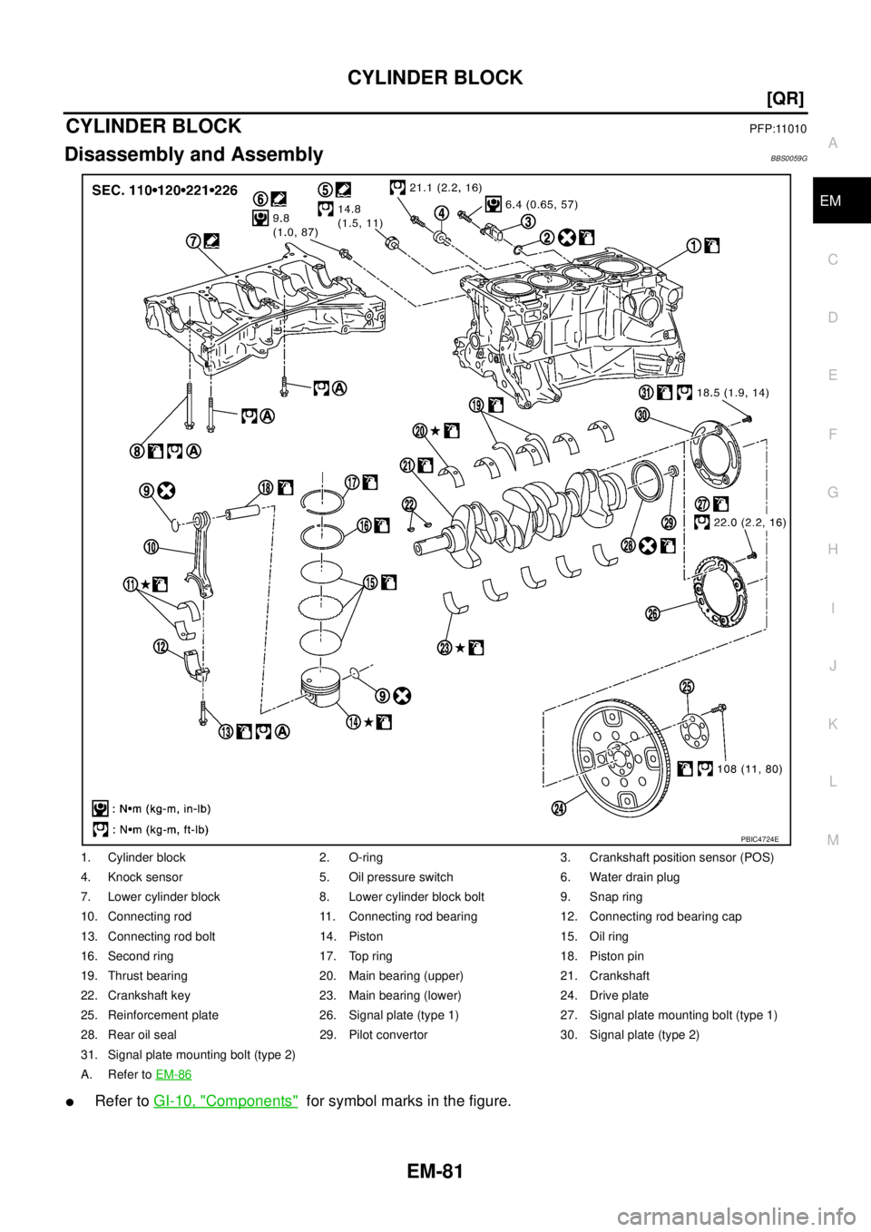
CYLINDER BLOCKPFP:11010
Disassembly and AssemblyBBS0059G
�Refer to GI-10, "Components" for symbol marks in the figure.
1. Cylinder block 2. O-ring 3. Crankshaft position sensor (POS)
4. Knock sensor 5. Oil pressure switch 6. Water drain plug
7. Lower cylinder block 8. Lower cylinder block bolt 9. Snap ring
10. Connecting rod 11. Connecting rod bearing 12. Connecting rod bearing cap
13. Connecting rod bolt 14. Piston 15. Oil ring
16. Second ring 17. Top ring 18. Piston pin
19. Thrust bearing 20. Main bearing (upper) 21. Crankshaft
22. Crankshaft key 23. Main bearing (lower) 24. Drive plate
25. Reinforcement plate 26. Signal plate (type 1) 27. Signal plate mounting bolt (type 1)
28. Rear oil seal 29. Pilot convertor 30. Signal plate (type 2)
31. Signal plate mounting bolt (type 2)
A. Refer to EM-86
PBIC4724E
Page 2190 of 3502
![NISSAN TEANA 2003 Service Manual EM-82
[QR]
CYLINDER BLOCK
NOTE:
There exist different signal plates because of concurrent settings. Consequently, there are two kinds of crank
shafts and signal plate bolts.
DISASSEMBLY
1. Remove en](/manual-img/5/57392/w960_57392-2189.png "NISSAN TEANA 2003 Service Manual EM-82
[QR]
CYLINDER BLOCK
NOTE:
There exist different signal plates because of concurrent settings. Consequently, there are two kinds of crank
shafts and signal plate bolts.
DISASSEMBLY
1. Remove en")
EM-82
[QR]
CYLINDER BLOCK
NOTE:
There exist different signal plates because of concurrent settings. Consequently, there are two kinds of crank
shafts and signal plate bolts.
DISASSEMBLY
1. Remove engine and transaxle assembly from vehicle, and separate transaxle from engine. Refer to EM-
77, "ENGINE ASSEMBLY" .
2. Mount engine on engine stand [SST: ST0501S000] with the following procedure:
a. Remove oil pressure switch on right side of cylinder block. Refer to LU-7, "
OIL PRESSURE CHECK" .
b. Remove rear engine mounting bracket. Refer to EM-77, "
ENGINE ASSEMBLY" .
c. Install engine sub-attachment (SST) and engine stand shaft
[SST: KV10106500] to right side of cylinder block.
�Do not use bolt hole at the upper right looking from bolt inser-
tion side as shown in the figure.
�Machine a bolt hole at the lower right of the engine sub-
attachment looking from bolt insertion side as shown in the
figure.
d. Lift engine, and mount it onto the engine stand.
KBIA0060E
SBIA0272E
KBIA0140E
Page 2191 of 3502
![NISSAN TEANA 2003 Service Manual CYLINDER BLOCK
EM-83
[QR]
C
D
E
F
G
H
I
J
K
L
MA
EM
�A widely use engine stand can be used.
CAUTION:
Use engine stand that has a load capacity [approximately
150 kg (331 lb) or more] large enough fo](/manual-img/5/57392/w960_57392-2190.png "NISSAN TEANA 2003 Service Manual CYLINDER BLOCK
EM-83
[QR]
C
D
E
F
G
H
I
J
K
L
MA
EM
�A widely use engine stand can be used.
CAUTION:
Use engine stand that has a load capacity [approximately
150 kg (331 lb) or more] large enough fo")
CYLINDER BLOCK
EM-83
[QR]
C
D
E
F
G
H
I
J
K
L
MA
EM
�A widely use engine stand can be used.
CAUTION:
Use engine stand that has a load capacity [approximately
150 kg (331 lb) or more] large enough for supporting the
engine weight.
NOTE:
This example is an engine stand for holding at transaxle
mounting side with drive plate removed.
3. Drain engine oil. Refer to LU-9, "
Changing Engine Oil" .
4. Drain engine coolant by removing water drain plug from inside of
engine.
5. Remove cylinder head. Refer to EM-65, "
CYLINDER HEAD" .
6. Remove knock sensor.
CAUTION:
Carefully handle knock sensor avoiding shocks.
7. Remove crankshaft position sensor (POS).
CAUTION:
�Avoid impacts such as a dropping.
�Do not disassemble.
�Keep it away from metal particles.
�Do not place sensor in a location where it is exposed to
magnetism.
8. Remove drive plate.
�Secure drive plate with stopper plate, and remove mounting
bolts.
NOTE:
Use TORX socket (size E20).
CAUTION:
Be careful not to damage or scratch drive plate.
PBIC0085E
PBIC2443E
PBIC2191E
PBIC2352E
Page 2192 of 3502
![NISSAN TEANA 2003 Service Manual EM-84
[QR]
CYLINDER BLOCK
9. Remove pilot converter using pilot bushing puller (SST) or suit-
able tool.
10. Remove piston and connecting rod assembly with the following procedure:
�Before removing](/manual-img/5/57392/w960_57392-2191.png "NISSAN TEANA 2003 Service Manual EM-84
[QR]
CYLINDER BLOCK
9. Remove pilot converter using pilot bushing puller (SST) or suit-
able tool.
10. Remove piston and connecting rod assembly with the following procedure:
�Before removing")
EM-84
[QR]
CYLINDER BLOCK
9. Remove pilot converter using pilot bushing puller (SST) or suit-
able tool.
10. Remove piston and connecting rod assembly with the following procedure:
�Before removing piston and connecting rod assembly, check the connecting rod side clearance. Refer
to EM-99, "
CONNECTING ROD SIDE CLEARANCE" .
a. Position crankshaft pin corresponding to connecting rod to be removed onto the bottom dead center.
b. Remove connecting rod cap.
c. Using hammer handle or similar tool, push piston and connect-
ing rod assembly out to the cylinder head side.
CAUTION:
Be careful not to damage the cylinder wall and crankshaft
pin, resulting from an interference of the connecting rod big
end.
11. Remove connecting rod bearings.
CAUTION:
Identify installation positions, and store them without mixing them up.
12. Remove piston rings form piston.
�Before removing piston rings, check the piston ring side clearance. Refer to EM-100, "PISTON RING
SIDE CLEARANCE" .
�Use piston ring expander (commercial service tool).
CAUTION:
�When removing piston rings, be careful not to damage
piston.
�Be careful not to damage piston rings by expanding
them excessively.
13. Remove piston from connecting rod with the following procedure:
SBIA0274E
PBIC0259E
PBIC0087E
Page 2193 of 3502
CYLINDER BLOCK
EM-85
[QR]
C
D
E
F
G
H
I
J
K
L
MA
EM
a. Using snap ring pliers, remove snap ring.
b. Heat piston to 60 to 70°C (140 to 158°F) with industrial use drier
or equivalent.
c. Push out piston pin with stick of outer diameter approximately 19
mm (0.75 in).
14. Remove lower cylinder block mounting bolts.
�Before loosening lower cylinder block mounting bolts, measure crankshaft end play. Refer to EM-99,
"CRANKSHAFT END PLAY" .
�Loosen them in reverse order as shown in the figure, and
remove them.
NOTE:
Use TORX socket (size E14) for bolts No. 1 to 10.
15. Remove lower cylinder block.
�U s e s e a l c u t t e r [ S S T: K V 1 0 1111 0 0 ] o r e q u i v a l e n t t o o l t o c u t l i q u i d g a s k e t f o r r e m o v a l .
CAUTION:
Be careful not to damage the mating surfaces.
16. Remove crankshaft.
PBIC1638E
PBIC1639E
PBIC0262E
KBIA0063E
Page 2194 of 3502
![NISSAN TEANA 2003 Service Manual EM-86
[QR]
CYLINDER BLOCK
CAUTION:
�Be careful not damage or deform signal plate mounted on
crankshaft.
�When setting crankshaft on a flat floor surface, use a
block of wood to avoid interference be](/manual-img/5/57392/w960_57392-2193.png "NISSAN TEANA 2003 Service Manual EM-86
[QR]
CYLINDER BLOCK
CAUTION:
�Be careful not damage or deform signal plate mounted on
crankshaft.
�When setting crankshaft on a flat floor surface, use a
block of wood to avoid interference be")
EM-86
[QR]
CYLINDER BLOCK
CAUTION:
�Be careful not damage or deform signal plate mounted on
crankshaft.
�When setting crankshaft on a flat floor surface, use a
block of wood to avoid interference between signal plate
and the floor surface.
�Do not remove signal plate unless it is necessary to do
so.
NOTE:
When removing or installing signal plate, use TORX socket (size
T30).
17. Pull rear oil seal out from rear end of crankshaft.
CAUTION:
Be careful not to damage crankshaft.
NOTE:
When replacing rear oil seal without removing lower cylinder block, use screwdriver to pull it out from
between crankshaft and cylinder block.
18. Remove main bearings and thrust bearings from cylinder block and lower cylinder block.
CAUTION:
Identify installation positions, and store them without mixing them up.
ASSEMBLY
1. Fully air-blow engine coolant and engine oil passages in cylinder block, cylinder bore and crankcase to
remove any foreign material.
CAUTION:
Use a goggles to protect your eye.
2. Install each plug to cylinder block as shown in the figure.
�Apply liquid gasket to the thread of water drain plug “A”.
Use Genuine Liquid Gasket or equivalent.
�Apply liquid gasket to the thread of plug “C”.
Use Anaerobic Liquid Gasket or equivalent.
�Tighten each plug as specified below.
NOTE:
Do not apply liquid gasket to the thread of plug “B”.
3. Install main bearings and thrust bearings with the following procedure:
a. Remove dust, dirt, and engine oil on the bearing mating surfaces of cylinder block and lower cylinder
block.
b. Install thrust bearings to the both sides of the No. 3 journal hous-
ing on cylinder block.
�Install thrust bearings with the oil groove facing crankshaft
arm (outside).
SBIA0275E
Part Washer Tightening torque
A No 9.8 N·m (1.0 kg-m, 87 in-lb)
B Yes 53.9 N·m (5.5 kg-m, 40 ft-lb)
C Yes 62.8 N·m (6.4 kg-m, 46 ft-lb)
PBIC2626E
PBIC0264E
Page 2195 of 3502
![NISSAN TEANA 2003 Service Manual CYLINDER BLOCK
EM-87
[QR]
C
D
E
F
G
H
I
J
K
L
MA
EM
c. Install main bearings paying attention to the direction.
�Main bearing with an oil hole and groove goes on cylinder
block. The one without them](/manual-img/5/57392/w960_57392-2194.png "NISSAN TEANA 2003 Service Manual CYLINDER BLOCK
EM-87
[QR]
C
D
E
F
G
H
I
J
K
L
MA
EM
c. Install main bearings paying attention to the direction.
�Main bearing with an oil hole and groove goes on cylinder
block. The one without them")
CYLINDER BLOCK
EM-87
[QR]
C
D
E
F
G
H
I
J
K
L
MA
EM
c. Install main bearings paying attention to the direction.
�Main bearing with an oil hole and groove goes on cylinder
block. The one without them goes on lower cylinder block.
�Only main bearing (on cylinder block) for No. 3 journal has dif-
ferent specifications.
�Before installing main bearings, apply new engine oil to the
bearing surface (inside). Do not apply engine oil to the back
surface, but thoroughly clean it.
�When installing, align main bearing stopper to the notch.
�Ensure the oil holes on cylinder block and those on the corre-
sponding bearing are aligned.
4. Install signal plate to crankshaft if removed.
a. Position crankshaft and signal plate using dowel pin, and tighten
mounting bolts.
NOTE:
�Dowel pin of crankshaft and signal plate is provided as a set
for each. If dowel pin is not available (when reusing crank-
shaft and signal plate), use M6 bolt [length 10 mm (0.39 in) or
more] as a substitute.
�Figure shows an example of type 1.
b. Remove dowel pin.
CAUTION:
Be sure to remove dowel pin.
5. Install crankshaft to cylinder block.
�While turning crankshaft by hand, make sure that it turns smoothly.
CAUTION:
Do not install rear oil seal yet.
6. Inspect outer diameter of lower cylinder block mounting bolts. Refer to EM-107, "
LOWER CYLINDER
BLOCK MOUNTING BOLT OUTER DIAMETER" .
7. Install lower cylinder block with the following procedure:
a. Apply liquid gasket with tube presser [SST: WS39930000] to
lower cylinder block as shown in the figure.
Use Genuine Liquid Gasket or equivalent.
CAUTION:
After liquid gasket is applied, rear oil seal installation must
be finished within 5 minutes. Therefore, the following pro-
cedure must be performed quickly.
NOTE:
Lower cylinder block cannot be replaced as a single part,
because it is machined together with cylinder block.
b. Tighten lower cylinder block mounting bolts with the following procedure:
i. Apply new engine oil to threads and seat surfaces of mounting bolts.
PBIC2193E
A : Signal plate
B : Crank shaft
C : Dowel pin (used to position the signal plate)
PBIC4436J
SBIA0279E
![NISSAN TEANA 2003 Service Manual CYLINDER BLOCK
EM-85
[QR]
C
D
E
F
G
H
I
J
K
L
MA
EM
a. Using snap ring pliers, remove snap ring.
b. Heat piston to 60 to 70°C (140 to 158°F) with industrial use drier
or equivalent.
c. Push out pi](/manual-img/5/57392/w960_57392-2192.png "NISSAN TEANA 2003 Service Manual CYLINDER BLOCK
EM-85
[QR]
C
D
E
F
G
H
I
J
K
L
MA
EM
a. Using snap ring pliers, remove snap ring.
b. Heat piston to 60 to 70°C (140 to 158°F) with industrial use drier
or equivalent.
c. Push out pi")