Page 2855 of 3502
TURN SIGNAL AND HAZARD WARNING LAMPS
LT-167
C
D
E
F
G
H
I
J
L
MA
B
LT
Turn Signal Lamp LH Does Not IlluminateBKS002FO
1. PERFORM BCM ACTIVE TEST
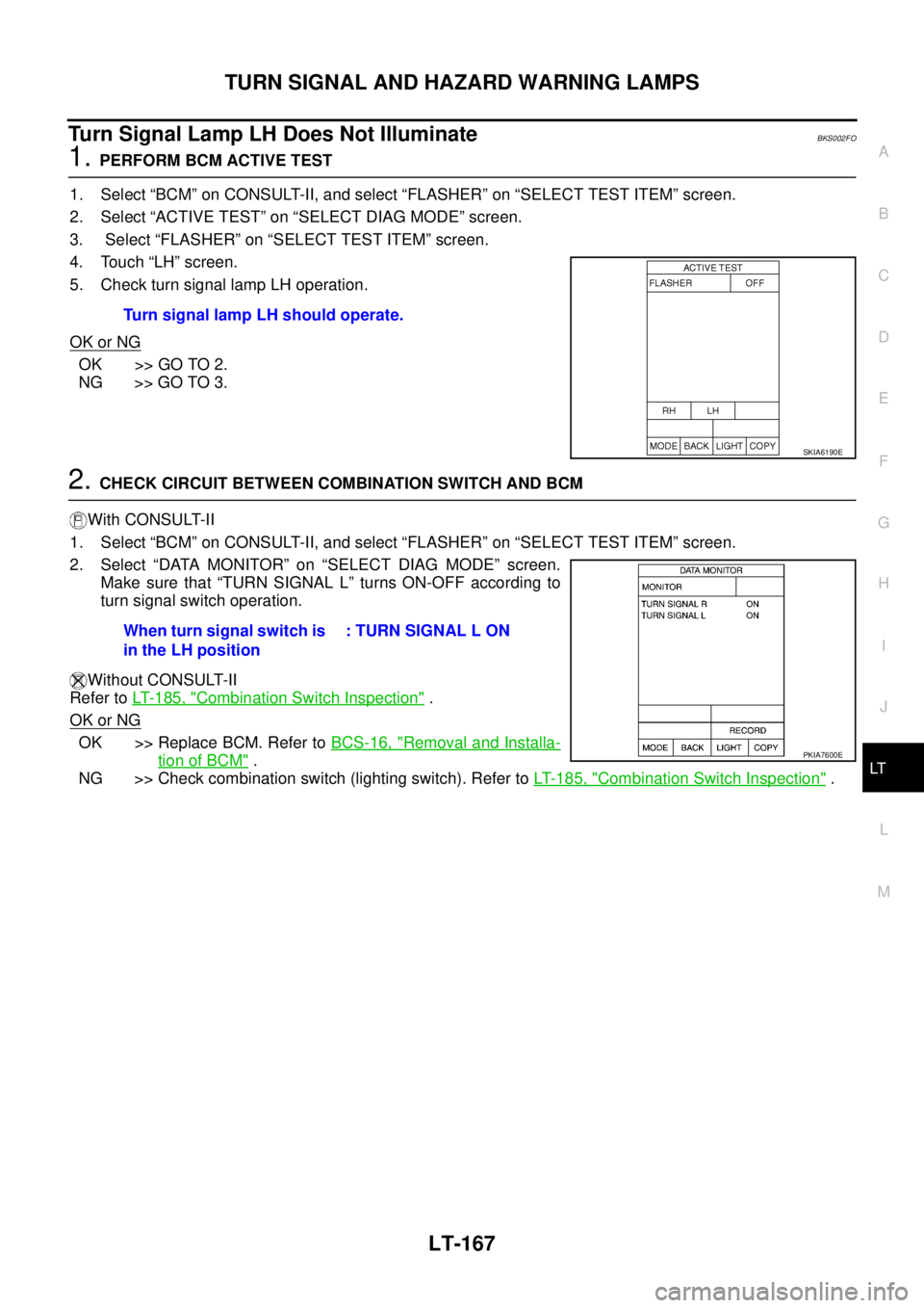
1. Select “BCM” on CONSULT-II, and select “FLASHER” on “SELECT TEST ITEM” screen.
2. Select “ACTIVE TEST” on “SELECT DIAG MODE” screen.
3. Select “FLASHER” on “SELECT TEST ITEM” screen.
4. Touch “LH” screen.
5. Check turn signal lamp LH operation.
OK or NG
OK >> GO TO 2.
NG >> GO TO 3.
2. CHECK CIRCUIT BETWEEN COMBINATION SWITCH AND BCM
With CONSULT-II
1. Select “BCM” on CONSULT-II, and select “FLASHER” on “SELECT TEST ITEM” screen.
2. Select “DATA MONITOR” on “SELECT DIAG MODE” screen.
Make sure that “TURN SIGNAL L” turns ON-OFF according to
turn signal switch operation.
Without CONSULT-II
Refer to LT- 1 8 5 , "
Combination Switch Inspection" .
OK or NG
OK >> Replace BCM. Refer to BCS-16, "Removal and Installa-
tion of BCM" .
NG >> Check combination switch (lighting switch). Refer to LT- 1 8 5 , "
Combination Switch Inspection" . Turn signal lamp LH should operate.
SKIA6190E
When turn signal switch is
in the LH position: TURN SIGNAL L ON
PKIA7600E
Page 2858 of 3502
LT-170
TURN SIGNAL AND HAZARD WARNING LAMPS
5. CHECK CIRCUIT BETWEEN TURN SIGNAL LAMP AND GROUND
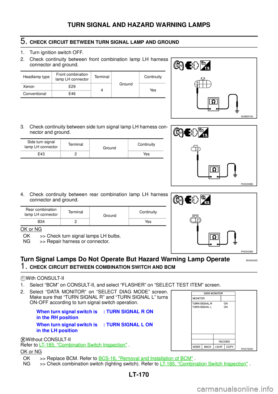
1. Turn ignition switch OFF.
2. Check continuity between front combination lamp LH harness
connector and ground.
3. Check continuity between side turn signal lamp LH harness con-
nector and ground.
4. Check continuity between rear combination lamp LH harness
connector and ground.
OK or NG
OK >> Check turn signal lamps LH bulbs.
NG >> Repair harness or connector.
Turn Signal Lamps Do Not Operate But Hazard Warning Lamp OperateBKS0040D
1. CHECK CIRCUIT BETWEEN COMBINATION SWITCH AND BCM
With CONSULT-II
1. Select “BCM” on CONSULT-II, and select “FLASHER” on “SELECT TEST ITEM” screen.
2. Select “DATA MONITOR” on “SELECT DIAG MODE” screen.
Make sure that “TURN SIGNAL R” and “TURN SIGNAL L” turns
ON-OFF according to turn signal switch operation.
Without CONSULT-II
Refer to LT- 1 8 5 , "
Combination Switch Inspection" .
OK or NG
OK >> Replace BCM. Refer to BCS-16, "Removal and Installation of BCM" .
NG >> Check combination switch (lighting switch). Refer to LT- 1 8 5 , "
Combination Switch Inspection" .
Headlamp typeFront combination
lamp LH connectorTerminal
GroundContinuity
Xenon E29
4Yes
Conventional E46
SKIB8819E
Side turn signal
lamp LH connectorTerminal
GroundContinuity
E43 2 Yes
PKID0098E
Rear combination
lamp LH connectorTerminal
GroundContinuity
B34 2 Yes
PKID0099E
When turn signal switch is
in the RH position: TURN SIGNAL R ON
When turn signal switch is
in the LH position: TURN SIGNAL L ON
PKIA7600E
Page 2862 of 3502
LT-174
TURN SIGNAL AND HAZARD WARNING LAMPS
2. CHECK CIRCUIT BETWEEN COMBINATION SWITCH AND BCM
With CONSULT-II
1. Select “BCM” on CONSULT-II, and select “FLASHER” on “SELECT TEST ITEM” screen.
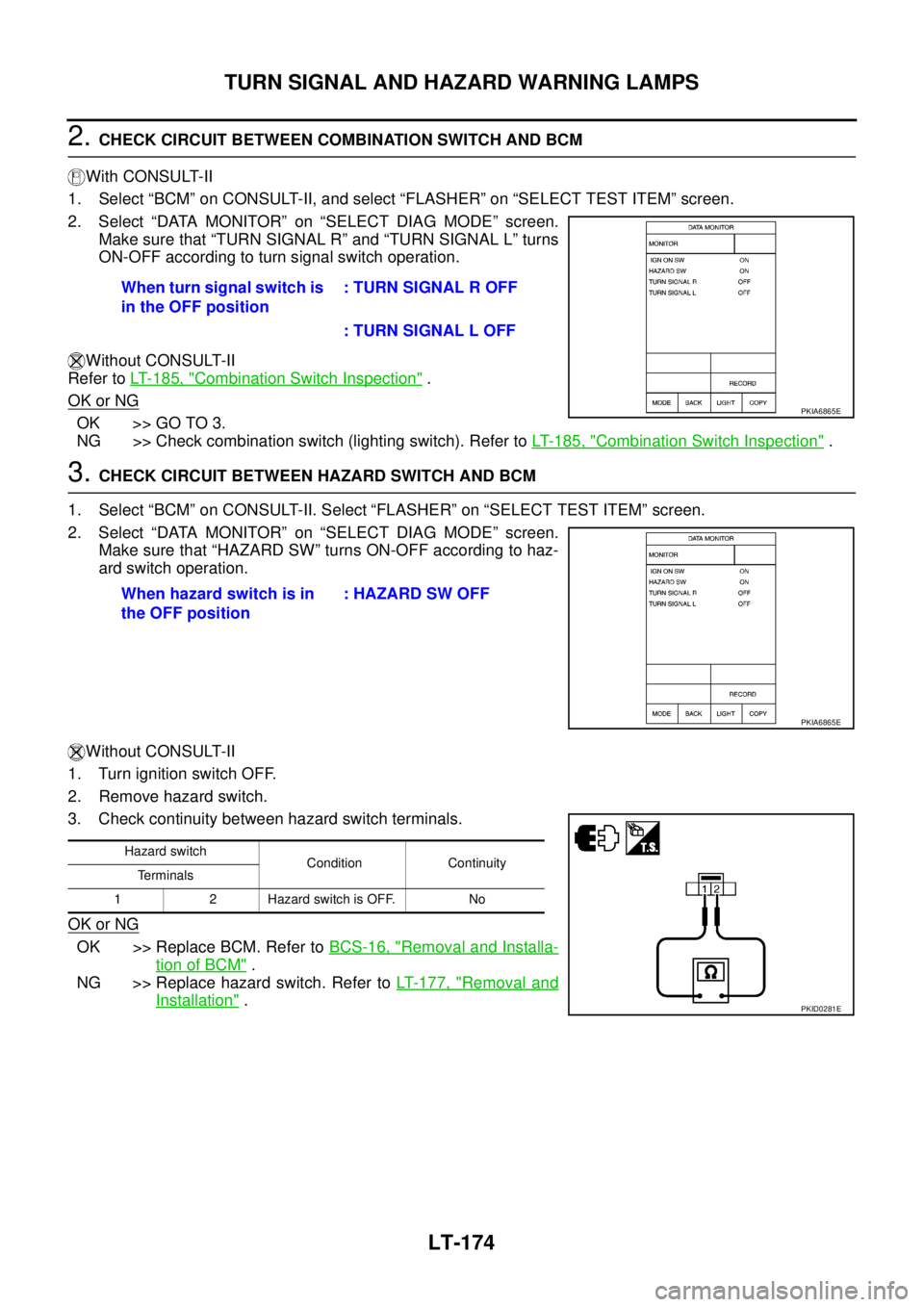
2. Select “DATA MONITOR” on “SELECT DIAG MODE” screen.
Make sure that “TURN SIGNAL R” and “TURN SIGNAL L” turns
ON-OFF according to turn signal switch operation.
Without CONSULT-II
Refer to LT- 1 8 5 , "
Combination Switch Inspection" .
OK or NG
OK >> GO TO 3.
NG >> Check combination switch (lighting switch). Refer to LT- 1 8 5 , "
Combination Switch Inspection" .
3. CHECK CIRCUIT BETWEEN HAZARD SWITCH AND BCM
1. Select “BCM” on CONSULT-II. Select “FLASHER” on “SELECT TEST ITEM” screen.
2. Select “DATA MONITOR” on “SELECT DIAG MODE” screen.
Make sure that “HAZARD SW” turns ON-OFF according to haz-
ard switch operation.
Without CONSULT-II
1. Turn ignition switch OFF.
2. Remove hazard switch.
3. Check continuity between hazard switch terminals.
OK or NG
OK >> Replace BCM. Refer to BCS-16, "Removal and Installa-
tion of BCM" .
NG >> Replace hazard switch. Refer to LT- 1 7 7 , "
Removal and
Installation" . When turn signal switch is
in the OFF position: TURN SIGNAL R OFF
: TURN SIGNAL L OFF
PKIA6865E
When hazard switch is in
the OFF position : HAZARD SW OFF
PKIA6865E
Hazard switch
Condition Continuity
Terminals
1 2 Hazard switch is OFF. No
PKID0281E
Page 2864 of 3502
LT-176
LIGHTING AND TURN SIGNAL SWITCH
LIGHTING AND TURN SIGNAL SWITCHPFP:25540
Removal and InstallationBKS001Q4
REMOVAL
1. Remove steering column cover. Refer to IP-10, "INSTRUMENT
PANEL ASSEMBLY" .
2. While pressing pawls in direction as shown in the figure, pull
lighting and turn signal switch toward driver door and disconnect
from the base.
INSTALLATION
Installation is the reverse order of removal.
Switch Circuit InspectionBKS001Q5
Refer to LT- 1 8 5 , "Combination Switch Inspection" .
SKIB0899E
Page 2867 of 3502
COMBINATION SWITCH
LT-179
C
D
E
F
G
H
I
J
L
MA
B
LT
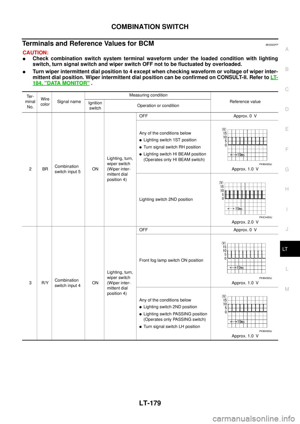
Terminals and Reference Values for BCMBKS002FP
CAUTION:
�Check combination switch system terminal waveform under the loaded condition with lighting
switch, turn signal switch and wiper switch OFF not to be fluctuated by overloaded.
�Turn wiper intermittent dial position to 4 except when checking waveform or voltage of wiper inter-
mittent dial position. Wiper intermittent dial position can be confirmed on CONSULT-II. Refer to LT-
184, "DATA MONITOR" .
Te r -
minal
No.Wire
colorSignal nameMeasuring condition
Reference value
Ignition
switchOperation or condition
2BRCombination
switch input 5ONLighting, turn,
wiper switch
(Wiper inter-
mittent dial
position 4)OFF Approx. 0 V
Any of the conditions below
�Lighting switch 1ST position
�Turn signal switch RH position
�Lighting switch HI BEAM position
(Operates only HI BEAM switch)
Approx. 1.0 V
Lighting switch 2ND position
Approx. 2.0 V
3R/YCombination
switch input 4ONLighting, turn,
wiper switch
(Wiper inter-
mittent dial
position 4)OFF Approx. 0 V
Front fog lamp switch ON position
Approx. 1.0 V
Any of the conditions below
�Lighting switch 2ND position
�Lighting switch PASSING position
(Operates only PASSING switch)
�Turn signal switch LH position
Approx. 1.0 V
PKIB4959J
PKIC4459J
PKIB4955J
PKIB4959J
Page 2868 of 3502
LT-180
COMBINATION SWITCH
4RCombination
switch input 3ONLighting, turn,
wiper switch
(Wiper inter-
mittent dial
position 4)OFF Approx. 0 V
Rear fog switch ON position
Approx. 1.0 V
Any of the conditions below
�Lighting switch AUTO position
�Front wiper switch MIST position
�Front wiper switch INT position
�Front wiper switch LO position
Approx. 1.0 V
5Y/BCombination
switch input 2ONLighting, turn,
wiper switchOFF
(Wiper intermittent dial position 4)Approx. 0 V
Any of the conditions below
�Front washer switch ON position
(Wiper intermittent dial position 4)
�Wiper intermittent dial position 1
�Wiper intermittent dial position 5
�Wiper intermittent dial position 6
Approx. 1.0 V Te r -
minal
No.Wire
colorSignal nameMeasuring condition
Reference value
Ignition
switchOperation or condition
PKIB4955J
PKIB4959J
PKIB4959J
Page 2869 of 3502
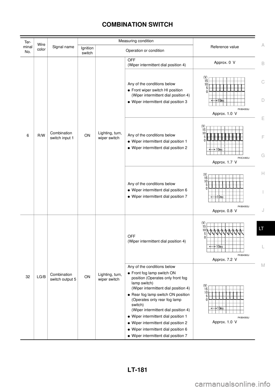
COMBINATION SWITCH
LT-181
C
D
E
F
G
H
I
J
L
MA
B
LT
6R/WCombination
switch input 1ONLighting, turn,
wiper switchOFF
(Wiper intermittent dial position 4)Approx. 0 V
Any of the conditions below
�Front wiper switch HI position
(Wiper intermittent dial position 4)
�Wiper intermittent dial position 3
Approx. 1.0 V
Any of the conditions below
�Wiper intermittent dial position 1
�Wiper intermittent dial position 2
Approx. 1.7 V
Any of the conditions below
�Wiper intermittent dial position 6
�Wiper intermittent dial position 7
Approx. 0.8 V
32 LG/BCombination
switch output 5ONLighting, turn,
wiper switchOFF
(Wiper intermittent dial position 4)
Approx. 7.2 V
Any of the conditions below
�Front fog lamp switch ON
position (Operates only front fog
lamp switch)
(Wiper intermittent dial position 4)
�Rear fog lamp switch ON position
(Operates only rear fog lamp
switch)
(Wiper intermittent dial position 4)
�Wiper intermittent dial position 1
�Wiper intermittent dial position 2
�Wiper intermittent dial position 6
�Wiper intermittent dial position 7Approx. 1.0 V Te r -
minal
No.Wire
colorSignal nameMeasuring condition
Reference value
Ignition
switchOperation or condition
PKIB4959J
PKIC4460J
PKIB4955J
PKIB4960J
PKIB4956J
Page 2870 of 3502
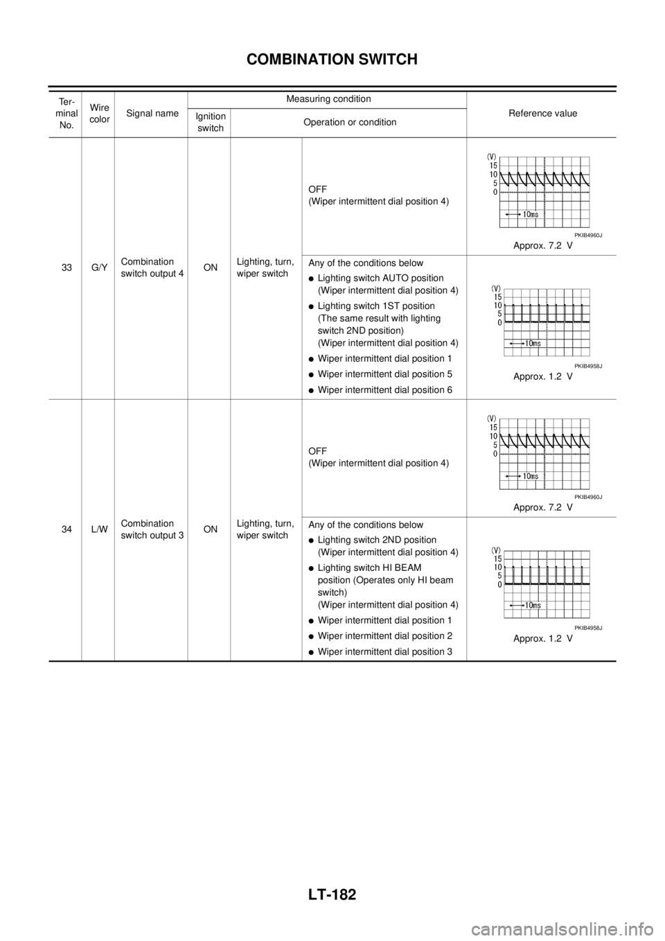
LT-182
COMBINATION SWITCH
33 G/YCombination
switch output 4ONLighting, turn,
wiper switchOFF
(Wiper intermittent dial position 4)
Approx. 7.2 V
Any of the conditions below�Lighting switch AUTO position
(Wiper intermittent dial position 4)
�Lighting switch 1ST position
(The same result with lighting
switch 2ND position)
(Wiper intermittent dial position 4)
�Wiper intermittent dial position 1
�Wiper intermittent dial position 5
�Wiper intermittent dial position 6Approx. 1.2 V
34 L/WCombination
switch output 3ONLighting, turn,
wiper switchOFF
(Wiper intermittent dial position 4)
Approx. 7.2 V
Any of the conditions below
�Lighting switch 2ND position
(Wiper intermittent dial position 4)
�Lighting switch HI BEAM
position (Operates only HI beam
switch)
(Wiper intermittent dial position 4)
�Wiper intermittent dial position 1
�Wiper intermittent dial position 2
�Wiper intermittent dial position 3Approx. 1.2 V Te r -
minal
No.Wire
colorSignal nameMeasuring condition
Reference value
Ignition
switchOperation or condition
PKIB4960J
PKIB4958J
PKIB4960J
PKIB4958J