Page 3455 of 3502

FRONT WIPER AND WASHER SYSTEM
WW-17
C
D
E
F
G
H
I
J
L
MA
B
WW
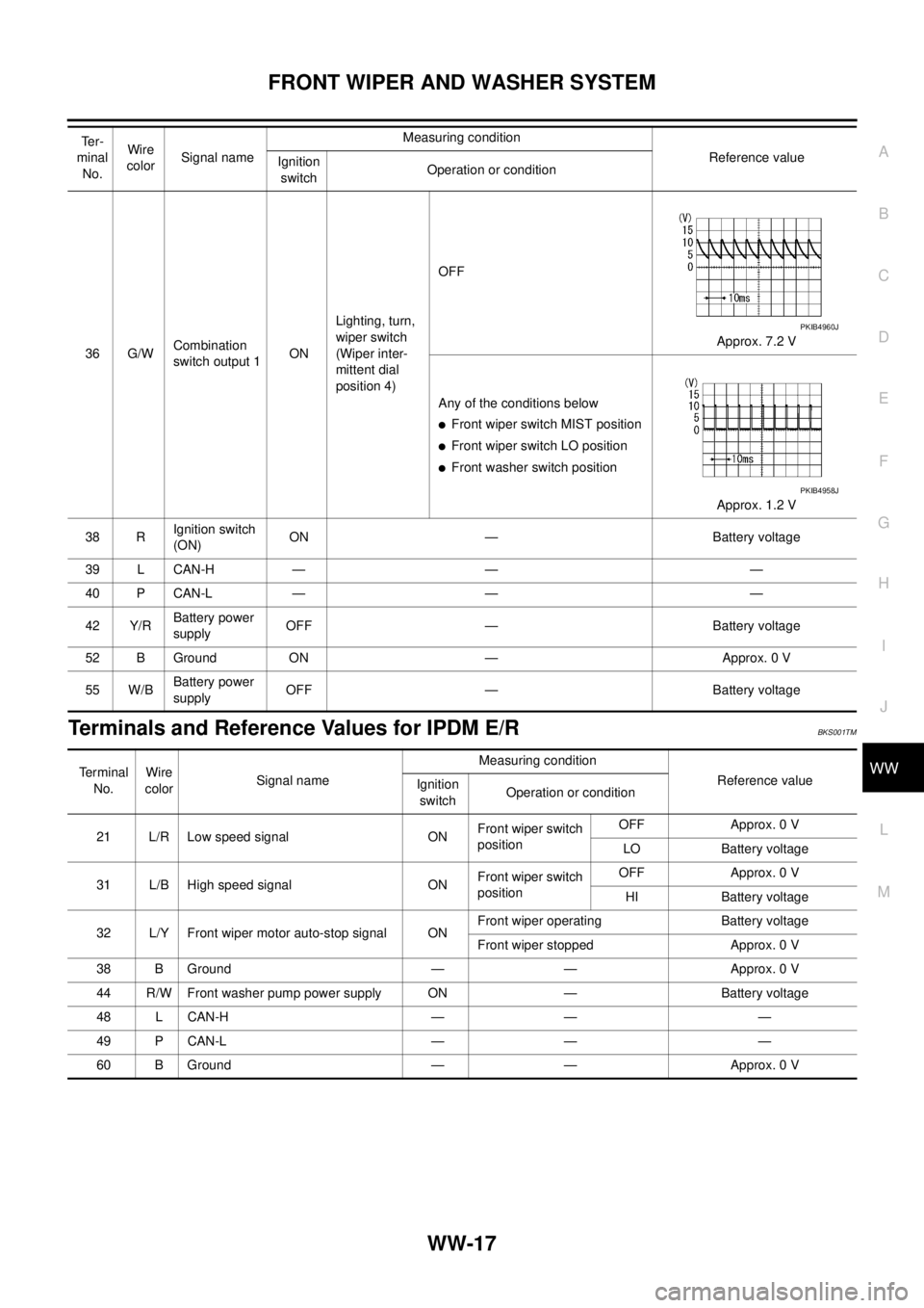
Terminals and Reference Values for IPDM E/RBKS001TM
36 G/WCombination
switch output 1ONLighting, turn,
wiper switch
(Wiper inter-
mittent dial
position 4)OFF
Approx. 7.2 V
Any of the conditions below
�Front wiper switch MIST position
�Front wiper switch LO position
�Front washer switch position
Approx. 1.2 V
38 RIgnition switch
(ON)ON — Battery voltage
39 L CAN-H — — —
40 P CAN-L — — —
42 Y/RBattery power
supplyOFF — Battery voltage
52 B Ground ON — Approx. 0 V
55 W/BBattery power
supplyOFF — Battery voltage Te r -
minal
No.Wire
colorSignal nameMeasuring condition
Reference value
Ignition
switchOperation or condition
PKIB4960J
PKIB4958J
Te r m i n a l
No.Wire
colorSignal nameMeasuring condition
Reference value
Ignition
switchOperation or condition
21 L/R Low speed signal ONFront wiper switch
positionOFF Approx. 0 V
LO Battery voltage
31 L/B High speed signal ONFront wiper switch
positionOFF Approx. 0 V
HI Battery voltage
32 L/Y Front wiper motor auto-stop signal ONFront wiper operating Battery voltage
Front wiper stopped Approx. 0 V
38 B Ground — — Approx. 0 V
44 R/W Front washer pump power supply ON — Battery voltage
48 L CAN-H — — —
49 P CAN-L — — —
60 B Ground — — Approx. 0 V
Page 3479 of 3502

HEADLAMP WASHER
WW-41
C
D
E
F
G
H
I
J
L
MA
B
WW
When the headlamp washer switch is ON, ground is supplied
�to BCM terminal 10
�through headlamp washer switch terminal 1
�through headlamp washer switch terminal 2
�through grounds M71 and M72.
HEADLAMP WASHER OPERATION
When the headlamp washer switch is in ON position with the ignition switch in ON position and the lighting
switch in 2ND position, BCM detects the headlamp washer switch ON signal. It also detects the HEAD LAMP1
and 2 (ON) by BCM combination switch reading function. BCM judges that the condition of headlamp washer
operation meets. And then, BCM sends headlamp washer request signal (ON) through CAN communication.
When receiving headlamp washer request signal (ON), IPDM E/R turns ON headlamp washer relay. And then,
headlamp washer pump operates.
Power is supplied
�through headlamp washer relay terminal 2
�to IPDM E/R terminal 58,
�through headlamp washer relay terminal 5
�to headlamp washer pump terminal 1.
Ground is supplied
�to headlamp washer pump terminal 2
�through grounds E1 and E31.
With power and ground supplied, headlamp washer operates.
INTERLOCKED OPERATION WITH FRONT WINDOW WASHER
When the front window washer switch is in ON position at the every first time of ignition switch ON, with the
ignition switch in ON position and the lighting switch in 2ND position, BCM detects the FR WASHER (ON) and
the HEAD LAMP 1 and 2 (ON) by BCM combination switch reading function. BCM judges that the condition of
headlamp washer operation meets. And then, BCM sends headlamp washer request signal (ON) through
CAN communication.
When receiving headlamp washer request signal (ON), IPDM E/R turns ON headlamp washer relay. And then,
headlamp washer pump operates.
COMBINATION SWITCH READING FUNCTION
Refer to WW-7, "COMBINATION SWITCH READING FUNCTION" .
Page 3484 of 3502

WW-46
HEADLAMP WASHER
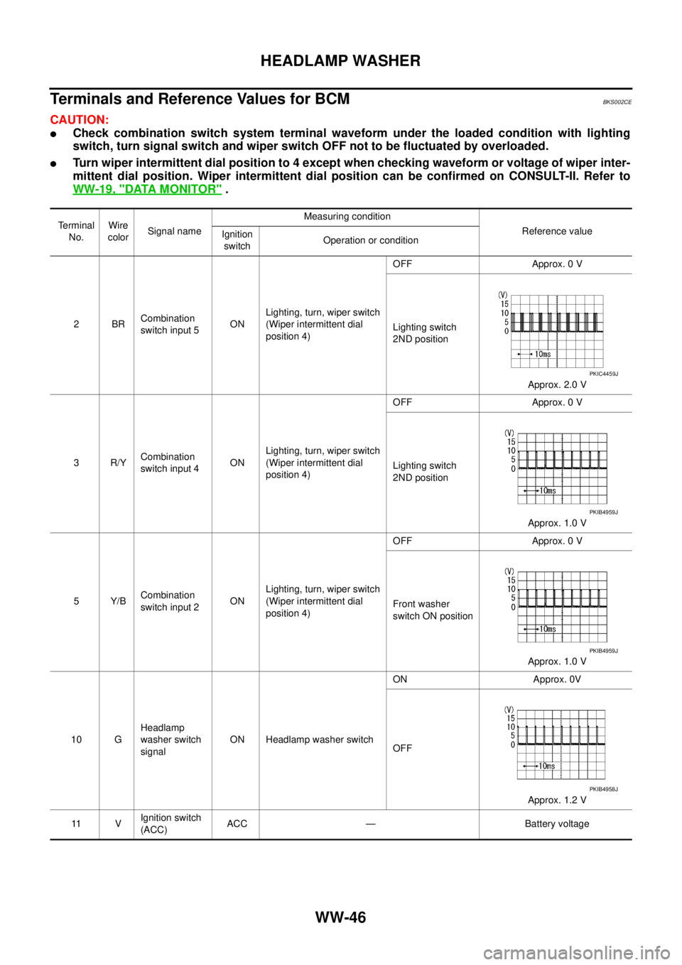
Terminals and Reference Values for BCMBKS002CE
CAUTION:
�Check combination switch system terminal waveform under the loaded condition with lighting
switch, turn signal switch and wiper switch OFF not to be fluctuated by overloaded.
�Turn wiper intermittent dial position to 4 except when checking waveform or voltage of wiper inter-
mittent dial position. Wiper intermittent dial position can be confirmed on CONSULT-II. Refer to
WW-19, "
DATA MONITOR" .
Terminal
No.Wire
colorSignal nameMeasuring condition
Reference value
Ignition
switchOperation or condition
2BRCombination
switch input 5ONLighting, turn, wiper switch
(Wiper intermittent dial
position 4)OFF Approx. 0 V
Lighting switch
2ND position
Approx. 2.0 V
3R/YCombination
switch input 4ONLighting, turn, wiper switch
(Wiper intermittent dial
position 4)OFF Approx. 0 V
Lighting switch
2ND position
Approx. 1.0 V
5Y/BCombination
switch input 2ONLighting, turn, wiper switch
(Wiper intermittent dial
position 4)OFF Approx. 0 V
Front washer
switch ON position
Approx. 1.0 V
10 GHeadlamp
washer switch
signalON Headlamp washer switchON Approx. 0V
OFF
Approx. 1.2 V
11 VIgnition switch
(ACC)ACC — Battery voltage
PKIC4459J
PKIB4959J
PKIB4959J
PKIB4958J
Page 3485 of 3502
HEADLAMP WASHER
WW-47
C
D
E
F
G
H
I
J
L
MA
B
WW
34 L/WCombination
switch output 3ONLighting, turn, wiper switch
(Wiper intermittent dial
position 4)OFF
Approx. 7.2 V
Lighting switch
2ND position
Approx. 1.2 V
35 G/BCombination
switch output 2ONLighting, turn, wiper switch
(Wiper intermittent dial
position 4)OFF
Approx. 7.2 V
Lighting switch
2ND position
Approx. 1.2 V
36 G/WCombination
switch output 1ONLighting, turn, wiper switch
(Wiper intermittent dial
position 4)OFF
Approx. 7.2 V
Front washer
switch ON position
Approx. 1.2 V
38 RIgnition switch
(ON) ON — Battery voltage Te r m i n a l
No.Wire
colorSignal nameMeasuring condition
Reference value
Ignition
switchOperation or condition
PKIB4960J
PKIB4958J
PKIB4960J
PKIB4958J
PKIB4960J
PKIB4958J
Page 3490 of 3502

WW-52
HEADLAMP WASHER
CONSULT-II Functions (IPDM E/R)BKS002CJ
CONSULT-II can display each diagnostic item using the diagnostic test mode shown following.
CONSULT-II BASIC OPERATION
Refer to GI-34, "CONSULT-II Start Procedure" .
DATA MONITOR
Operation Procedure
1. Touch “DATA MONITOR” on “SELECT DIAG MODE ” screen.
2. Touch “ALL SIGNALS”, “MAIN SIGNALS” or “SELECTION FROM MENU” on “SELECT MONITOR ITEM”
screen.
3. When “ALL SIGNALS” is selected, all items will be monitored. When “MAIN SIGNALS” is selected, prede-
termined items will be monitored. When “SELECTION FROM MENU” is selected, touch individual items to
be monitored.
4. Touch “START”.
5. Touch “RECORD” while monitoring to record the status of the item being monitored. To stop recording,
touch “STOP”.
Display Item List
NOTE:
Perform monitoring of IPDM E/R data with ignition switch ON. When ignition switch is at ACC, the display may not be correct.
ACTIVE TEST
Operation Procedure
1. Touch “ACTIVE TEST” on “SELECT DIAG MODE” screen.
2. Touch “HEAD LAMP WASHER” on “SELECT TEST ITEM” screen.
3. Touch “ON” screen.
Diagnosis Mode Description
SELF-DIAGNOSTIC RESULTS Refer to PG-19, "
SELF-DIAG RESULTS" .
DATA MONITOR The input/output data of the IPDM E/R is displayed in real time.
CAN DIAG SUPPORT MNTR The result of transmit/receive diagnosis of CAN communication can be read.
ACTIVE TEST IPDM E/R sends a drive signal to electronic components to check their operation.
ALL SIGNALS Monitors all items.
MAIN SIGNALS Monitor the predetermined item.
SELECTION FROM MENU Select items and monitor them.
Monitor item Contents
HL LO REQ “ON/OFF”Status (lighting switch 2ND position: ON/others: OFF) of lighting switch 2ND position judged
from headlamp low beam request signal through CAN communication is displayed.
HL HI REQ “ON/OFF”Status (high beam or flash-to-passing switch: ON/others: OFF) of high beam or passing switch
judged from headlamp high beam request signal through CAN communication is displayed.
HL WASHER REQ “ON/OFF”Status (headlamp washer switch ON position: ON/others: OFF) of headlamp washer switch
judged from headlamp washer request signal through CAN communication is displayed.
CONSULT-II screen display Test item Description
HEAD LAMP WASHER Headlamp washer operation Headlamp washer relay is operated by switching operation ON-OFF.
Page 3498 of 3502
WW-60
CIGARETTE LIGHTER
CIGARETTE LIGHTERPFP:35330
Wiring Diagram — CIGAR —BKS001UB
TKWM2321E
Page 3499 of 3502
CIGARETTE LIGHTER
WW-61
C
D
E
F
G
H
I
J
L
MA
B
WW
Removal and InstallationBKS001UC
REMOVAL
1. Remove ashtray. Refer to IP-10, "INSTRUMENT PANEL ASSEMBLY" .
2. Remove screws from rearward cigarette lighter socket.
3. Pull out cigarette lighter.
4. Insert a small screwdriver or similar tool between the cigarette
lighter socket and cigarette lighter ring. Pull out cigarette lighter
socket.
INSTALLATION
Installation is the reverse order of removal.
CAUTION:
Align notches of cigarette lighter ring and cigarette lighter socket when installing.
SKIA6400E
SKIA6401E