Page 246 of 3502

AT-238
AIR BREATHER HOSE
REMOVAL AND INSTALLATION (QR20DE ENGINE MODELS)
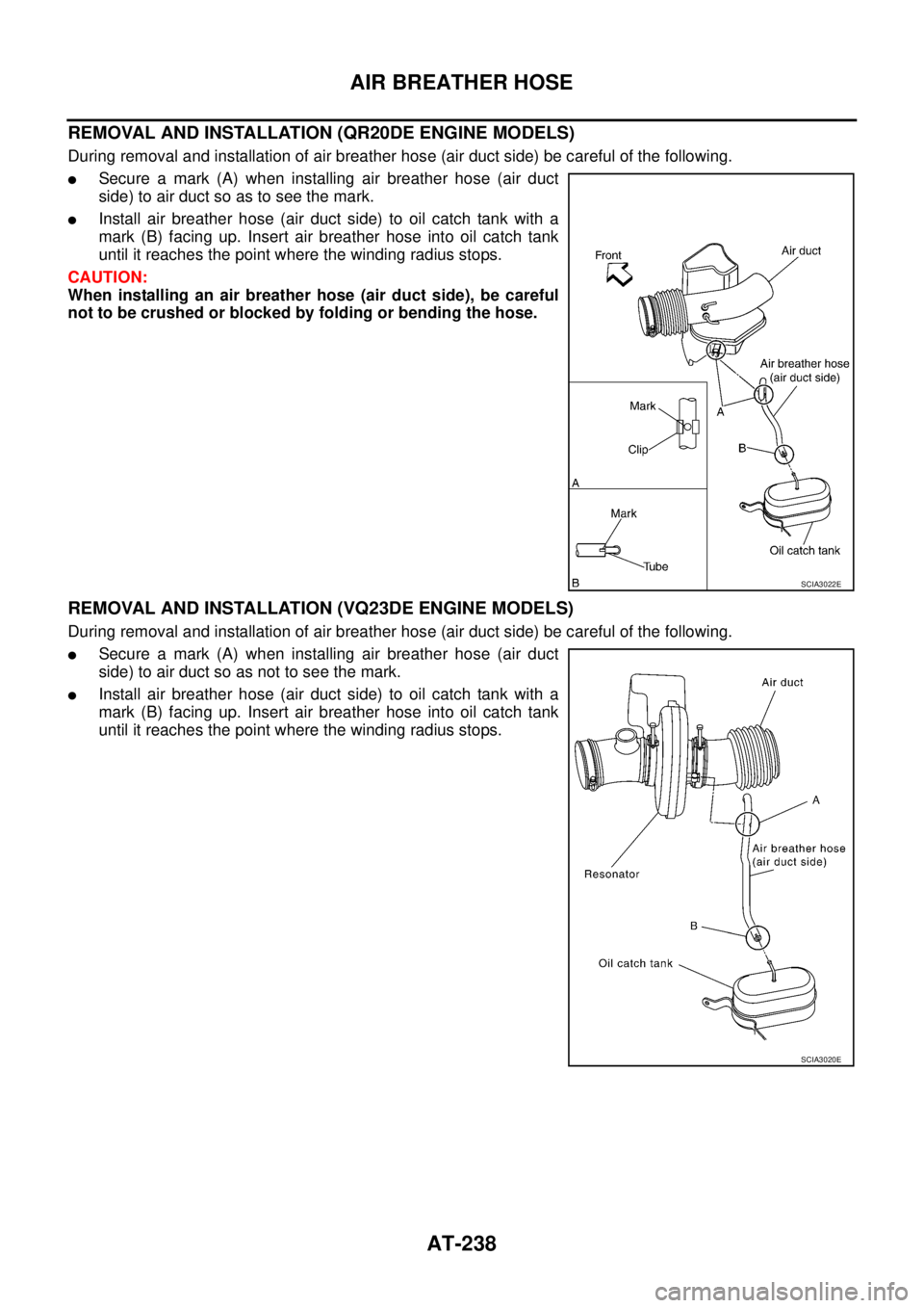
During removal and installation of air breather hose (air duct side) be careful of the following.
�Secure a mark (A) when installing air breather hose (air duct
side) to air duct so as to see the mark.
�Install air breather hose (air duct side) to oil catch tank with a
mark (B) facing up. Insert air breather hose into oil catch tank
until it reaches the point where the winding radius stops.
CAUTION:
When installing an air breather hose (air duct side), be careful
not to be crushed or blocked by folding or bending the hose.
REMOVAL AND INSTALLATION (VQ23DE ENGINE MODELS)
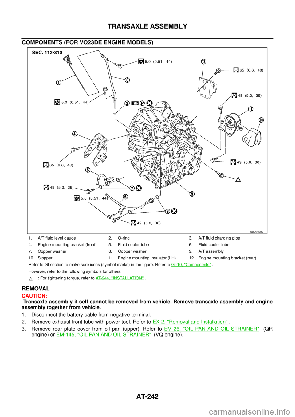
During removal and installation of air breather hose (air duct side) be careful of the following.
�Secure a mark (A) when installing air breather hose (air duct
side) to air duct so as not to see the mark.
�Install air breather hose (air duct side) to oil catch tank with a
mark (B) facing up. Insert air breather hose into oil catch tank
until it reaches the point where the winding radius stops.
SCIA3022E
SCIA3020E
Page 250 of 3502

AT-242
TRANSAXLE ASSEMBLY
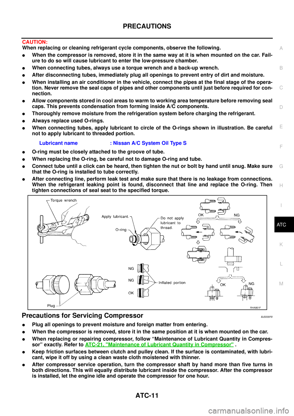
COMPONENTS (FOR VQ23DE ENGINE MODELS)
REMOVAL
CAUTION:
Transaxle assembly it self cannot be removed from vehicle. Remove transaxle assembly and engine
assembly together from vehicle.
1. Disconnect the battery cable from negative terminal.
2. Remove exhaust front tube with power tool. Refer to EX-2, "
Removal and Installation" .
3. Remove rear plate cover from oil pan (upper). Refer to EM-26, "
OIL PAN AND OIL STRAINER" (QR
engine) or EM-145, "
OIL PAN AND OIL STRAINER" (VQ engine).
1. A/T fluid level gauge 2. O-ring 3. A/T fluid charging pipe
4. Engine mounting bracket (front) 5. Fluid cooler tube 6. Fluid cooler tube
7. Copper washer 8. Copper washer 9. A/T assembly
10. Stopper 11. Engine mounting insulator (LH) 12. Engine mounting bracket (rear)
Refer to GI section to make sure icons (symbol marks) in the figure. Refer to GI-10, "
Components" .
However, refer to the following symbols for others.
: For tightening torque, refer to AT-244, "
INSTALLATION" .
SCIA7838E
Page 369 of 3502
ASSEMBLY
AT-361
D
E
F
G
H
I
J
K
L
MA
B
AT
b. Install torque converter while aligning notches of torque con-
verter with notches of oil pump.
c. Measure distance “A” to Make sure that torque converter is in
proper position.
SAT429D
Distance “A”
For QR20DE engine models:
19 mm (0.75 in) or more
For VQ23DE engine models:
14 mm (0.55 in) or more
SAT430D
Page 372 of 3502

AT-364
SERVICE DATA AND SPECIFICATIONS (SDS)
OUTER DIAMETER OF SNAP RINGS
Unit: mm (in)
Control ValvesBCS001P2
CONTROL VALVE RETURN SPRINGS
For QR20DE Engine Models
Unit: mm (in) Location Outer diameter
1 144.8 (5.701)
2 173.8 (6.843)
3 133.9 (5.272)
4 119.1 (4.689)
5 150 (5.91)
6 182.8 (7.197)
PartsItem
Free length Outer diameter
Upper bodyL14 Pilot valve spring 38.98 (1.535) 8.9 (0.350)
L151-2 accumulator valve spring 20.5 (0.807) 6.95 (0.274)
1-2 accumulator piston spring 55.66 (2.191) 19.6 (0.772)
L16 1st reducing valve spring 27.0 (1.062) 7.0 (0.276)
L17 3-2 timing valve spring 23.0 (0.906) 6.65 (0.262)
L18 Overrun clutch reducing valve spring 37.5 (1.476) 6.9 (0.272)
L19 Torque converter relief valve spring 31.0 (1.220) 9.0 (0.354)
L20 Torque converter clutch control valve spring 56.98 (2.243) 6.5 (0.256)
L21 Cooler check valve spring 29.4 (1.157) 6.0 (0.236)
Lower bodyL3 Pressure regulator valve spring 45.0 (1.772) 15.0 (0.591)
L4 Overrun clutch control valve spring 21.7 (0.854) 7.0 (0.276)
L5 Accumulator control valve spring 22.0 (0.866) 6.5 (0.256)
L6 Shift valve A spring 21.7 (0.854) 7.0 (0.276)
L7 Shuttle valve spring 51.0 (2.008) 5.65 (0.222)
L12 Shift valve B spring 21.7 (0.854) 7.0 (0.276)
L13Pressure modifier valve spring 32.0 (1.260) 6.9 (0.272)
Pressure modifier piston spring 30.5 (1.201) 9.8 (0.386)
— Oil cooler relief valve spring 17.02 (0.670) 8.0 (0.315)
Page 373 of 3502

SERVICE DATA AND SPECIFICATIONS (SDS)
AT-365
D
E
F
G
H
I
J
K
L
MA
B
AT
For VQ23DE Engine Models
Unit: mm (in)
AccumulatorBCS001P3
O-RINGS
Unit: mm (in)
RETURN SPRINGS
Unit: mm (in) PartsItem
Free length Outer diameter
Upper bodyL14 Pilot valve spring 38.98 (1.535) 8.9 (0.350)
L151-2 accumulator valve spring 20.5 (0.807) 6.95 (0.274)
1-2 accumulator piston spring 55.66 (2.191) 19.6 (0.772)
L16 1st reducing valve spring 26.0 (1.024) 7.0 (0.276)
L17 3-2 timing valve spring 23.0 (0.906) 6.65 (0.262)
L18 Overrun clutch reducing valve spring 37.5 (1.476) 6.9 (0.272)
L19 Torque converter relief valve spring 31.0 (1.220) 9.0 (0.354)
L20 Torque converter clutch control valve spring 56.98 (2.243) 6.5 (0.256)
L21 Cooler check valve spring 29.4 (1.157) 6.0 (0.236)
Lower bodyL3 Pressure regulator valve spring 45.0 (1.772) 15.0 (0.591)
L4 Overrun clutch control valve spring 21.7 (0.854) 7.0 (0.276)
L5 Accumulator control valve spring 22.0 (0.866) 6.5 (0.256)
L6 Shift valve A spring 21.7 (0.854) 7.0 (0.276)
L7 Shuttle valve spring 51.0 (2.008) 5.65 (0.222)
L12 Shift valve B spring 21.7 (0.854) 7.0 (0.276)
L13Pressure modifier valve spring 32.0 (1.260) 6.9 (0.272)
Pressure modifier piston spring 30.5 (1.201) 9.8 (0.386)
— Oil cooler relief valve spring 17.02 (0.670) 8.0 (0.315)
AccumulatorInner diameter
(Small)Inner diameter
(Large)
Servo release accumulator 26.9 (1.059) 44.2 (1.740)
N-D accumulator 34.6 (1.362) 39.4 (1.551)
Accumulator Free length Outer diameter
Servo release accumulator 62.8 (2.472) 21.0 (0.827)
N-D accumulator 46.5 (1.831) 28.0 (1.102)
Page 389 of 3502

PRECAUTIONS
ATC-11
C
D
E
F
G
H
I
K
L
MA
B
AT C
CAUTION:
When replacing or cleaning refrigerant cycle components, observe the following.
�When the compressor is removed, store it in the same way at it is when mounted on the car. Fail-
ure to do so will cause lubricant to enter the low-pressure chamber.
�When connecting tubes, always use a torque wrench and a back-up wrench.
�After disconnecting tubes, immediately plug all openings to prevent entry of dirt and moisture.
�When installing an air conditioner in the vehicle, connect the pipes at the final stage of the opera-
tion. Never remove the seal caps of pipes and other components until just before required for con-
nection.
�Allow components stored in cool areas to warm to working area temperature before removing seal
caps. This prevents condensation from forming inside A/C components.
�Thoroughly remove moisture from the refrigeration system before charging the refrigerant.
�Always replace used O-rings.
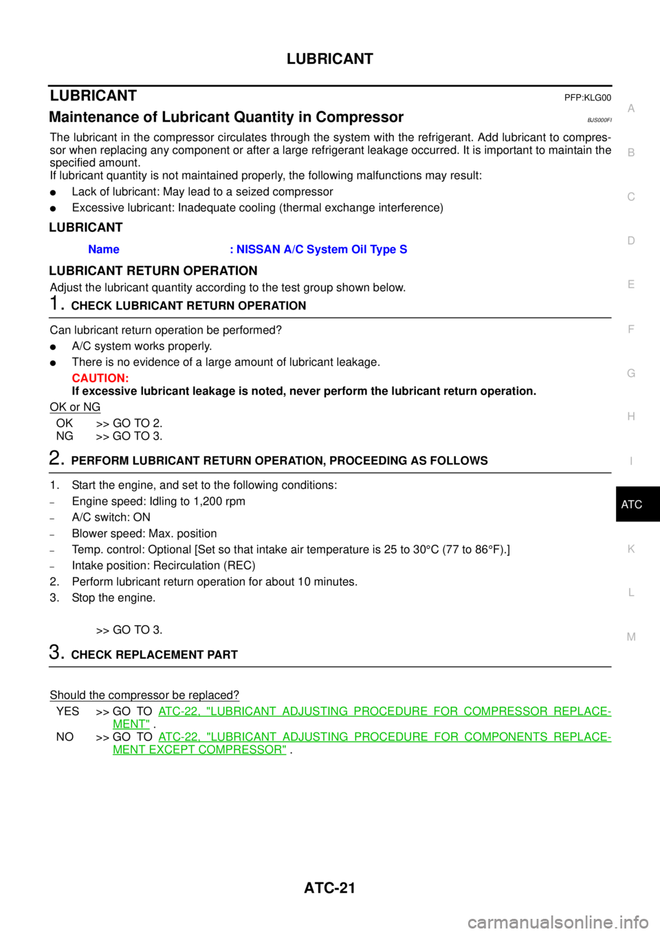
�When connecting tubes, apply lubricant to circle of the O-rings shown in illustration. Be careful
not to apply lubricant to threaded portion.
�O-ring must be closely attached to the groove of tube.
�When replacing the O-ring, be careful not to damage O-ring and tube.
�Connect tube until a click can be heard, then tighten the nut or bolt by hand until snug. Make sure
that the O-ring is installed to tube correctly.
�After connecting line, perform leak test and make sure that there is no leakage from connections.
When the refrigerant leaking point is found, disconnect that line and replace the O-ring. Then
tighten connections of seal seat to the specified torque.
Precautions for Servicing CompressorBJS000F8
�Plug all openings to prevent moisture and foreign matter from entering.
�When the compressor is removed, store it in the same position at it is when mounted on the car.
�When replacing or repairing compressor, follow “Maintenance of Lubricant Quantity in Compres-
sor” exactly. Refer to AT C - 2 1 , "
Maintenance of Lubricant Quantity in Compressor" .
�Keep friction surfaces between clutch and pulley clean. If the surface is contaminated, with lubri-
cant, wipe it off by using a clean waste cloth moistened with thinner.
�After compressor service operation, turn the compressor shaft by hand more than five turns in
both directions. This will equally distribute lubricant inside the compressor. After the compressor
is installed, let the engine idle and operate the compressor for one hour.Lubricant name : Nissan A/C System Oil Type S
RHA861F
Page 399 of 3502

LUBRICANT
ATC-21
C
D
E
F
G
H
I
K
L
MA
B
AT C
LUBRICANTPFP:KLG00
Maintenance of Lubricant Quantity in CompressorBJS000FI
The lubricant in the compressor circulates through the system with the refrigerant. Add lubricant to compres-
sor when replacing any component or after a large refrigerant leakage occurred. It is important to maintain the
specified amount.
If lubricant quantity is not maintained properly, the following malfunctions may result:
�Lack of lubricant: May lead to a seized compressor
�Excessive lubricant: Inadequate cooling (thermal exchange interference)
LUBRICANT
LUBRICANT RETURN OPERATION
Adjust the lubricant quantity according to the test group shown below.
1. CHECK LUBRICANT RETURN OPERATION
Can lubricant return operation be performed?
�A/C system works properly.
�There is no evidence of a large amount of lubricant leakage.
CAUTION:
If excessive lubricant leakage is noted, never perform the lubricant return operation.
OK or NG
OK >> GO TO 2.
NG >> GO TO 3.
2. PERFORM LUBRICANT RETURN OPERATION, PROCEEDING AS FOLLOWS
1. Start the engine, and set to the following conditions:
–Engine speed: Idling to 1,200 rpm
–A/C switch: ON
–Blower speed: Max. position
–Temp. control: Optional [Set so that intake air temperature is 25 to 30°C (77 to 86°F).]
–Intake position: Recirculation (REC)
2. Perform lubricant return operation for about 10 minutes.
3. Stop the engine.
>> GO TO 3.
3. CHECK REPLACEMENT PART
Should the compressor be replaced?
YES >> GO TO AT C - 2 2 , "LUBRICANT ADJUSTING PROCEDURE FOR COMPRESSOR REPLACE-
MENT" .
NO >> GO TO AT C - 2 2 , "
LUBRICANT ADJUSTING PROCEDURE FOR COMPONENTS REPLACE-
MENT EXCEPT COMPRESSOR" . Name : NISSAN A/C System Oil Type S
Page 498 of 3502
ATC-120
HEATER & COOLING UNIT ASSEMBLY
10. Remove mounting bolts from heater & cooling unit.
11. Remove steering column mounting nuts.
12. Remove steering member mounting bolts.
13. Remove steering member, and then remove heater & cooling unit.
INSTALLATION
Installation is basically the reverse order of removal.
CAUTION:
�Replace O-rings of A/C piping with new ones, and then apply compressor oil to it when installing
it.
�Female-side piping connection is thin and easy to deform. Slowly insert the male-side piping
straight in axial direction.
�Insert piping securely until a click is heard.
�After piping connection is completed, pull male-side piping by hand to make sure that connection
does not come loose.
�When recharging refrigerant, check for leaks.
NOTE:
�When filling radiator with coolant, refer to CO-10, "Changing Engine Coolant" (QR engine) or CO-34,
"Changing Engine Coolant" (VQ engine).
�Recharge the refrigerant.
RJIA3303E
RJIA3304E