Page 2757 of 3502

AUTO LIGHT SYSTEM
LT-69
C
D
E
F
G
H
I
J
L
MA
B
LT
Terminals and Reference Values for IPDM E/RBKS001OD
How to Perform Trouble DiagnosisBKS001OE
1. Confirm the symptom or customer complaint.
2. Understand operation description and function description. Refer to LT- 6 4 , "
System Description" .
3. Preform the Preliminary Check. Refer to LT- 7 0 , "
Preliminary Check" .
4. Check symptom and repair or replace the cause of malfunction.
5. Does the auto light system operate normally? If YES, GO TO 6. If NO, GO TO 4.
6. INSPECTION END.
Te r m i n a l
No.Wire
colorSignal nameMeasuring condition
Reference value
Ignition
switchOperation or condition
20 R/Y Headlamp low (RH) ON Lighting switch 2ND positionOFF Approx. 0 V
ON Battery voltage
22 R/LParking, license plate and
tail lampsON Lighting switch 1ST positionOFF Approx. 0 V
ON Battery voltage
27 L/W Headlamp high (RH) ONLighting switch HIGH BEAM
position or PASS positionOFF Approx. 0 V
ON Battery voltage
28 G Headlamp high (LH) ONLighting switch HIGH BEAM
position or PASS positionOFF Approx. 0 V
ON Battery voltage
30 L Headlamp low (LH) ON Lighting switch 2ND positionOFF Approx. 0 V
ON Battery voltage
38 B Ground ON — Approx. 0 V
48 L CAN− H— — —
49 P CAN− L— — —
60 B Ground ON — Approx. 0 V
Page 2758 of 3502

LT-70
AUTO LIGHT SYSTEM
Preliminary CheckBKS001OF
SETTING CHANGE FUNCTIONS
Sensitivity of auto light system can be adjusted using CONSULT-II. Refer to LT- 1 9 , "WORK SUPPORT" .
CHECK POWER SUPPLY AND GROUND CIRCUIT
1. CHECK FUSES AND FUSIBLE LINK
Check for blown fuses and fusible link.
Refer to LT-66, "Wiring Diagram — AUTO/L —" .
OK or NG
OK >> GO TO 2.
NG >> If fuse or fusible link is blown, be sure to eliminate cause of malfunction before installing new fuse
or fusible link. Refer to PG-3, "
POWER SUPPLY ROUTING CIRCUIT" .
2. CHECK POWER SUPPLY CIRCUIT
1. Turn ignition switch OFF.
2. Disconnect BCM connector.
3. Check voltage between BCM harness connector and ground.
OK or NG
OK >> GO TO 3.
NG >> Repair harness or connector.
Unit Power source Fuse and fusible link No.
BCMBatteryM
17
Ignition switch ACC or ON position 6
Ignition switch ON or START position 1
IPDM E/R Battery71
72
74
76
86
Terminal Ignition switch position
(+)
(-) OFF ACC ON
BCM
connectorTerminal
M311
GroundApprox.0 VBattery
voltageBattery
voltage
38 Approx.0 V Approx.0 VBattery
voltage
M442Battery
voltageBattery
voltageBattery
voltage
55Battery
voltageBattery
voltageBattery
voltage
PKIA5204E
Page 2759 of 3502

AUTO LIGHT SYSTEM
LT-71
C
D
E
F
G
H
I
J
L
MA
B
LT
3. CHECK GROUND CIRCUIT
Check continuity between BCM harness connector and ground.
OK or NG
OK >> INSPECTION END
NG >> Repair harness or connector.
CONSULT-II Functions (BCM)BKS001OG
Refer to LT- 1 8 , "CONSULT-II Functions (BCM)"
Auto Light Function Does Not OperateBKS002FX
1. CHECK EXTERIOR LAMPS OPERATION
Check if the following lamps operates normally.
�Headlamp
�Parking lamp
�License plate lamp
�Tail lamp
OK or NG
OK >> GO TO 2.
NG >> Repair or replace malfunctioning parts.
2. CHECK OPTICAL SENSOR OUTPUT SIGNAL
1. Select “BCM” on CONSULT-II, and select “HEAD LAMP” on “SELECT TEST ITEM” screen.
2. Select “DATA MONITOR” on “SELECT DIAG MODE” screen.
On “OPTICAL SENSOR”, check difference in the voltage when
optical sensor is illuminated and not illuminated.
CAUTION:
Optical sensor must be securely subjected to work lamp
light. If the optical sensor is insufficiently illuminated, the
measured value may not satisfy the standard.
OK or NG
OK >> GO TO 3.
NG >> GO TO 5.
BCM connector Terminal
GroundContinuity
M4 52 Yes
PKIA6256E
Illuminated
OPTICAL SENSOR : 3.1 V or more
Not illuminated
OPTICAL SENSOR : 0.6 V or less
PKIA7596E
Page 2760 of 3502

LT-72
AUTO LIGHT SYSTEM
3. PERFORM BCM SELF-DIAGNOSIS
Select “BCM” on CONSULT-II, and perform self-diagnosis for
“BCM”.
Displayed self
-diagnosis results
NO DTC>>GO TO 4.
CAN COMM CIRCUIT>>Refer to LAN-49, "
CAN System Specifica-
tion Chart" .
4. CHECK CIRCUIT BETWEEN COMBINATION SWITCH AND BCM
With CONSULT-II
1. Select “BCM” on CONSULT-II, and select “HEAD LAMP” on “SELECT TEST ITEM” screen.
2. Select “DATA MONITOR” on “SELECT DIAG MODE” screen.
Make sure “AUTO LIGHT SW” turns ON–OFF according to light-
ing switch operation.
Without CONSULT-II
Refer to LT- 1 8 5 , "
Combination Switch Inspection" .
OK or NG
OK >> Replace BCM. Refer to BCS-16, "Removal and Installa-
tion of BCM" .
NG >> Check combination switch (lighting switch). Refer to LT- 1 8 5 , "
Combination Switch Inspection" .
5. CHECK CIRCUIT BETWEEN BCM AND OPTICAL SENSOR
1. Turn ignition switch OFF.
2. Disconnect BCM connector and optical sensor connector.
3. Check continuity between BCM harness connector (A) and opti-
cal sensor harness connector (B).
4. Check continuity between BCM harness connector (A) and
ground.
OK or NG
OK >> GO TO 6.
NG >> Repair harness or connector.
PKIA7627E
When lighting switch is in the
AUTO position: AUTO LIGHT SW ON
PKIA7595E
AB
Continuity
Connector Terminal Connector Terminal
M317
M181
Ye s 14 2
18 3
A
GroundContinuity
Connector Terminal
M317
No 14
18
PKID0277E
Page 2761 of 3502

AUTO LIGHT SYSTEM
LT-73
C
D
E
F
G
H
I
J
L
MA
B
LT
6. CHECK OPTICAL SENSOR OUTPUT VOLTAGE
1. Connect BCM connector and optical sensor connector.
2. Turn ignition switch ON.
3. Check difference in the voltage between BCM and ground, when
optical sensor is illuminated and not illuminated.
CAUTION:
Optical sensor must be securely subjected to work lamp
light. If the optical sensor is insufficiently illuminated, the measured value may not satisfy the
standard.
Check result
OK >> Replace BCM. Refer to BCS-16, "Removal and Installation of BCM" .
NG >> GO TO 7.
7. CHECK BCM OUTPUT VOLTAGE
Check voltage between BCM harness connector and ground.
OK or NG
OK >> GO TO 8.
NG >> Replace BCM. Refer to BCS-16, "
Removal and Installa-
tion of BCM" .
8. CHECK OPTICAL SENSOR GROUND CIRCUIT
Check voltage between BCM harness connector and ground.
OK or NG
OK >> Replace optical sensor.
NG >> Replace BCM. Refer to BCS-16, "
Removal and Installa-
tion of BCM" .
BCM connector Terminal
GroundConditionVoltage
(Approx.)
M3 14When optical sensor
is illuminated.3.1 V or more
When optical sensor
is not illuminated.0.6 V or less
PKID0086E
BCM connector Terminal
GroundVoltage
(Approx.)
M3 17 5 V
PKID0278E
BCM connector Terminal
GroundVoltage
(Approx)
M3 18 0 V
PKID0085E
Page 2762 of 3502
LT-74
AUTO LIGHT SYSTEM
Removal and Installation for Optical SensorBKS001OK
REMOVAL
1. Remove instrument panel. Refer to IP-10, "INSTRUMENT
PANEL ASSEMBLY" .
2. Disconnect optical sensor connector.
3. Remove optical sensor.
INSTALLATION
Installation is the reverse order of removal.
SKIB0895E
Page 2763 of 3502
ACTIVE AFS
LT-75
C
D
E
F
G
H
I
J
L
MA
B
LT
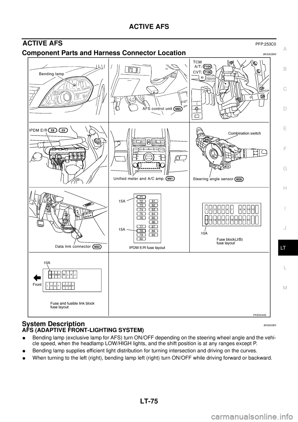
ACTIVE AFSPFP:253C0
Component Parts and Harness Connector LocationBKS002BW
System DescriptionBKS002BX
AFS (ADAPTIVE FRONT-LIGHTING SYSTEM)
�Bending lamp (exclusive lamp for AFS) turn ON/OFF depending on the steering wheel angle and the vehi-
cle speed, when the headlamp LOW/HIGH lights, and the shift position is at any ranges except P.
�Bending lamp supplies efficient light distribution for turning intersection and driving on the curves.
�When turning to the left (right), bending lamp left (right) turn ON/OFF while driving forward or backward.
PKID0044E
Page 2764 of 3502
![NISSAN TEANA 2003 Service Manual LT-76
ACTIVE AFS
OUTLINE
Power is supplied at all times
�to ignition relay [located in IPDM E/R (Intelligent Power Distribution Module Engine Room)], from battery
direct,
�through 15A fuse (No. 71,](/manual-img/5/57392/w960_57392-2763.png "NISSAN TEANA 2003 Service Manual LT-76
ACTIVE AFS
OUTLINE
Power is supplied at all times
�to ignition relay [located in IPDM E/R (Intelligent Power Distribution Module Engine Room)], from battery
direct,
�through 15A fuse (No. 71,")
LT-76
ACTIVE AFS
OUTLINE
Power is supplied at all times
�to ignition relay [located in IPDM E/R (Intelligent Power Distribution Module Engine Room)], from battery
direct,
�through 15A fuse (No. 71, located in IPDM E/R)
�to CPU (central processing unit) in IPDM E/R,
�through 15A fuse (No. 78, located in IPDM E/R)
�to CPU in IPDM E/R,
�through 10A fuse (No. 38, located in fuse and fusible link block)
�to AFS control unit terminal 6.
With the ignition switch in the ON or START position, power is supplied
�to ignition relay (located in IPDM E/R),
�through 10A fuse [No. 12, located in fuse block (J/B)]
�to steering angle sensor terminal 3 and
�to AFS control unit terminal 1.
Ground is supplied
�to IPDM E/R terminals 38 and 60
�through grounds E1 and E31,
�to steering angle sensor terminal 2 and
�to AFS control unit terminal 4
�through grounds M71 and M72.
BENDING LAMP OPERATION
Bending lamp right/left turn ON depending on the steering wheel angle and the vehicle speed under the oper-
ating condition. Bending lamp right/left turn OFF when the steering wheel is returned to the straight.
�Operation condition
�CAN communication control
AFS control unit is connected to CAN communication line, and receives the signal necessary for active
AFS control with CAN communication.
Steering wheel Lighting switch A/T or CVT shift positionBending lamp RH Bending lamp LH
Lamp ON Lamp ON
Turn to rightOFF, 1ST —
2ND
(LOW, HIGH)P range
Except P range×
Turn to leftOFF, 1ST —
2ND
(LOW, HIGH)P range
Except P range×
Ignition switch Headlamp status A/T or CVT shift position Steering wheel angle Vehicle speed
ONIlluminated
(LOW or HIGH)Except P rangeBending lamp turn ON/
OFF according to the
steering wheel angle.Steering wheel angle, which decides if
bending lamp turn ON, depends on the
vehicle speed.
Transmit unit Meter & A/C amp. Steering angle sensor TCM IPDM E/R
Signal name Vehicle speed signal Steering angle sensor signal TCM shift position signal
�Headlamp LO beam signal
�Headlamp HI beam signal