Page 2747 of 3502
HEADLAMP - HALOGEN TYPE -
LT-59
C
D
E
F
G
H
I
J
L
MA
B
LT
Headlamps Low Do Not Go OFF (Both Sides)BKS002FM
1. CHECK IPDM E/R FUNCTION
Make sure that lighting switch is OFF. And make sure low beam headlamp turns off when ignition switch is
turned OFF.
Does low beam headlamp turn OFF?
YES >>LAN-49, "CAN System Specification Chart".
NG >> GO TO 2.
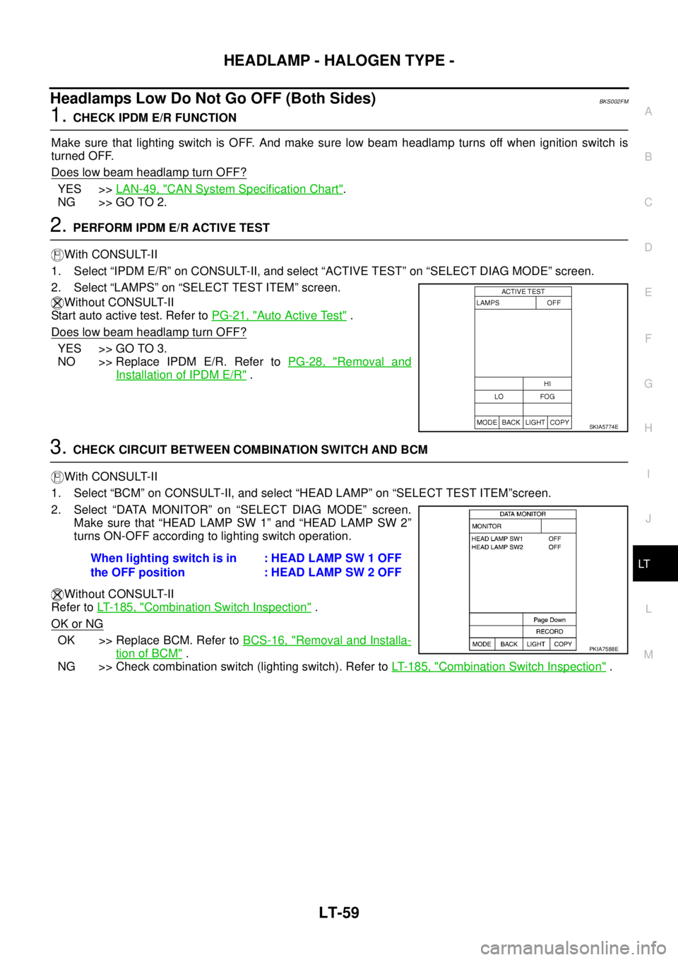
2. PERFORM IPDM E/R ACTIVE TEST
With CONSULT-II
1. Select “IPDM E/R” on CONSULT-II, and select “ACTIVE TEST” on “SELECT DIAG MODE” screen.
2. Select “LAMPS” on “SELECT TEST ITEM” screen.
Without CONSULT-II
Start auto active test. Refer to PG-21, "
Auto Active Test" .
Does low beam headlamp turn OFF?
YES >> GO TO 3.
NO >> Replace IPDM E/R. Refer to PG-28, "
Removal and
Installation of IPDM E/R" .
3. CHECK CIRCUIT BETWEEN COMBINATION SWITCH AND BCM
With CONSULT-II
1. Select “BCM” on CONSULT-II, and select “HEAD LAMP” on “SELECT TEST ITEM”screen.
2. Select “DATA MONITOR” on “SELECT DIAG MODE” screen.
Make sure that “HEAD LAMP SW 1” and “HEAD LAMP SW 2”
turns ON-OFF according to lighting switch operation.
Without CONSULT-II
Refer to LT- 1 8 5 , "
Combination Switch Inspection" .
OK or NG
OK >> Replace BCM. Refer to BCS-16, "Removal and Installa-
tion of BCM" .
NG >> Check combination switch (lighting switch). Refer to LT- 1 8 5 , "
Combination Switch Inspection" .
SKIA5774E
When lighting switch is in
the OFF position: HEAD LAMP SW 1 OFF
: HEAD LAMP SW 2 OFF
PKIA7588E
Page 2749 of 3502
HEADLAMP - HALOGEN TYPE -
LT-61
C
D
E
F
G
H
I
J
L
MA
B
LT
ADJUSTMENT USING AN ADJUSTMENT SCREEN (LIGHT/DARK BORDERLINE)
If the vehicle front body has been repaired and/or the headlamp assembly has been replaced, check aiming.
Use the aiming chart shown in the figure.
�Basic illumination area for adjustment should be within the range shown on the aiming chart.
Adjust headlamp accordingly.
SKIB8856E
Page 2750 of 3502
LT-62
HEADLAMP - HALOGEN TYPE -
Bulb ReplacementBKS001O2
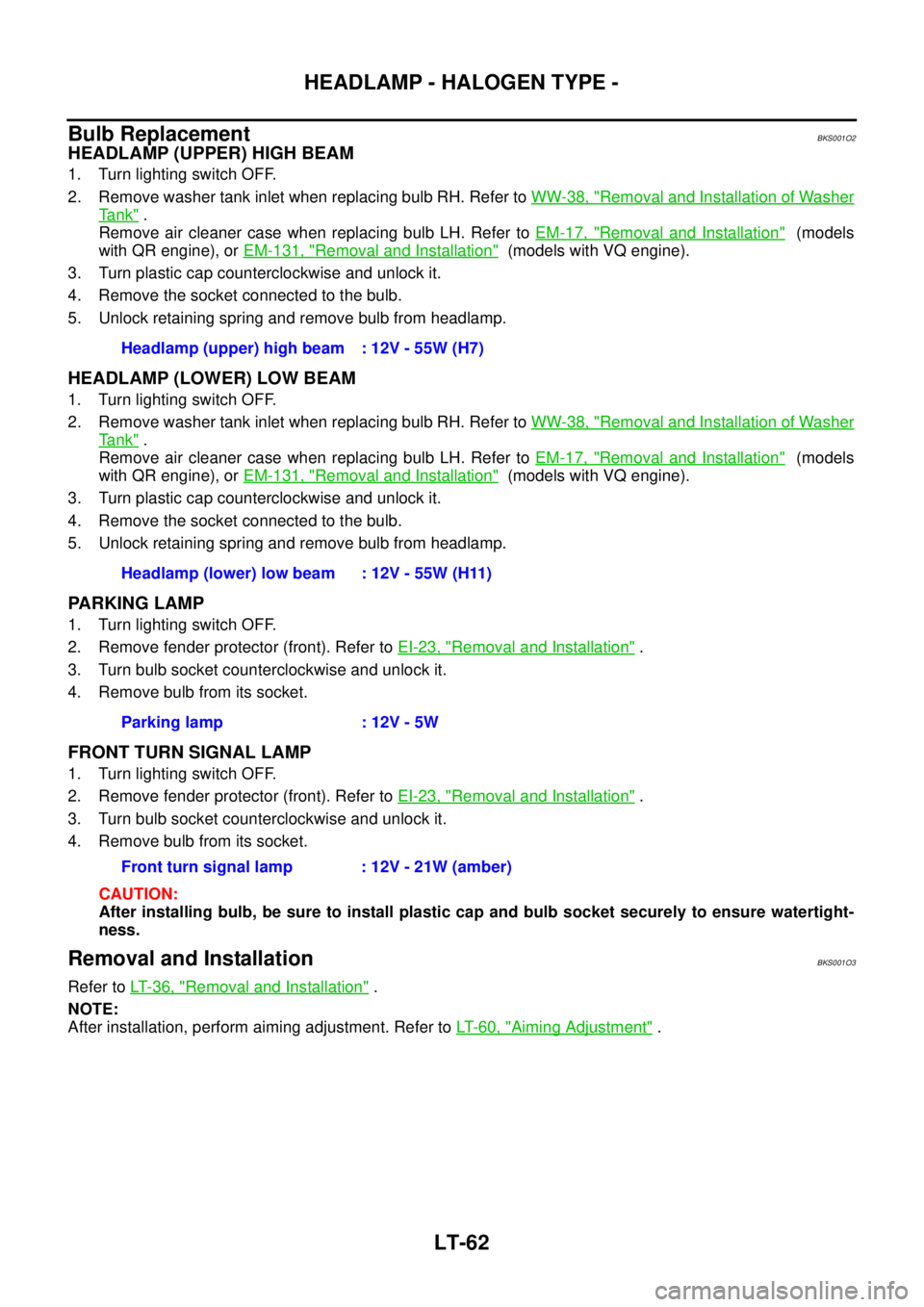
HEADLAMP (UPPER) HIGH BEAM
1. Turn lighting switch OFF.
2. Remove washer tank inlet when replacing bulb RH. Refer to WW-38, "
Removal and Installation of Washer
Ta n k" .
Remove air cleaner case when replacing bulb LH. Refer to EM-17, "
Removal and Installation" (models
with QR engine), or EM-131, "
Removal and Installation" (models with VQ engine).
3. Turn plastic cap counterclockwise and unlock it.
4. Remove the socket connected to the bulb.
5. Unlock retaining spring and remove bulb from headlamp.
HEADLAMP (LOWER) LOW BEAM
1. Turn lighting switch OFF.
2. Remove washer tank inlet when replacing bulb RH. Refer to WW-38, "
Removal and Installation of Washer
Ta n k" .
Remove air cleaner case when replacing bulb LH. Refer to EM-17, "
Removal and Installation" (models
with QR engine), or EM-131, "
Removal and Installation" (models with VQ engine).
3. Turn plastic cap counterclockwise and unlock it.
4. Remove the socket connected to the bulb.
5. Unlock retaining spring and remove bulb from headlamp.
PARKING LAMP
1. Turn lighting switch OFF.
2. Remove fender protector (front). Refer to EI-23, "
Removal and Installation" .
3. Turn bulb socket counterclockwise and unlock it.
4. Remove bulb from its socket.
FRONT TURN SIGNAL LAMP
1. Turn lighting switch OFF.
2. Remove fender protector (front). Refer to EI-23, "
Removal and Installation" .
3. Turn bulb socket counterclockwise and unlock it.
4. Remove bulb from its socket.
CAUTION:
After installing bulb, be sure to install plastic cap and bulb socket securely to ensure watertight-
ness.
Removal and InstallationBKS001O3
Refer to LT- 3 6 , "Removal and Installation" .
NOTE:
After installation, perform aiming adjustment. Refer to LT- 6 0 , "
Aiming Adjustment" . Headlamp (upper) high beam : 12V - 55W (H7)
Headlamp (lower) low beam : 12V - 55W (H11)
Parking lamp : 12V - 5W
Front turn signal lamp : 12V - 21W (amber)
Page 2752 of 3502
LT-64
AUTO LIGHT SYSTEM
AUTO LIGHT SYSTEMPFP:28491
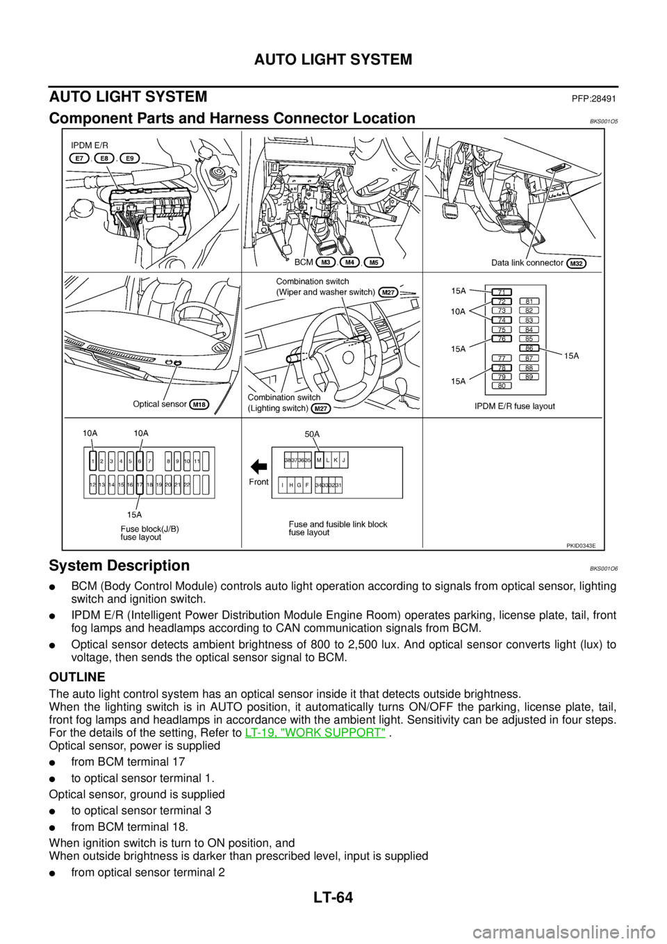
Component Parts and Harness Connector LocationBKS001O5
System DescriptionBKS001O6
�BCM (Body Control Module) controls auto light operation according to signals from optical sensor, lighting
switch and ignition switch.
�IPDM E/R (Intelligent Power Distribution Module Engine Room) operates parking, license plate, tail, front
fog lamps and headlamps according to CAN communication signals from BCM.
�Optical sensor detects ambient brightness of 800 to 2,500 lux. And optical sensor converts light (lux) to
voltage, then sends the optical sensor signal to BCM.
OUTLINE
The auto light control system has an optical sensor inside it that detects outside brightness.
When the lighting switch is in AUTO position, it automatically turns ON/OFF the parking, license plate, tail,
front fog lamps and headlamps in accordance with the ambient light. Sensitivity can be adjusted in four steps.
For the details of the setting, Refer to LT- 1 9 , "
WORK SUPPORT" .
Optical sensor, power is supplied
�from BCM terminal 17
�to optical sensor terminal 1.
Optical sensor, ground is supplied
�to optical sensor terminal 3
�from BCM terminal 18.
When ignition switch is turn to ON position, and
When outside brightness is darker than prescribed level, input is supplied
�from optical sensor terminal 2
PKID0343E
Page 2753 of 3502
AUTO LIGHT SYSTEM
LT-65
C
D
E
F
G
H
I
J
L
MA
B
LT
�to BCM terminal 14.
AUTO LIGHT OPERATION
Applicable lamps
�Low beam headlamp
�Parking, license plate and tail lamps
�High beam headlamp (with the lighting switch in HIGH BEAM position)
�Front fog lamp (with the lighting switch in front fog lamp ON position)
When the lighting switch is in AUTO position with the ignition switch in ON position, BCM detects the AUTO
LIGHT (ON) by BCM combination switch reading function. BCM turns automatically ON/OFF the applicable
lamps according to ambient brightness depending on the following condition.
�It turns ON applicable lamps in 3 seconds when ambient brightness is less than 1250 lux.
�This lighted lamps is turned OFF in 5 seconds when ambient brightness becomes 2500 lux or higher.
Releasing Function:
�Turn ignition switch to the OFF position, or
�Change lighting switch to the OFF, 1ST, 2ND position.
NOTE:
Timing for when lamps turn ON/OFF can be changed by the function setting of CONSULT-II. Refer to LT- 1 9 ,
"WORK SUPPORT" .
COMBINATION SWITCH READING FUNCTION
Refer to BCS-3, "COMBINATION SWITCH READING FUNCTION" .
HEADLAMP LOW AND HIGH OPERATION (XENON TYPE)
Refer to LT- 6 , "System Description" .
HEADLAMP LOW AND HIGH OPERATION (HALOGEN TYPE)
Refer to LT- 3 8 , "System Description" .
FRONT FOG LAMP OPERATION
Refer to LT- 1 2 6 , "System Description" .
PARKING, LICENSE PLATE AND TAIL LAMPS OPERATION
Refer to LT- 1 9 6 , "System Description" .
CAN Communication System DescriptionBKS001O7
CAN (Controller Area Network) is a serial communication line for real time application. It is an on-vehicle mul-
tiplex communication line with high data communication speed and excellent error detection ability. Many elec-
tronic control units are equipped onto a vehicle, and each control unit shares information and links with other
control units during operation (not independent). In CAN communication, control units are connected with 2
communication lines (CAN H line, CAN L line) allowing a high rate of information transmission with less wiring.
Each control unit transmits/receives data but selectively reads required data only.
CAN Communication UnitBKS001O8
Refer to LAN-49, "CAN System Specification Chart" .
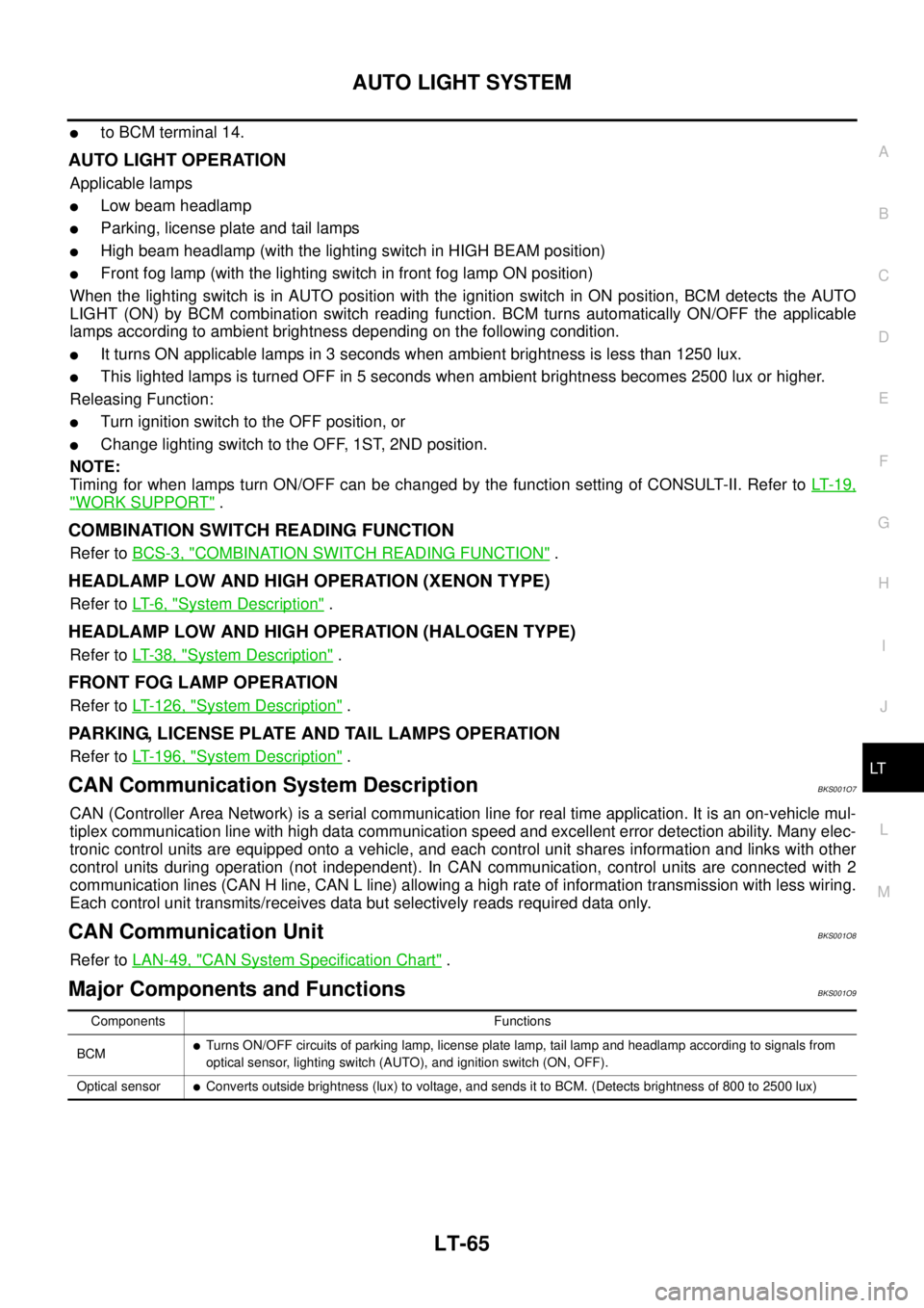
Major Components and FunctionsBKS001O9
Components Functions
BCM
�Turns ON/OFF circuits of parking lamp, license plate lamp, tail lamp and headlamp according to signals from
optical sensor, lighting switch (AUTO), and ignition switch (ON, OFF).
Optical sensor
�Converts outside brightness (lux) to voltage, and sends it to BCM. (Detects brightness of 800 to 2500 lux)
Page 2754 of 3502
LT-66
AUTO LIGHT SYSTEM
Wiring Diagram — AUTO/L —BKS001OB
TKWM4576E
Page 2755 of 3502
AUTO LIGHT SYSTEM
LT-67
C
D
E
F
G
H
I
J
L
MA
B
LT
TKWM4825E
Page 2756 of 3502
LT-68
AUTO LIGHT SYSTEM
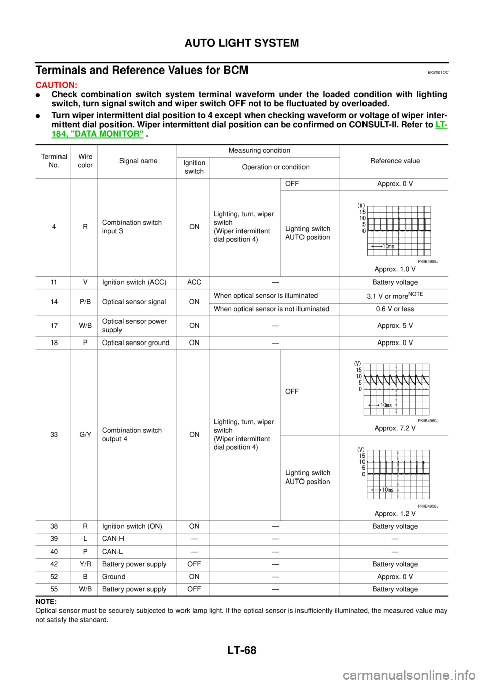
Terminals and Reference Values for BCMBKS001OC
CAUTION:
�Check combination switch system terminal waveform under the loaded condition with lighting
switch, turn signal switch and wiper switch OFF not to be fluctuated by overloaded.
�Turn wiper intermittent dial position to 4 except when checking waveform or voltage of wiper inter-
mittent dial position. Wiper intermittent dial position can be confirmed on CONSULT-II. Refer to LT-
184, "DATA MONITOR" .
NOTE:
Optical sensor must be securely subjected to work lamp light. If the optical sensor is insufficiently illuminated, the measured value may
not satisfy the standard.Terminal
No.Wire
colorSignal nameMeasuring condition
Reference value
Ignition
switchOperation or condition
4RCombination switch
input 3ONLighting, turn, wiper
switch
(Wiper intermittent
dial position 4)OFF Approx. 0 V
Lighting switch
AUTO position
Approx. 1.0 V
11 V Ignition switch (ACC) ACC — Battery voltage
14 P/B Optical sensor signal ONWhen optical sensor is illuminated
3.1 V or more
NOTE
When optical sensor is not illuminated 0.6 V or less
17 W/BOptical sensor power
supplyON — Approx. 5 V
18 P Optical sensor ground ON — Approx. 0 V
33 G/YCombination switch
output 4ONLighting, turn, wiper
switch
(Wiper intermittent
dial position 4)OFF
Approx. 7.2 V
Lighting switch
AUTO position
Approx. 1.2 V
38 R Ignition switch (ON) ON — Battery voltage
39 L CAN-H — — —
40 P CAN-L — — —
42 Y/R Battery power supply OFF — Battery voltage
52 B Ground ON — Approx. 0 V
55 W/B Battery power supply OFF — Battery voltage
PKIB4959J
PKIB4960J
PKIB4958J