Page 17 of 3502
PREPARATION
AT-9
D
E
F
G
H
I
J
K
L
MA
B
AT
PREPARATIONPFP:00100
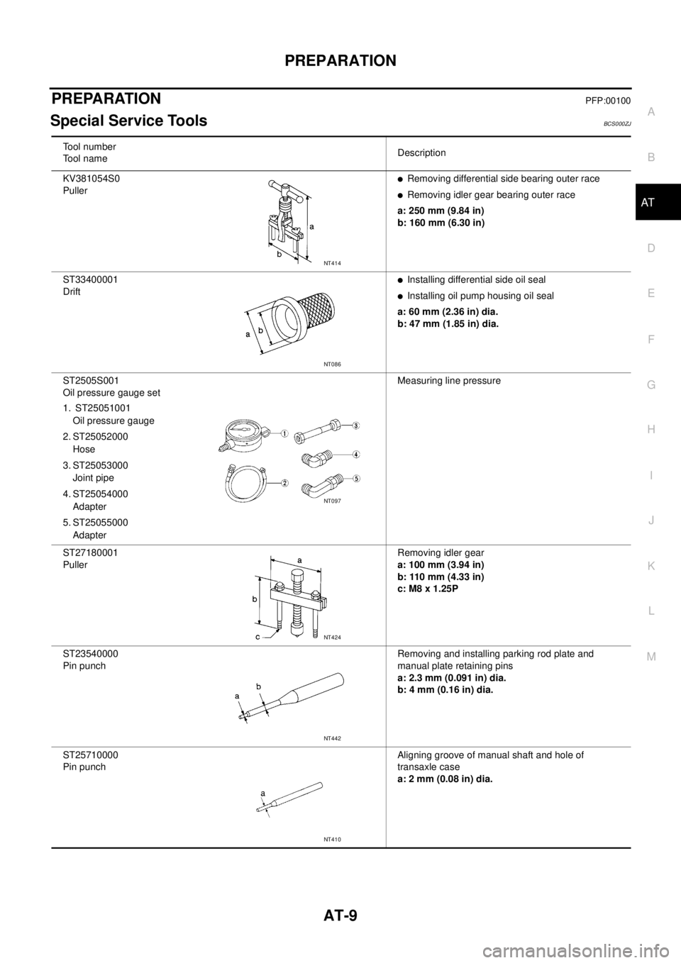
Special Service ToolsBCS000ZJ
Tool number
Tool nameDescription
KV381054S0
Puller
�Removing differential side bearing outer race
�Removing idler gear bearing outer race
a: 250 mm (9.84 in)
b: 160 mm (6.30 in)
ST33400001
Drift
�Installing differential side oil seal
�Installing oil pump housing oil seal
a: 60 mm (2.36 in) dia.
b: 47 mm (1.85 in) dia.
ST2505S001
Oil pressure gauge set
1. ST25051001
Oil pressure gauge
2. ST25052000
Hose
3. ST25053000
Joint pipe
4. ST25054000
Adapter
5. ST25055000
AdapterMeasuring line pressure
ST27180001
PullerRemoving idler gear
a: 100 mm (3.94 in)
b: 110 mm (4.33 in)
c: M8 x 1.25P
ST23540000
Pin punchRemoving and installing parking rod plate and
manual plate retaining pins
a: 2.3 mm (0.091 in) dia.
b: 4 mm (0.16 in) dia.
ST25710000
Pin punchAligning groove of manual shaft and hole of
transaxle case
a: 2 mm (0.08 in) dia.
NT414
NT086
NT097
NT424
NT442
NT410
Page 20 of 3502
AT-12
PREPARATION
Commercial Service Tools BCS000ZK
Tool nameDescription
Power toolLoosening bolts and nuts
PullerRemoving idler gear bearing inner race
PullerRemoving reduction pinion gear bearing inner
race
a: 60 mm (2.36 in) dia.
b: 35 mm (1.38 in) dia.
DriftInstalling radial needle bearing on bearing
retainer
a: 36 mm (1.42 in) dia.
DriftInstalling manual shaft oil seal
a: 22 mm (0.87 in) dia.
DriftRemoving radial needle bearing from bearing
retainer
a: 33.5 mm (1.319 in) dia.
PBIC0190E
NT077
NT411
NT083
NT083
NT083
Page 44 of 3502

AT-36
TROUBLE DIAGNOSIS
How to Perform Trouble Diagnoses for Quick and Accurate RepairBCS000ZZ
INTRODUCTION
The TCM receives a signal from the vehicle speed sensor, accelera-
tor pedal position sensor or PNP switch and provides shift control or
lock-up control via A/T solenoid valves.
Input and output signals must always be correct and stable in the
operation of the A/T system. The A/T system must be in good oper-
ating condition and be free of valve seizure, solenoid valve malfunc-
tion, etc.
It is much more difficult to diagnose a malfunction that occurs inter-
mittently rather than continuously. Most intermittent malfunctions are
caused by poor electric connections or improper wiring. In this case,
careful checking of suspected circuits may help prevent the replace-
ment of good parts.
A visual check only, may not find the cause of the malfunctions. A
road test with CONSULT-II or a circuit tester connected should be
performed. Follow the AT- 3 7 , "
WORK FLOW" .
Before undertaking actual checks, take a few minutes to talk with a
customer who approaches with a drivability complaint. The customer
can supply good information about such malfunctions, especially
intermittent ones. Find out what symptoms are present and under
what conditions they occur. A “DIAGNOSTIC WORKSHEET” like the
example (AT- 3 8 , "
DIAGNOSTIC WORKSHEET" ) should be used.
Start your diagnosis by looking for “conventional” malfunctions first.
This will help troubleshoot drivability malfunctions on an electroni-
cally controlled engine vehicle.
Also check related Service bulletins for information.
SAT631IA
SAT632I
SEF234G
Page 46 of 3502
AT-38
TROUBLE DIAGNOSIS
DIAGNOSTIC WORKSHEET
Information From Customer
KEY POINTS
�WHAT..... Vehicle & A/T models
�WHEN..... Date, Frequencies
�WHERE..... Road conditions
�HOW..... Operating conditions, Symptoms
Customer name MR/MS Model & Year VIN
Trans. model Engine Mileage
Malfunction Date Manuf. Date In Service Date
Frequency❏ Continuous❏ Intermittent ( times a day)
Symptoms❏ Vehicle does not move. (❏ Any position❏ Particular position)
❏ No up-shift (❏ 1st → 2nd❏ 2nd → 3rd❏ 3rd → 4th)
❏ No down-shift (❏ 4th → 3rd❏ 3rd → 2nd❏ 2nd → 1st)
❏ Lock-up malfunction
❏ Shift point too high or too low.
❏ Shift shock or slip (❏ N → D❏ Lock-up❏ Any drive position)
❏ Noise or vibration
❏ No kick down
❏ No pattern select
❏ Others
()
Page 75 of 3502
 BCS0010D
CONSULT-II can display each diagnostic item using the diagnostic test models shown following.
FUNCTION
NOTICE:
1.")
TROUBLE DIAGNOSIS
AT-67
D
E
F
G
H
I
J
K
L
MA
B
AT
CONSULT-II Function (A/T) BCS0010D
CONSULT-II can display each diagnostic item using the diagnostic test models shown following.
FUNCTION
NOTICE:
1. The CONSULT-II electrically displays shift timing and lock-up timing (that is, operation timing of each sole-
noid).
Check for time difference between actual shift timing and the CONSULT-II display. If the difference is
noticeable, mechanical parts (except solenoids, sensors, etc.) may be malfunctioning. Check mechanical
parts using applicable diagnostic procedures.
2. Shift schedule (which implies gear position) displayed on CONSULT-II and that indicated in Service Man-
ual may differ slightly. This occurs because of the following reasons:
–Actual shift schedule has more or less tolerance or allowance,
–Shift schedule indicated in Service Manual refers to the point where shifts start, and
–Gear position displayed on CONSULT-II indicates the point where shifts are completed.
3. Shift solenoid valve “A” or “B” is displayed on CONSULT-II at the start of shifting. Gear position is dis-
played upon completion of shifting (which is computed by TCM).
CONSULT-II REFERENCE VALUE
Diagnostic test mode Function Reference page
Work supportThis mode enables a technician to adjust some devices faster and more accurately by
following the indications on CONSULT-II.—
Self-diagnostic results Self-diagnostic results can be read and erased quickly.AT- 6 9
Data monitor Input/Output data in the ECM can be read.AT- 7 0
CAN diagnostic support
monitorThe results of transmit/receive diagnosis of CAN communication can be read.AT- 7 2
Function testPerformed by CONSULT-II instead of a technician to determine whether each system
is “OK” or “NG”.—
DTC work support Select the operating condition to confirm Diagnosis Trouble Codes.AT- 7 2
TCM part number TCM part number can be read. —
Item name Condition Display value (Approx.)
VHCL/S SE-A/T
During drivingApproximately matches the speedometer
reading.
VHCL/S SE-MTR
THROTTLE POSIReleased accelerator pedal. 0.0/8
Fully depressed accelerator pedal. 8.0/8
FLUID TEMP SE When ATF temperature is 20°C (68°F). 1.5 V
When ATF temperature is 80°C (176°F). 0.5 V
BATTERY VOLT When turning ignition switch to ON. Battery voltage
ENGINE SPEED Engine runningApproximately matches the tachometer
reading.
TURBINE REV During driving (lock-up ON) Approximately matches the engine speed.
OVERDRIVE SWWhen setting selector lever to “3” and “2” posi-
tions.ON
When setting selector lever to other positions. OFF
PN POSI SWWhen setting selector lever to “N” or “P” posi-
tion.ON
When setting selector lever to other positions. OFF
R POSITION SWWhen setting selector lever to “R” position. ON
When setting selector lever to other positions. OFF
Page 233 of 3502
ON-VEHICLE SERVICE
AT-225
D
E
F
G
H
I
J
K
L
MA
B
AT
ON-VEHICLE SERVICEPFP:00000
Control Valve Assembly and AccumulatorsBCS00154
COMPONENTS
REMOVAL AND INSTALLATION
Removal
1. Remove front tire LH from vehicle.
2. Remove LH splash guard. (Front fender side)
1. A/T 2. Lip seal 3. O-ring
4. Servo release accumulator piston 5. O-ring 6. Return spring
7. Control valve assembly 8. Oil pan gasket 9. Drain plug gasket
10. Drain plug 11. Magnet 12. Oil pan
13. Oil pan fitting bolt 14. Snap ring 15. O-ring
16. O-ring 17. N-D accumulator piston 18. O-ring
19. Return spring
SCIA4320E
SCIA2783E
Page 234 of 3502

AT-226
ON-VEHICLE SERVICE
3. Disconnect terminal cord assembly harness connector.
4. Remove snap ring from terminal body.
5. Remove terminal cord assembly by pushing terminal body into
transaxle case.
6. Remove engine under cover.
7. Remove front LH nut of front suspension member, and then
lower front LH of front suspension member to secure a space for
removing control valve assembly.
8. Drain ATF from A/T. Refer to AT- 1 5 , "
Changing A/T Fluid" .
9. Remove oil pan and oil pan gasket.
10. Check foreign materials in oil pan to help determine causes of
malfunction. If the ATF is very dark, smells burned, or contains
foreign particles, frictional material (clutches, band) may need
replacement. A tacky film that will not wipe clean indicates var-
nish build up. Varnish can cause valves, servo, and clutches to
stick and can inhibit pump pressure.
�If frictional material is detected, replace radiator after
repair of A/T. Refer to CO-13, "
RADIATOR" , CO-16,
"RADIATOR (ALUMINUM TYPE)" (QR engine) or CO-37,
"RADIATOR" , CO-40, "RADIATOR (ALUMINUM TYPE)"
(VQ engine).
11. Remove control valve assembly fixing bolts A, B and C .
SCIA4853E
SCIA3153E
SCIA3476E
Page 235 of 3502
ON-VEHICLE SERVICE
AT-227
D
E
F
G
H
I
J
K
L
MA
B
AT
Bolt length, number and location:
12. Remove control valve assembly from transaxle case.
CAUTION:
Be careful not to drop manual valve and servo release accumulator return spring.
13. Remove manual valve from control valve assembly.
CAUTION:
Be careful not drop manual valve.
14. Remove O-ring from terminal body.
15. Disassemble and inspect control valve assembly if necessary.
Refer to AT- 2 8 0 , "
Control Valve Assembly" , AT- 2 8 9 , "Control
Valve Upper Body" and AT- 2 9 3 , "Control Valve Lower Body" .
16. Remove servo release accumulator piston and N-D accumulator
piston by applying compressed air if necessary.
CAUTION:
Hold each piston with a lint-free paper.
Bolt symbol A B C
Bolt length “ ” mm (in)
40.0 mm
(1.575 in)33.0 mm
(1.299 in)43.5 mm
(1.713 in)
Number of bolts 5 6 2
AAT260A
SCIA3150E
SCIA4854E