Page 236 of 3502

AT-228
ON-VEHICLE SERVICE
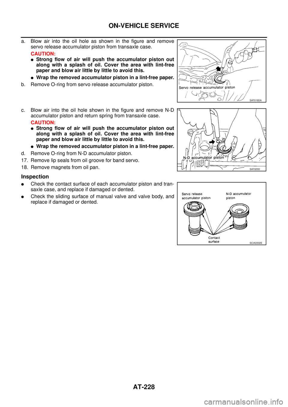
a. Blow air into the oil hole as shown in the figure and remove
servo release accumulator piston from transaxle case.
CAUTION:
�Strong flow of air will push the accumulator piston out
along with a splash of oil. Cover the area with lint-free
paper and blow air little by little to avoid this.
�Wrap the removed accumulator piston in a lint-free paper.
b. Remove O-ring from servo release accumulator piston.
c. Blow air into the oil hole shown in the figure and remove N-D
accumulator piston and return spring from transaxle case.
CAUTION:
�Strong flow of air will push the accumulator piston out
along with a splash of oil. Cover the area with lint-free
paper and blow air little by little to avoid this.
�Wrap the removed accumulator piston in a lint-free paper.
d. Remove O-ring from N-D accumulator piston.
17. Remove lip seals from oil groove for band servo.
18. Remove magnets from oil pan.
Inspection
�Check the contact surface of each accumulator piston and tran-
saxle case, and replace if damaged or dented.
�Check the sliding surface of manual valve and valve body, and
replace if damaged or dented.
SAT019DA
SAT020D
SCIA3302E
Page 237 of 3502

ON-VEHICLE SERVICE
AT-229
D
E
F
G
H
I
J
K
L
MA
B
AT
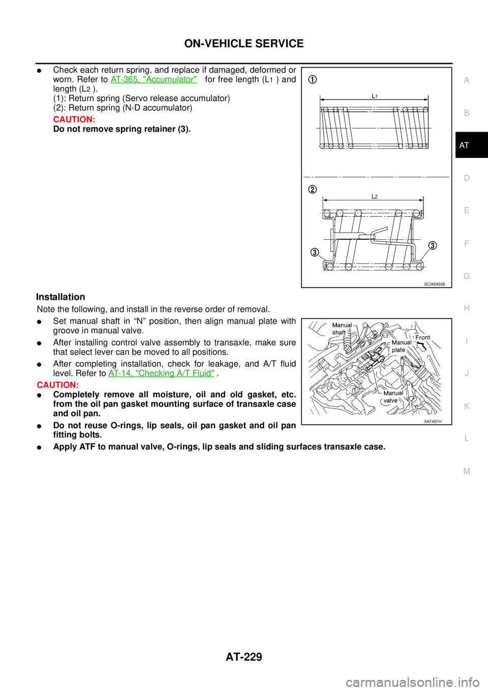
�Check each return spring, and replace if damaged, deformed or
worn. Refer to AT- 3 6 5 , "
Accumulator" for free length (L1 ) and
length (L
2 ).
(1): Return spring (Servo release accumulator)
(2): Return spring (N-D accumulator)
CAUTION:
Do not remove spring retainer (3).
Installation
Note the following, and install in the reverse order of removal.
�Set manual shaft in “N” position, then align manual plate with
groove in manual valve.
�After installing control valve assembly to transaxle, make sure
that select lever can be moved to all positions.
�After completing installation, check for leakage, and A/T fluid
level. Refer to AT- 1 4 , "
Checking A/T Fluid" .
CAUTION:
�Completely remove all moisture, oil and old gasket, etc.
from the oil pan gasket mounting surface of transaxle case
and oil pan.
�Do not reuse O-rings, lip seals, oil pan gasket and oil pan
fitting bolts.
�Apply ATF to manual valve, O-rings, lip seals and sliding surfaces transaxle case.
SCIA6955E
SAT497H
Page 238 of 3502
AT-230
ON-VEHICLE SERVICE
Park/Neutral Position (PNP) SwitchBCS00155
COMPONENTS
REMOVAL AND INSTALLATION
Removal
1. Set selector lever in “N” position.
2. Remove front tire LH from vehicle.
3. Remove LH splash guard. (Front fender side)
4. Remove engine under cover.
5. Remove control cable from manual shaft.
6. Remove PNP switch fixing bolts.
7. Remove PNP switch from transaxle assembly.
Installation
Note the following, and install in the reverse order of removal.
�Align PNP switch position when installing.
�After installation is completed, adjust and check A/T position. Refer to AT- 2 1 5 , "Adjustment of A/T Posi-
tion" , AT- 2 1 5 , "Checking of A/T Position" .
1. A/T 2. PNP switch
Refer to GI section to make sure icons (symbol marks) in the figure. Refer to GI-10, "
Components" .
SCIA7833E
SCIA2783E
SCIA3156E
Page 239 of 3502

ON-VEHICLE SERVICE
AT-231
D
E
F
G
H
I
J
K
L
MA
B
AT
�After installation is completed, check continuity of PNP switch. Refer to AT- 1 6 1 , "PNP, 3RD POSITION
SWITCH AND CLOSED THROTTLE, WIDE OPEN THROTTLE POSITION SIGNAL" .
PARK/NEUTRAL POSITION (PNP) SWITCH ADJUSTMENT
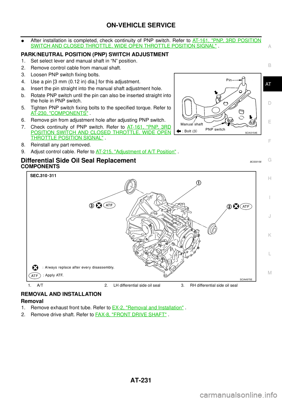
1. Set select lever and manual shaft in “N” position.
2. Remove control cable from manual shaft.
3. Loosen PNP switch fixing bolts.
4. Use a pin [3 mm (0.12 in) dia.] for this adjustment.
a. Insert the pin straight into the manual shaft adjustment hole.
b. Rotate PNP switch until the pin can also be inserted straight into
the hole in PNP switch.
5. Tighten PNP switch fixing bolts to the specified torque. Refer to
AT- 2 3 0 , "
COMPONENTS" .
6. Remove pin from adjustment hole after adjusting PNP switch.
7. Check continuity of PNP switch. Refer to AT- 1 6 1 , "
PNP, 3RD
POSITION SWITCH AND CLOSED THROTTLE, WIDE OPEN
THROTTLE POSITION SIGNAL" .
8. Reinstall any part removed.
9. Adjust control cable. Refer to AT- 2 1 5 , "
Adjustment of A/T Position" .
Differential Side Oil Seal ReplacementBCS00156
COMPONENTS
REMOVAL AND INSTALLATION
Removal
1. Remove exhaust front tube. Refer to EX-2, "Removal and Installation" .
2. Remove drive shaft. Refer to FA X - 8 , "
FRONT DRIVE SHAFT" .
SCIA3154E
1. A/T 2. LH differential side oil seal 3. RH differential side oil seal
SCIA4970E
Page 240 of 3502
AT-232
ON-VEHICLE SERVICE
3. Remove differential side oil seals using a flat-bladed screw-
driver.
CAUTION:
Be careful not to scratch transaxle case and converter
housing.
Installation
1. Drive differential side oil seals using the drift below into case
until it become flush. Refer to dimensions “A” and “B”.
Unit: mm (in)
NOTE:
Differential side oil seal pulling direction is used as the refer-
ence.
Drift to be used:
CAUTION:
�Do not reuse differential side oil seals.
�Apply ATF to differential side oil seals.
2. Reinstall any part removed.
CAUTION:
If lubricant leak has occurred, after finishing work, check A/T fluid level. Refer to AT- 1 4 , "
Checking
A/T Fluid" .
SCIA4857E
Dimensions “A”, “B” 0± 0.5 (0±0.020)
SCIA4858E
Location Tool number
Transaxle case side (left) ST33400001
Converter housing side (right) ST33400001
SCIA4739E
Page 241 of 3502
ON-VEHICLE SERVICE
AT-233
D
E
F
G
H
I
J
K
L
MA
B
AT
Revolution Sensor ReplacementBCS00157
COMPONENTS
REMOVAL AND INSTALLATION
Removal
1. Remove front tire LH from vehicle.
2. Remove LH splash guard. (Front fender side)
3. Disconnect revolution sensor harness connector.
4. Remove revolution sensor from transaxle assembly.
5. Remove O-ring from revolution sensor.
Installation
Note the following, and install in the reverse order of removal.
1. A/T 2. Revolution sensor 3. O-ring
SCIA4864E
SCIA2783E
SCIA2788E
Page 242 of 3502
AT-234
ON-VEHICLE SERVICE
CAUTION:
�Do not reuse O-ring.
�Apply petroleum jelly to O-ring.
�Be careful not to mis-connect because shape of connectors
are same as turbine revolution sensor (power train revolu-
tion sensor).
NOTE:
For prevent mis-connection, revolution sensor harness connec-
tor is color taped for identification.
Turbine Revolution Sensor (Power Train Revolution Sensor) ReplacementBCS00158
COMPONENTS
SCIA5007E
1. A/T 2. Turbine revolution sensor (power
train revolution sensor)3. O-ring
SCIA4865E
Page 243 of 3502
ON-VEHICLE SERVICE
AT-235
D
E
F
G
H
I
J
K
L
MA
B
AT
REMOVAL AND INSTALLATION
Removal
1. Remove front tire LH from vehicle.
2. Remove LH splash guard. (Front fender side)
3. Disconnect turbine revolution sensor (power train revolution
sensor) harness connector.
4. Remove turbine revolution sensor (power train revolution sen-
sor) from transaxle assembly.
5. Remove O-ring from turbine revolution sensor (power train revo-
lution sensor).
Installation
Note the following, and install in the reverse order of removal.
CAUTION:
�Do not reuse O-ring.
�Apply petroleum jelly to O-ring.
�Be careful not to mis-connect because shape of connectors
are same as revolution sensor.
NOTE:
For prevent mis-connection, revolution sensor harness connec-
tor is color taped for identification.
SCIA2783E
SCIA2790E
SCIA5007E