Page 443 of 3502
TROUBLE DIAGNOSIS
ATC-65
C
D
E
F
G
H
I
K
L
MA
B
AT C
Mode Door Control Specification
COMPONENT DESCRIPTION
Mode Door Motor
The mode door motor is attached to the heater & cooling unit assem-
bly. It rotates so that air is discharged from the outlet set by the uni-
fied meter and A/C amp. Motor rotation is conveyed to a link which
activates the mode door.
DIAGNOSIS PROCEDURE FOR MODE DOOR MOTOR
SYMPTOM: Mode door motor does not operate normally.
Perform diagnosis procedure. Refer to AT C - 5 9 , "
DIAGNOSIS PROCEDURE FOR LAN CIRCUIT" .
RJIA1778E
RJIA3255E
Page 446 of 3502
ATC-68
TROUBLE DIAGNOSIS
COMPONENT DESCRIPTION
Air Mix Door Motor
The air mix door motors are attached to the heater & cooling unit
assembly. It rotates so that the air mix door is opened or closed to a
position set by the unified meter and A/C amp. Air mix door rotates
gear of slide door directly and moves slide door.
DIAGNOSIS PROCEDURE FOR AIR MIX DOOR MOTOR
SYMPTOM: Discharge air temperature does not change.
Perform diagnosis procedure. Refer to AT C - 5 9 , "
DIAGNOSIS PROCEDURE FOR LAN CIRCUIT" .
Air Mix Door Motor PBR CircuitBJS000G3
SYMPTOM
�Discharge air temperature does not change.
�PBR circuit is open or shorted.
DIAGNOSIS PROCEDURE FOR AIR MIX DOOR MOTOR PBR
Perform diagnosis procedure. Refer to AT C - 5 9 , "DIAGNOSIS PROCEDURE FOR LAN CIRCUIT" .
RJIA3257E
RJIA3258E
Page 462 of 3502
ATC-84
TROUBLE DIAGNOSIS
Insufficient CoolingBJS000G7
SYMPTOM: Insufficient cooling
INSPECTION FLOW
*1AT C - 4 7 , "FUNCTION CONFIRMA-
TION PROCEDURE", see No. 2 to 6.*2ATC-66, "
Air Mix Door Motor Circuit"*3ATC-87, "Test Reading"
*4AT C - 5 2 , "AUXILIARY MECHANISM:
TEMPERATURE SETTING TRIM-
MER"
*5ATC-47, "FUNCTION CONFIRMA-
TION PROCEDURE", see No. 13.*6ATC-59, "
LAN System Circuit"
*7AT C - 7 2 , "Blower Motor Circuit"*8ATC-78, "Magnet Clutch Circuit"*9ATC-85, "PERFORMANCE TEST
DIAGNOSIS"
*10AT C - 5 4 , "Operational Check"*11EM-14, "Checking Drive Belts" (QR
engine) or EM-128, "
Checking Drive
Belts" (VQ engine)*12EC-218, "
System Description" (QR
engine) or EC-575, "
System
Description" (VQ engine)
SJIA1652E
Page 466 of 3502

ATC-88
TROUBLE DIAGNOSIS
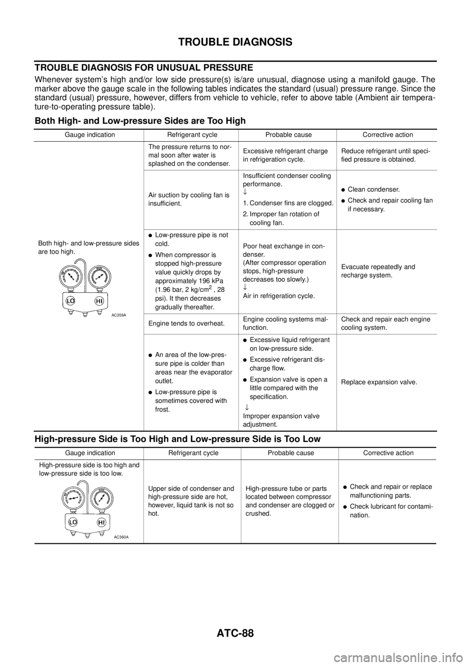
TROUBLE DIAGNOSIS FOR UNUSUAL PRESSURE
Whenever system’s high and/or low side pressure(s) is/are unusual, diagnose using a manifold gauge. The
marker above the gauge scale in the following tables indicates the standard (usual) pressure range. Since the
standard (usual) pressure, however, differs from vehicle to vehicle, refer to above table (Ambient air tempera-
ture-to-operating pressure table).
Both High- and Low-pressure Sides are Too High
High-pressure Side is Too High and Low-pressure Side is Too Low
Gauge indication Refrigerant cycle Probable cause Corrective action
Both high- and low-pressure sides
are too high.The pressure returns to nor-
mal soon after water is
splashed on the condenser.Excessive refrigerant charge
in refrigeration cycle.Reduce refrigerant until speci-
fied pressure is obtained.
Air suction by cooling fan is
insufficient.Insufficient condenser cooling
performance.
↓
1. Condenser fins are clogged.
2. Improper fan rotation of
cooling fan.
�Clean condenser.
�Check and repair cooling fan
if necessary.
�Low-pressure pipe is not
cold.
�When compressor is
stopped high-pressure
value quickly drops by
approximately 196 kPa
(1.96 bar, 2 kg/cm
2 , 28
psi). It then decreases
gradually thereafter.Poor heat exchange in con-
denser.
(After compressor operation
stops, high-pressure
decreases too slowly.)
↓
Air in refrigeration cycle.Evacuate repeatedly and
recharge system.
Engine tends to overheat.Engine cooling systems mal-
function.Check and repair each engine
cooling system.
�An area of the low-pres-
sure pipe is colder than
areas near the evaporator
outlet.
�Low-pressure pipe is
sometimes covered with
frost.
�Excessive liquid refrigerant
on low-pressure side.
�Excessive refrigerant dis-
charge flow.
�Expansion valve is open a
little compared with the
specification.
↓
Improper expansion valve
adjustment.Replace expansion valve.
AC359A
Gauge indication Refrigerant cycle Probable cause Corrective action
High-pressure side is too high and
low-pressure side is too low.
Upper side of condenser and
high-pressure side are hot,
however, liquid tank is not so
hot.High-pressure tube or parts
located between compressor
and condenser are clogged or
crushed.
�Check and repair or replace
malfunctioning parts.
�Check lubricant for contami-
nation.
AC360A
Page 468 of 3502

ATC-90
TROUBLE DIAGNOSIS
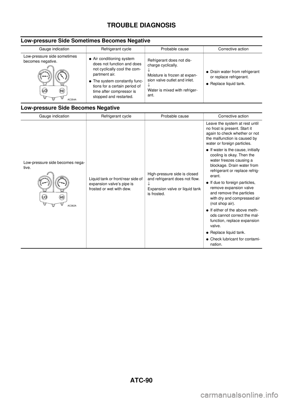
Low-pressure Side Sometimes Becomes Negative
Low-pressure Side Becomes Negative
Gauge indication Refrigerant cycle Probable cause Corrective action
Low-pressure side sometimes
becomes negative.
�Air conditioning system
does not function and does
not cyclically cool the com-
partment air.
�The system constantly func-
tions for a certain period of
time after compressor is
stopped and restarted.Refrigerant does not dis-
charge cyclically.
↓
Moisture is frozen at expan-
sion valve outlet and inlet.
↓
Water is mixed with refriger-
ant.
�Drain water from refrigerant
or replace refrigerant.
�Replace liquid tank.
AC354A
Gauge indication Refrigerant cycle Probable cause Corrective action
Low-pressure side becomes nega-
tive.
Liquid tank or front/rear side of
expansion valve’s pipe is
frosted or wet with dew.High-pressure side is closed
and refrigerant does not flow.
↓
Expansion valve or liquid tank
is frosted.Leave the system at rest until
no frost is present. Start it
again to check whether or not
the malfunction is caused by
water or foreign particles.
�If water is the cause, initially
cooling is okay. Then the
water freezes causing a
blockage. Drain water from
refrigerant or replace refrig-
erant.
�If due to foreign particles,
remove expansion valve
and remove the particles
with dry and compressed air
(not shop air).
�If either of the above meth-
ods cannot correct the mal-
function, replace expansion
valve.
�Replace liquid tank.
�Check lubricant for contami-
nation.
AC362A
Page 477 of 3502
TROUBLE DIAGNOSIS
ATC-99
C
D
E
F
G
H
I
K
L
MA
B
AT C
In-vehicle Sensor CircuitBJS000GD
COMPONENT DESCRIPTION
In-vehicle Sensor
The in-vehicle sensor is located on instrument driver lower panel. It
converts variations in temperature of compartment air drawn from
the aspirator into a resistance value. It is then input into the unified
meter and A/C amp.
Aspirator
The aspirator is located on driver’s side of heater & cooling unit
assembly. It produces vacuum pressure due to air discharged from
the heater & cooling unit assembly, continuously taking compartment
air in the aspirator.
RJIA3276E
RJIA3277E
RJIA1804E
Page 483 of 3502

TROUBLE DIAGNOSIS
ATC-105
C
D
E
F
G
H
I
K
L
MA
B
AT C
Intake Sensor CircuitBJS000GF
COMPONENT DESCRIPTION
Intake Sensor
The intake sensor is located on the heater & cooling unit assembly. It
converts temperature of air after it passes through the evaporator
into a resistance value which is then input to the unified meter and A/
C amp.
DIAGNOSIS PROCEDURE FOR INTAKE SENSOR
SYMPTOM: Intake sensor circuit is open or shorted. (24 or −24 is
indicated on unified meter and A/C amp. as a result of performing
self-diagnosis STEP-2.)
1. CHECK VOLTAGE BETWEEN INTAKE SENSOR AND GROUND
1. Disconnect intake sensor connector.
2. Turn ignition switch ON.
3. Check voltage between intake sensor harness connector M256
terminal 1 and ground.
OK or NG
OK >> GO TO 2.
NG >> GO TO 4.
2. CHECK CIRCUIT CONTINUITY BETWEEN INTAKE SENSOR AND UNIFIED METER AND A/C AMP.
1. Turn ignition switch OFF.
2. Disconnect unified meter and A/C amp. connector.
3. Check continuity between intake sensor harness connector
M256 terminal 2 and unified meter and A/C amp. harness con-
nector M45 terminal 49.
OK or NG
OK >> GO TO 3.
NG >> Repair harness or connector.
RJIA3281E
RJIA1458E
1 – Ground : Approx. 5 V
RJIA1809E
2 – 49 : Continuity should exist.
RJIA1810E
Page 492 of 3502
ATC-114
BLOWER UNIT
Disassembly and AssemblyBJS000HC
CAUTION:
If retaining tabs are damaged while disassembling blower unit,
use 7 screws (27111-2Y000) to assemble blower unit.
1. Intake adapter 2. Plate clip 3. Nut
4. Blower fan 5. Washer 6. Fan control amp.
7. Screw 8. Motor cover 9. Cooling hose
10. Intake lower case 11. Intake door 1 12. Intake door lever 1
13. Intake door link 14. Intake door lever 2 15. Intake door motor
16. Air conditioner filter 17. Filter cover 18. Intake door 2
19. Intake box 20. Intake upper case 21. Blower motor
RJIA3294E
RJIA3295E