Page 1098 of 3502

CVT-92
DTC P0740 TORQUE CONVERTER CLUTCH SOLENOID VALVE
3. CHECK HARNESS BETWEEN TCM AND TORQUE CONVERTER CLUTCH SOLENOID VALVE
1. Turn ignition switch OFF.
2. Disconnect TCM connector and CVT unit harness connector.
3. Check continuity between TCM connector terminal and CVT unit
harness connector terminal.
4. If OK, check harness for short to ground and short to power.
5. If OK, check continuity between ground and CVT assembly.
6. Reinstall any part removed.
OK or NG
OK >> GO TO 4.
NG >> Repair or replace damaged parts.
4. CHECK VALVE RESISTANCE
1. Turn ignition switch OFF.
2. Disconnect CVT unit harness connector.
3. Check resistance between CVT unit harness connector terminal
and ground.
OK or NG
OK >> GO TO 5.
NG >> Repair or replace damaged parts.
5. CHECK DTC
Perform “DTC Confirmation Procedure”. Refer to CVT-89, "
DTC Confirmation Procedure" .
OK or NG
OK >>INSPECTION END
NG >> GO TO 6.
6. CHECK TCM
1. Check TCM input/output signal. Refer to CVT-40, "
TCM Input/Output Signal Reference Values" .
2. If NG, re-check TCM pin terminals for damage or loose connection with harness connector.
OK or NG
OK >>INSPECTION END
NG >> Repair or replace damaged parts.
Item Connector Terminal Continuity
TCM F106 3
Ye s
CVT unit harness connector F49 12
SCIA4683E
Solenoid Valve Connector Terminal Resistance
(Approx.)
Torque converter clutch
solenoid valveF49 12 - Ground 3 - 9 Ω
SCIA4684E
Page 1099 of 3502
DTC P0740 TORQUE CONVERTER CLUTCH SOLENOID VALVE
CVT-93
D
E
F
G
H
I
J
K
L
MA
B
CVT
Component InspectionBCS001IO
TORQUE CONVERTER CLUTCH SOLENOID VALVE
1. Turn ignition switch OFF.
2. Disconnect CVT unit harness connector.
3. Check resistance between CVT unit harness connector terminal
and ground.
4. If NG, replace the transaxle assembly. Refer to CVT-193,
"Removal and Installation" .
Solenoid Valve Connector TerminalResistance
(Approx.)
Torque converter clutch
solenoid valveF49 12 - Ground 3 - 9 Ω
SCIA4684E
Page 1100 of 3502

DTC P0744 A/T TCC S/V FUNCTION (LOCK-UP)PFP:31940
DescriptionBCS001IP
This malfunction is detected when the torque converter clutch does not lock-up a")
CVT-94
DTC P0744 A/T TCC S/V FUNCTION (LOCK-UP)
DTC P0744 A/T TCC S/V FUNCTION (LOCK-UP)PFP:31940
DescriptionBCS001IP
This malfunction is detected when the torque converter clutch does not lock-up as instructed by the TCM. This
is not only caused by electrical malfunction (circuits open or shorted), but also by mechanical malfunction such
as control valve sticking, improper solenoid valve operation, etc.
CONSULT-II Reference ValueBCS001IQ
Remarks: Specification data are reference values.
On Board Diagnosis LogicBCS001IR
Diagnostic trouble code “P0744 A/T TCC S/V FNCTN” with CONSULT-II is detected under the following condi-
tions.
�When CVT cannot perform lock-up even if electrical circuit is good.
�When TCM compares difference value with slip revolution and detects an irregularity.
Possible CauseBCS001IS
�Torque converter clutch solenoid valve
�Hydraulic control circuit
DTC Confirmation ProcedureBCS001IT
CAUTION:
Always drive vehicle at a safe speed.
NOTE:
If “DTC Confirmation Procedure” has been previously performed, always turn ignition switch OFF and
wait at least 10 seconds before performing the next test.
After the repair, touch “ERASE” on “SELF-DIAG RESULTS” and then perform the following procedure to con-
firm the malfunction is eliminated.
WITH CONSULT-II
1. Turn ignition switch ON. (Do not start engine.)
2. Select “DATA MONITOR” mode for “TRANSMISSION” with
CONSULT-II.
3. Start engine and maintain the following condition for at least 30
seconds.
ACC PEDAL OPEN: More than 1.0/8
RANGE: “D” position
[Vehicle speed: Constant speed of more than 40 km/h (25
MPH)]
4. If DTC is detected go to CVT-95, "
Diagnostic Procedure" .
Item name Condition Display value
ENG SPEED SIG Engine running Closely matches the tachometer reading
PRI SPEED SEN During driving (lock-up ON) Approximately matches the engine speed
BCIA0031E
Page 1101 of 3502

CVT-95
D
E
F
G
H
I
J
K
L
MA
B
CVT
Diagnostic ProcedureBCS001IU
1. CHECK INPUT SIGNALS
With CONSULT-II
1. Start engine.
2. Select “ECU INPUT SIGNALS” in")
DTC P0744 A/T TCC S/V FUNCTION (LOCK-UP)
CVT-95
D
E
F
G
H
I
J
K
L
MA
B
CVT
Diagnostic ProcedureBCS001IU
1. CHECK INPUT SIGNALS
With CONSULT-II
1. Start engine.
2. Select “ECU INPUT SIGNALS” in “DATA MONITOR” mode for
“TRANSMISSION” with CONSULT-II.
3. Start vehicle.
4. Check if there is a great difference between “ENG SPEED SIG”
and “PRI SPEED SEN”. (Lock-up ON.)
OK or NG
OK >> GO TO 5.
NG >> GO TO 2.
2. CHECK LINE PRESSURE
Perform line pressure test. Refer to CVT-33, "
LINE PRESSURE
TEST" .
OK or NG
OK >> GO TO 3.
NG >> Repair or replace damaged parts. Refer to CVT-34,
"Judgement of Line Pressure Test" .
3. DETECT MALFUNCTIONING ITEM
Check the following:
�Torque converter clutch solenoid valve. Refer to CVT-93, "Component Inspection" .
�Lock-up select solenoid valve. Refer to CVT-151, "Component Inspection" .
OK or NG
OK >> GO TO 4.
NG >> Repair or replace damaged parts.
4. CHECK SECONDARY SPEED SENSOR SYSTEM AND PRIMARY SPEED SENSOR SYSTEM
Check output speed sensor (secondary speed sensor) system and input speed sensor (primary speed sensor)
system. Refer to CVT-79, "
DTC P0720 VEHICLE SPEED SENSOR CVT (SECONDARY SPEED SENSOR)" ,
CVT-74, "
DTC P0715 INPUT SPEED SENSOR CIRCUIT (PRI SPEED SENSOR)" .
OK or NG
OK >> GO TO 5.
NG >> Repair or replace damaged parts.
Item name Condition Display value
ENG SPEED SIG Engine runningClosely matches the
tachometer reading
PRI SPEED SEN During driving (lock-up ON)Approximately matches
the engine speed
SCIA2279E
SAT494G
Page 1199 of 3502
TRANSAXLE ASSEMBLY
CVT-193
D
E
F
G
H
I
J
K
L
MA
B
CVT
TRANSAXLE ASSEMBLYPFP:32020
Removal and InstallationBCS001N0
COMPONENTS
1. Air breather hose 2. Rear gusset 3. CVT fluid level gauge
4. CVT fluid charging pipe 5. O-ring 6. Fluid cooler tube
7. Copper washer 8. Hose clamp 9. CVT fluid cooler hose
10. CVT fluid cooler hose 11. LH engine mounting bracket 12. LH engine mounting insulator
13. Transaxle assembly
Refer to GI section to make sure icons (symbol marks) in the figure. Refer to GI-10, "
Components" .
However, refer to the following symbols for others.
: For tightening torque, refer to CVT-196, "
INSTALLATION" .
(A) : To radiator
SCIA7899E
Page 1200 of 3502

CVT-194
TRANSAXLE ASSEMBLY
REMOVAL
CAUTION:
The transaxle assembly itself cannot be removed from the vehicle. Remove the transaxle assembly
and engine assembly together from the vehicle.
1. Disconnect the batter cable from the negative terminal.
2. Remove engine undercover.
3. Remove exhaust front tube with power tool. Refer to EX-2, "
Removal and Installation" .
4. Remove rear plate cover. Refer to EM-145, "
Removal and
Installation" .
5. Turn crankshaft, and remove the four tightening nuts for drive
plate and torque converter.
CAUTION:
The crankshaft should be rotated clockwise, viewed from
the front of the engine.
6. Remove the four bolts in the figure.
7. Remove transaxle assembly and engine assembly together
from the vehicle. Refer to EM-223, "
Removal and Installation" .
8. Remove drive shaft. Refer to FA X - 11 , "
Removal and Installation
(LH)" .
CAUTION:
Be sure to replace the differential side oil seal with new one
at the every removal of drive shaft. Refer to CVT-187,
"Removal and Installation" .
9. Remove rear gusset.
10. Remove CVT fluid level gauge.
11. Remove CVT fluid charging pipe.
12. Remove O-ring from CVT fluid charging pipe.
13. Disconnect harness connector and wire harness.
SCIA6475E
SCIA1861E
SCIA1893E
SCIA1894E
Page 1201 of 3502
 (1) from engine
assembly. Refer to EM-145, \"
Removal and Installation\" .
CAUTION:
�Do not subject it")
TRANSAXLE ASSEMBLY
CVT-195
D
E
F
G
H
I
J
K
L
MA
B
CVT
14. Remove crankshaft position sensor (POS) (1) from engine
assembly. Refer to EM-145, "
Removal and Installation" .
CAUTION:
�Do not subject it to impact by dropping or hitting it.
�Do not disassemble.
�Do not allow metal filings, etc., to get on the sensor's
front edge magnetic area.
�Do not place in an area affected by magnetism.
15. Remove starter motor. Refer to SC-18, "
Removal and Installa-
tion" .
16. Remove CVT fluid cooler valve assembly (1). (With CVT fluid
cooler tube assembly and heater hose). Refer to CVT-189, "
CVT
Fluid Cooler Removal and Installation" .
(A): Bolt (4)
(B): Hose clamp (3)
17. Install slinger to transaxle assembly.
18. Remove LH engine mounting bracket and LH engine mounting
insulator.
19. Remove transaxle assembly fixing bolts with power tool.
20. Remove transaxle assembly from engine assembly with a hoist.
CAUTION:
Secure torque converter to prevent it from dropping.
21. Remove air breather hose. Refer to CVT-186, "
Removal and
Installation" .
22. Remove CVT fluid cooler hoses.
23. Remove fluid cooler tube.
SCIA6759E
SCIA6880E
SCIA4355E
SCIA1868E
Page 1202 of 3502
CVT-196
TRANSAXLE ASSEMBLY
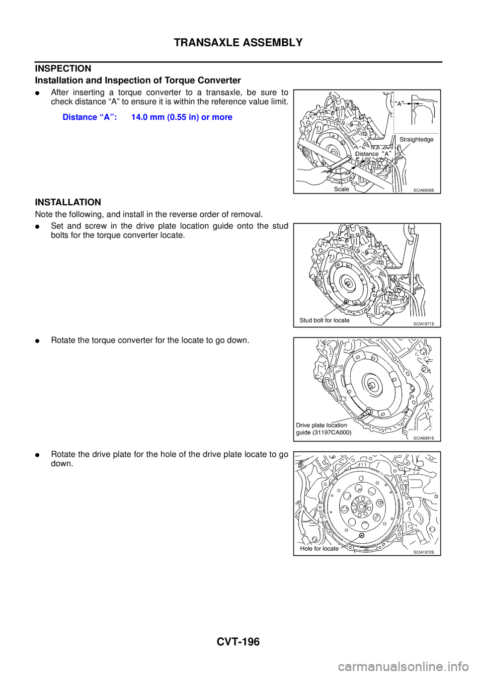
INSPECTION
Installation and Inspection of Torque Converter
�After inserting a torque converter to a transaxle, be sure to
check distance “A” to ensure it is within the reference value limit.
INSTALLATION
Note the following, and install in the reverse order of removal.
�Set and screw in the drive plate location guide onto the stud
bolts for the torque converter locate.
�Rotate the torque converter for the locate to go down.
�Rotate the drive plate for the hole of the drive plate locate to go
down.Distance “A”: 14.0 mm (0.55 in) or more
SCIA6858E
SCIA1871E
SCIA6881E
SCIA1872E